Week 8 - Challenge 1 - Base Bracket Design
AIM:
- To make the model from the provided input class-A surface.
INTRODUCTION:
- To create the model using the reference of Class-A surface.
- The class -B surfaces are created by the extraction of class-A surfaces.
- The class-C surfaces are created by extracting the outer boundary of the class-A surface and applying the swept feature.
METHODOLOGY:
- In this model we have to consider the following things:
1. Tooling axis
2. Draft analysis
3. Class-A surface
4. Class- B surface
5. Class-C surface
6. Making a solid model from the surface.
TOOLING AXIS:
- Tooling axis is the defined axis to perform the manufacturing process within the injection molding according to its direction.
CREATION OF TOOLING AXIS:
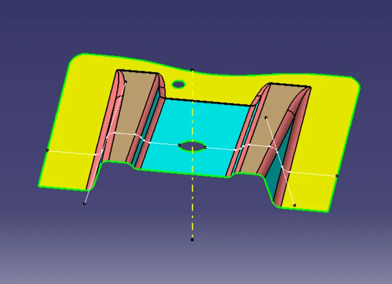
- Analysing the class-A surface by manual visualizing to see which direction is most suitable.
- According to the 3D view, the direction of the tooling axis to be chosen is perpendicular to the flat surface and holes.
- Create a point at the center of the hole.
- Create a line using the point-direction option and select the reference of z-direction for the line and name it as a dummy tooling axis.
- Create a parallel plane to the dummy tooling axis with reference to the yz plane, then intersect the plane with the Class-A surface.
- From the intersection profile create two lines that are parallel to the dummy tooling axis and make the bisecting line using the reference of two lines with a center point.
- A formed bisecting line is called as main tooling axis.
DRAFT ANALYSIS:
- The analyzing of the model should maintain the nominal 3-degree draft angle to the tooling axis.
- Draft should be given to the plastic component to reduce the wear and tear and improve the production quality and accuracy while ejecting the part from the mold cavity.
How to perform the draft analysis
1. Go to insert < analysis< feature draft analysis.
2. Align the tooling axis with a compass.
3. Click on the surface to see whether it is in permissible limit draft values or not.
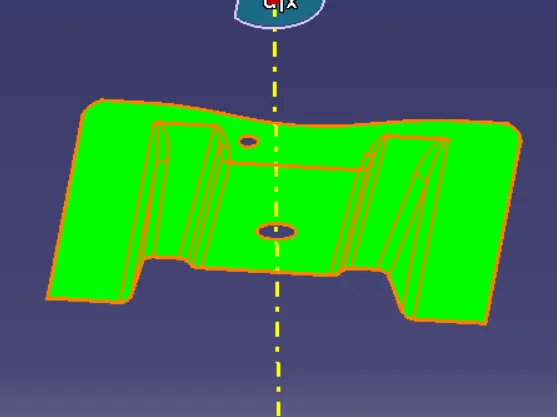
4. The entire surface should be green in colour.
DRAFT ANALYSIS FOR CLASS-A SURFACE:
DRAFT ANALYSIS FOR MODEL: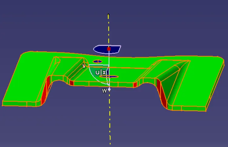
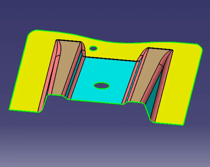
CLASS- A SURFACE:
- Class-A surface is given as an input surface by designers.
- Generally the class-A surfaces have the tangent continuity
- Class-A surface is the outermost aesthetic surface.
CLASS-B SURFACE:
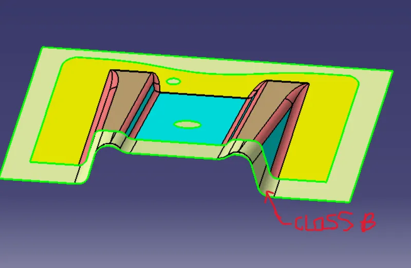
- The extraction of the Class-A surface is the class-B surface.
- Untrimmed the extracted surfaces from class A.
- The untrimmed surfaces are offset to the required thickness.
- After offsetting, all the surfaces are trimmed into the required shape.
- Give the fillets on the edges, especially given fillet radius values should maintain the uniform wall thickness.
- The class B fillet radius value=outer radius value(3mm) + thickness(2.5mm)
CLASS C SURFACE:
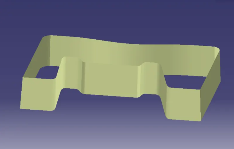
- Class C surface is the closing surface of class A and class B surfaces.
- It is the extraction of the boundary of class A surface.
- Apply the sweep feature to create the class c surface, For guide reference click the extracted boundary and for the drafting reference option click the tooling axis and give a 3-degree draft angle.
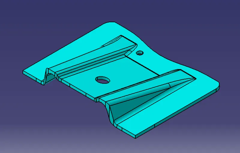
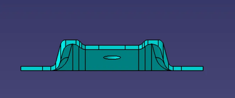
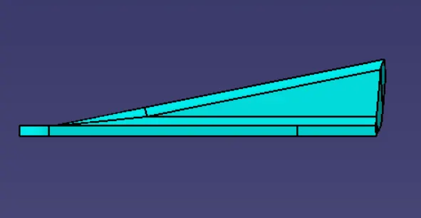
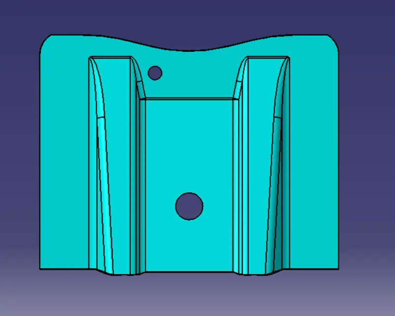
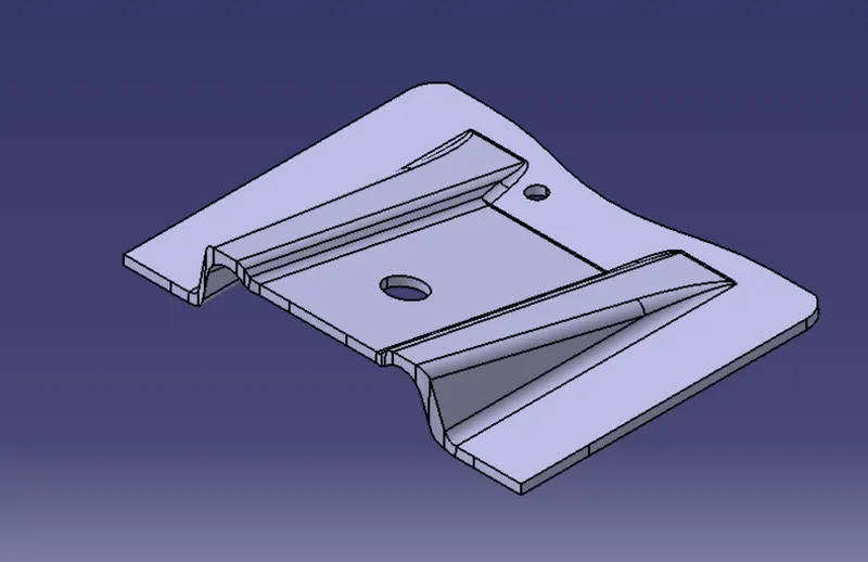
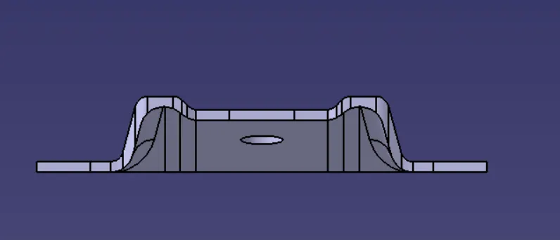
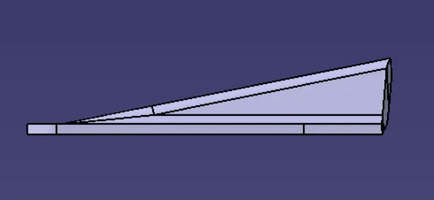
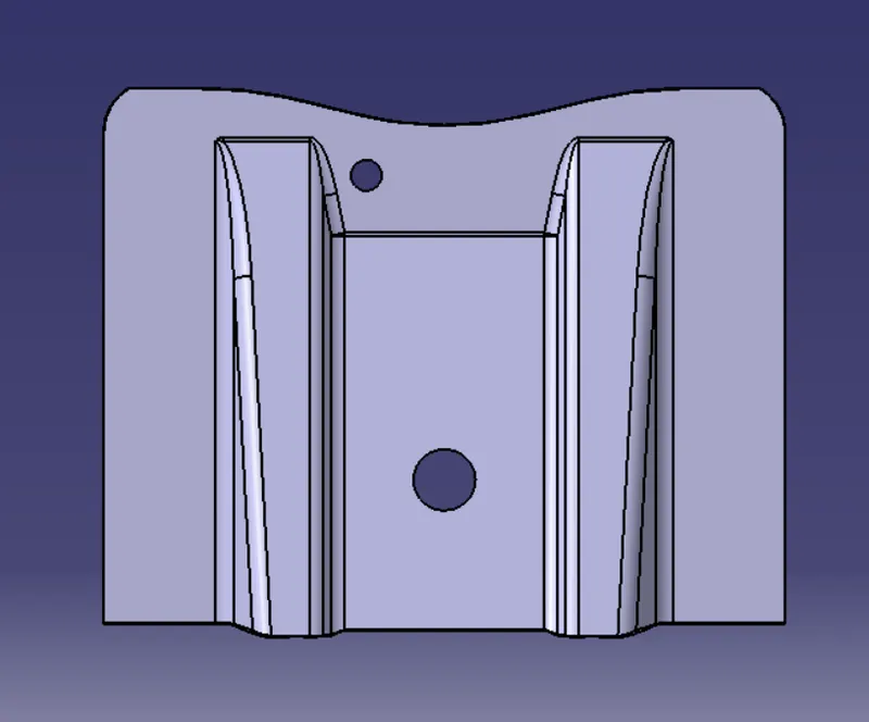
Final component images:
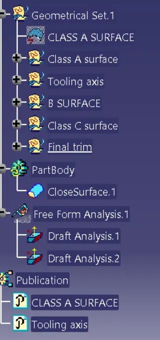
TREE STRUCTURE: