Week 8 - Challenge 1 - Base Bracket Design
Steps involved in crecating the Base Bracket Plastic component through the given Class-A surface:
STEP 1: Checking the given class A surface
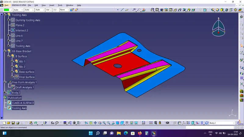
Checking wether in the given class A surface is properly joined or not.
Class A surface uare the Aesthetic surface which shows on the outside to the end user.
- We can have a visual check in CATA software.
- Or, we can use Boundary command to extract the boundary of the given Class A surface. The extracted wireframe will show us the open edges. if there are any unncessary gaps then they will show up as boundary indicating that the Class A surface given i s deffective.
- Or, we can use the join command. If the given surface is perfect then the join command will fail, indicating that the given Class A sirface is proper.
STEP 2: create the Tooling Axis.
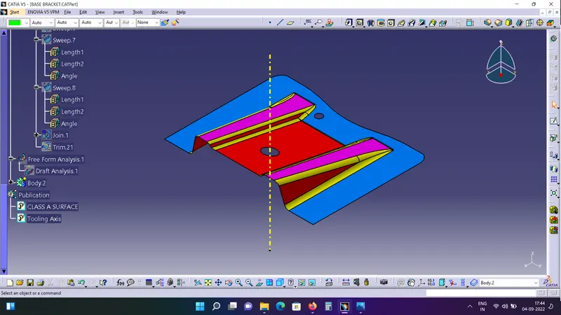
In this Step we can analyze which diRection we need to put the tooling axis and planes that may create complications and finally create the Tooling Axis.
- General consideration on selecting the parting side and tooling axis direction.
1. Any holes must be cleared in the main Tooling Axis. i.e., Tooling Axis will be perpendicular to the hole 2. Tooling axis ust be preffered to be perpendicular to any big flat faces of the part. 3. Dummy tooling axis must be created fiest by bisecting the lines of the elevated surfaces, then the final tooling axis must be created bisecting the dummy tooling axeses. This will clear all the faces. - Steps in creating Tooling Axis:
1. Create a point in the center of the hole. Create a line using "Point & Direction". Select the centre point of circle and Z component. This will be a Dummy Tooling Axis.
2. Create a plane perpendicualr to "YZ Plane" and at the center point. Use the "Intersect command" to intersect the Class A with the surface created. Output of this step will look like this.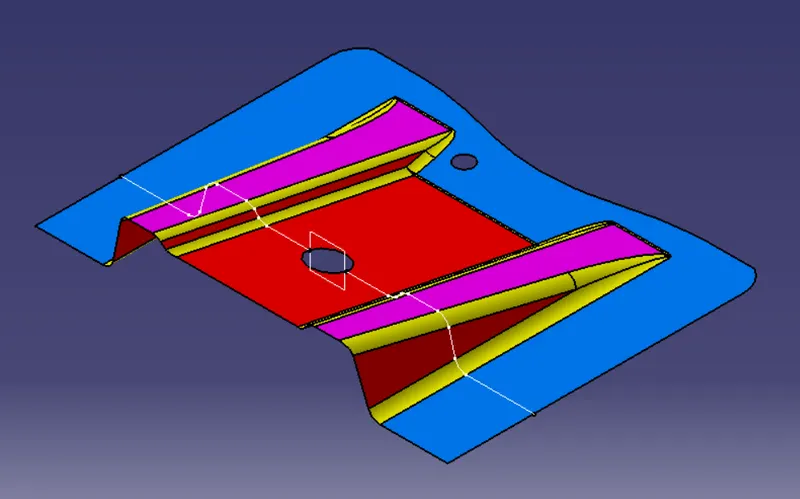
3. Create a sketch on the created plane and using "Point - Point" option. Create two lines of opposite surfaces.
4. Bisect the Two lines to get the Dummy Axis 1 of the tooling Axis.
5. Repeat same for other two slant faces to get Dummy Axis 2.
6. Bisect Both the Dummy Axeses to get the final Tooling AXis and rename the command to "Tooling Axis"
7. Publish both Class A surface and Tooling Axis as we will be requiring them Often. We can reach "Publication" command by typing "c: Publication" in the type box in the right bottom Conner.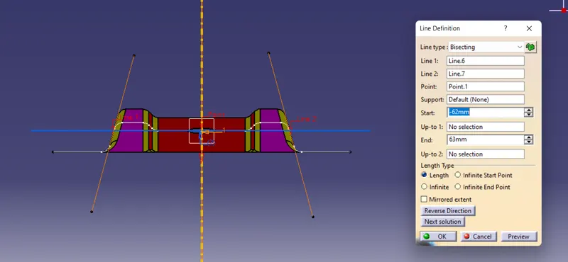
- Steps in Draft analysis.
In Automotive Plastic products generally anything around 3 degree is widely accepeted for Draft allowance. In special cases a Draft of 0.5 to 1 degree is also accepted.
1. "Insert" --> "Analysis" --> "Feature Draft Analysis"
2. A draft anlysis will be inserted.
3. Select the Component to perform draft analysis on and select the Tooling Axis.
4. In this example we check for a draft of 3 degrees so we have input 3 degree in the marked zone. Any face that clears 3 degree draft angle is shown in green. Our part shows green colour which means it clears the draft analysis. else the aprt would have represented red or blue colour.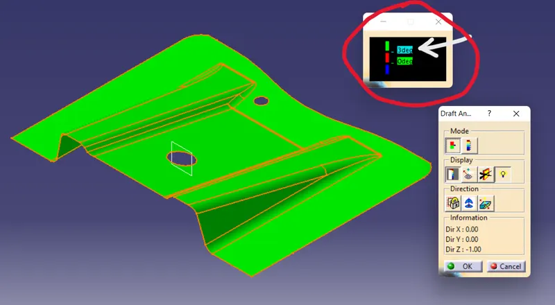
STEP 3: Create Class B surfaces. 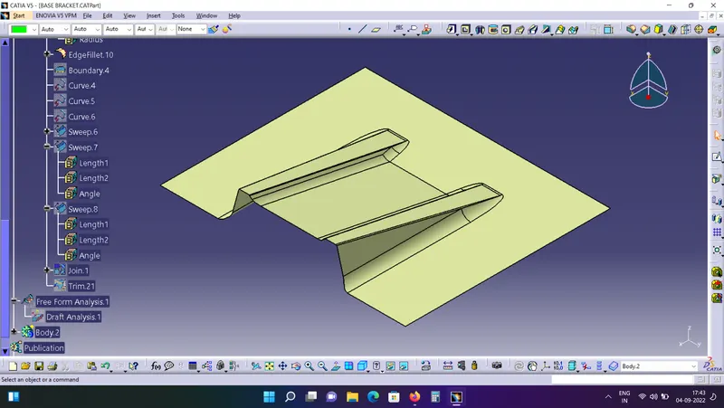
Create Class B surfaces.
Class B surfaces are aslo called engineering surfaces. It provides thickness and is an offset of Class A. All the enfineering Features are attached to Class B surface such as Screw Boss, Ribs, Dog House, etc.
- Class A surface with fillets will be difficult to offset or thicken, So first we convert or duplicate the given Class A surface.
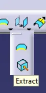
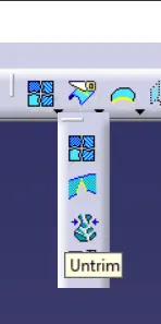
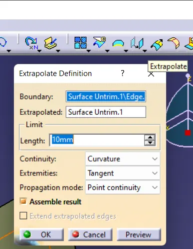
Extract the Flat surfaces. Untrim them to form a rectagular surface, and Extrapolate the surfaces to make sure they intersect with the adjascent surfaces. Repaeat steps for all the fat faces.- Offset the surfaces by 2.5mm to get the Class B suface.
- Trim off the extra surafes untill all the unnecessary faces are trimmed off.
- Provide fillets to the edges to get the final Class B surface.
STEP 4: CREATE CLASS C SURFACE.
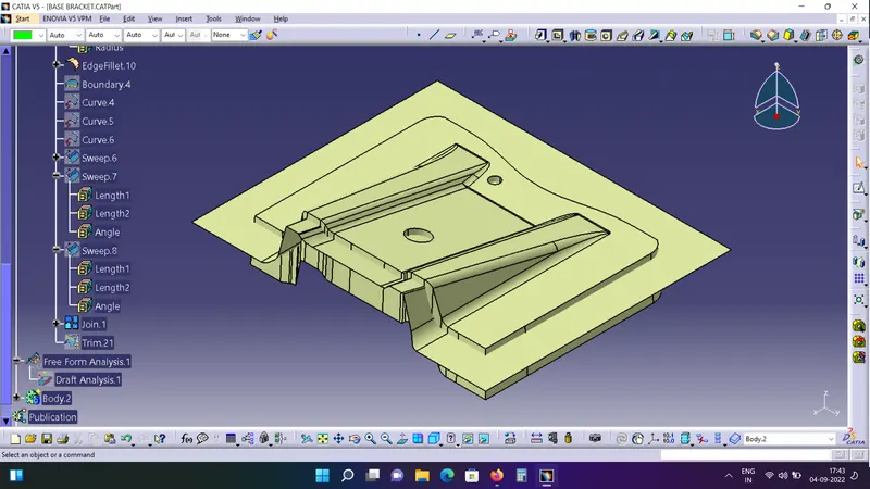
- Extract Boundary from the given Class A surface.
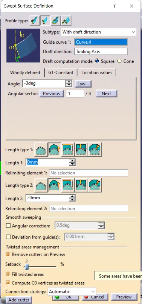
- Sweep the given boundary one by on. First the external surface and then the two internal Holes. Select boundary for Curve and Tooling Axis for direction. Take care of the inputs for draft angle as shown below.
STEP 5: TRIM TO GET THE FINAL SURFACE FOR THE PRODUCT.
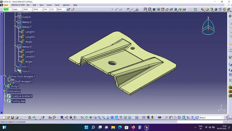
- Use the Join Command to first Join the Class A and Class C surface.
- Use the Joined SUrafce to make the final trim with the Class B surface.
- Make sure at the end the final surface is a joined surface.
- To do this use theBoundaey command. If the Boundaery command fails it means that the created surface is joined properly.
STEP 6: CLOSE SURFACE TO FORM SOLID:
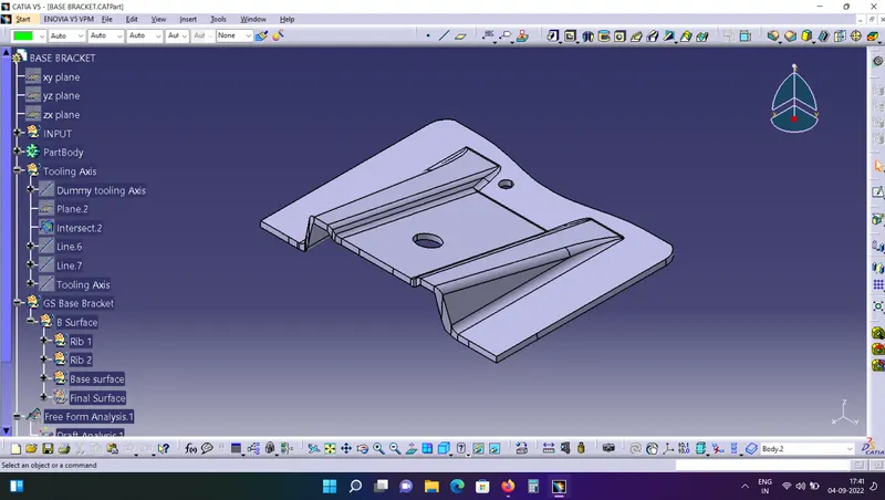
- Switch to Part design Work Bench.
- select the "Close surface command to create a solid Part.