Base Bracket Design
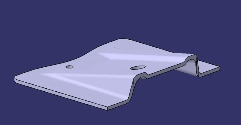
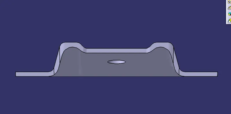
AIM: Create the Base Bracket Plastic component through the given Class-A surface.
INTRODUCTION:
CLASS-A SURFACE: a surface made by the designer which is given as an input to the plastic modeler to work on. It is aesthetic surface and the outer most surface.
CLASS-B SURFACE: a surface below a certain thickness from the class-A surface is class-B surface. This is the surface that contains engineering aspects of a model.
CLASS-C SURFACE: a surface that joins class-A and class-B surfaces is class-C surface.
THEORY:
Draft Analysis:
Draft analysis helps to detect if your drafted part is easily removable from the mold (in case of plastic component) or die (in case of sheet metal). All plastic components will have a minimum draft of 0.5 to 3deg. And for automotive sheet metal parts the draft will be 7deg or more. If a mold wall is perpendicular to the part ejection, there is ample friction or interference between the mold and the part which will not allow one to release from the other. This is why design engineers give a minimum draft to the part.
In CATIA V5 the feature draft analysis dialog box look like this:
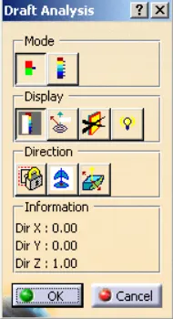
Mode:
- The mode option let you to choose between quick analysis and full analysis mode.
- In quick mode there are 3 ranges with blue, red and green colors. In case of plastic component we will set the draft angle as 3deg.
Display:
- The first box is to open and close the color scale dialogue box.
- The second box is the analysis under running point, when activating the checkbox and move the pointer over the surface. This option enables you to perform a local analysis. Arrows are displayed under the pointer, identifying the normal to the surface at the pointer location (green arrow), the draft direction (red arrow), and the tangent (blue arrow). As you move the pointer over the surface, the display is dynamically updated. Furthermore, circles are displayed indicating the plane tangent to the surface at this point. The displayed value indicates the angle between the draft direction and the tangent to the surface at the current point.
- Click the No Highlight Representations button to set the display option of highlight effect sources as "on/off". When checked "On" the surfaces are selected but they will not be seen in the specification tree.
- Click the Light Effect button and the colors of the analyzed elements react to the light source
Direction:
- The first check box is locked direction icon which is used to lock the direction of the compass after selecting the specified direction.
- Click on compass icon to specify the new pulling direction to remove the part.
- Click the Inverse button to automatically reverse the draft direction. When several elements are selected for analysis, the draft direction is inverted for each element when the button is clicked.
Tooling Axis:
- It is the direction in which the component will be ejecting after the molding process is completed.
- The direction of tooling axis should clear the maximum portion of the part.
- It should be selected in such way that number of side cores will be minimum as it will add more cost to the process.
Draft angle importance:
However, they are a required feature. A functional part for injection molding has to have drafts facing both cavity and core sides to reduce the risk of damage to the parts and ensure ejection. As the molten plastic flows into the closed die and fills the cavity, the material shrinks inside the mold upon cooling and as a result grips the core. Draft angles should be at least 3° to facilitate the part ejection.
- Reduces the chance of damage to the part due to friction during release.
- Reduces wear and tear and chances of damage to the mold.
- Ensures a uniform, smooth, unscratched finish when required.
- Ensures the integrity and uniformity of other surface finishes and textures.
- Reduces overall cooling time by lessening or eliminating the need for unconventional ejection setups.
PROCEDURE:
- The first thing to do is finding out the possible tooling direction by visually checking the part. Rotate the part in all direction and find out most suitable direction for tooling. Here in this case viewing from Z direction we can clear the face in tooling.
- Then we create a point on the surface of the part, we can create the point anywhere on the surface but usually we take CG point or take a point near to centre. On this point we put a new axis system.
- Then we are finding out the tooling axis in X direction. For that intersect command is used to get the boundary in X direction or XZ plane.
- Extending the drafted face using a point to point line command. Then using bisecting line command bisect both extended line to get tooling axis in X direction.
- Since in Y direction there is no wall to create bisect. We finalise the tooling axis in X direction as main tooling axis.