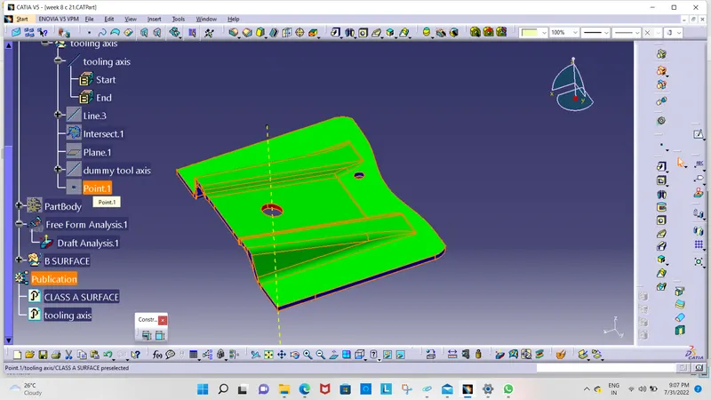
Week 8 - Challenge 1 - Base Bracket Design
AIM: Create the Base Bracket Plastic component through the given Class-A surface. To begin with, the tooling axis for the given Class-A Surface should be created meeting the requirements of the draft angle and at the end perform the Draft analysis on the model.
objective:
- Tree Structure
- Ensure Proper Tree Structure
- Geometrical sets should have a proper name based on the sketches present inside of it
- All the sketches should be created under the Geometrical set
- Use the Close Surface feature to make a solid body from the surface.
- Publications: Use the publication option and publish the below
- Tooling Axis
- Class A, B, and C surface
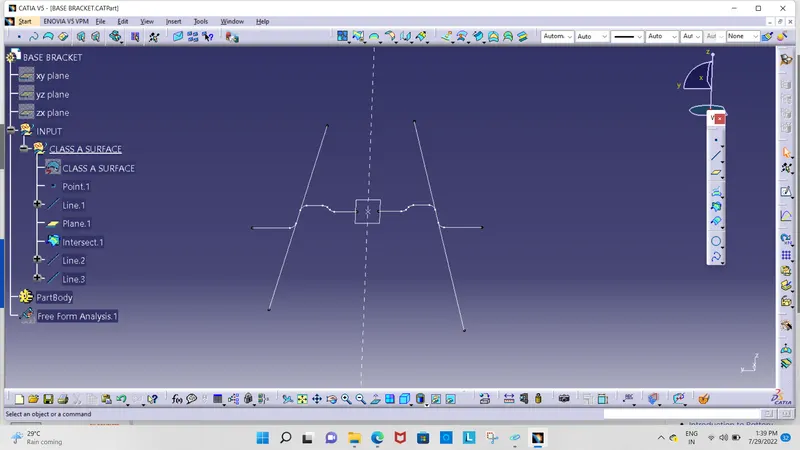
class A surface :
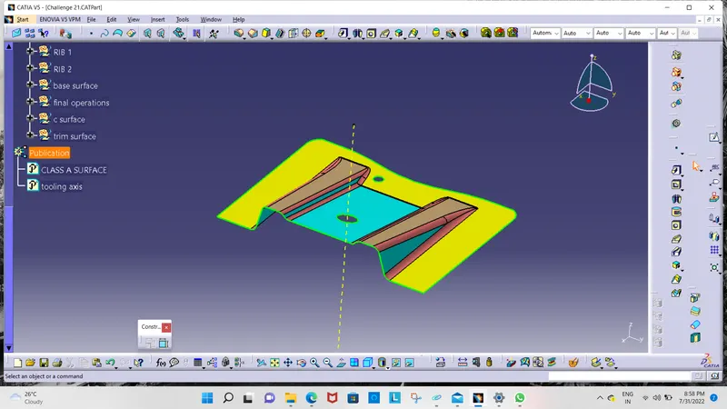
after this find out the tooling axis
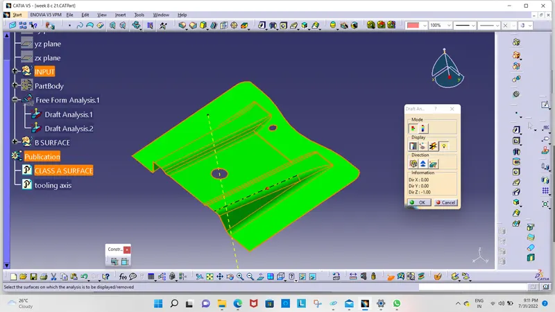
Draft Analysis for Surface A:
The analysis is done for a 3degree draft. So as can be seen all the surfaces are more than 3deg.
Creating of Tooling Axis:
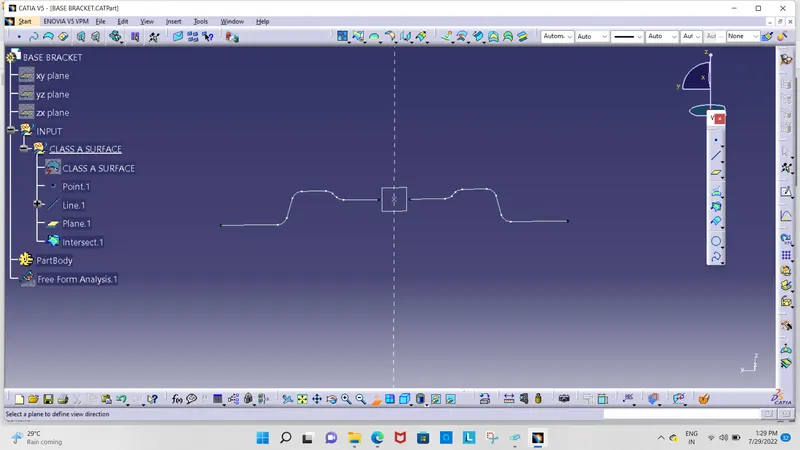
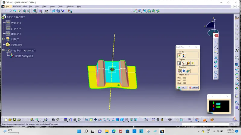
the yellow line is our tooling axis
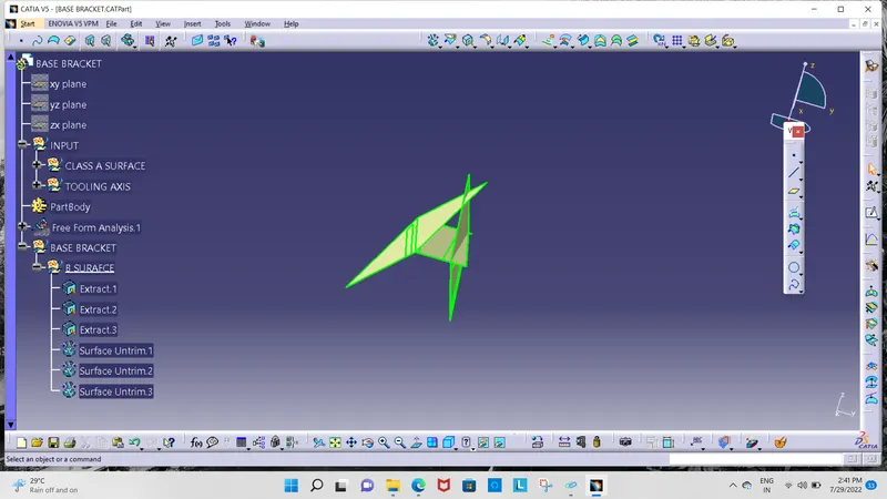
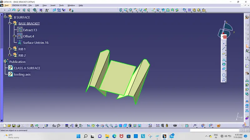
Creation of Class B:
- Now for Class B creation, we have extracted surfaces from Class A and untrimmed them to obtain the original parent surface.
- These surfaces are then offset to the required thickness.
- After offsetting, all the surfaces are trimmed into the required shape.
- Required fillets are given to the surfaces.
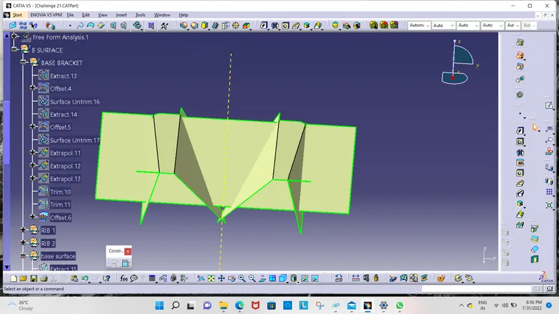
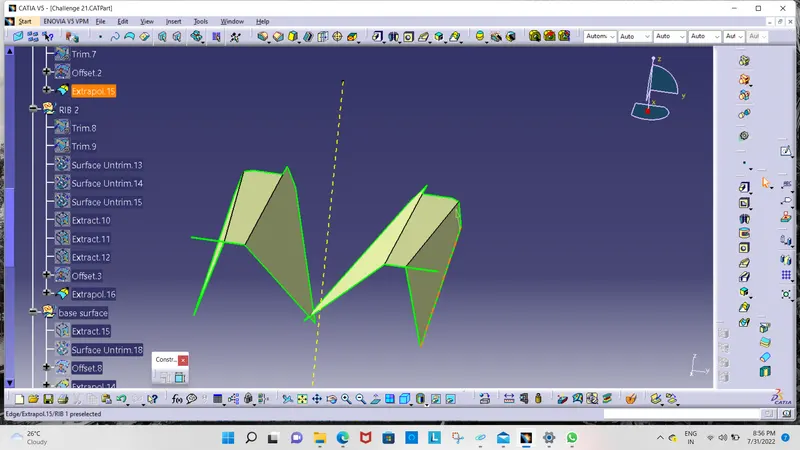
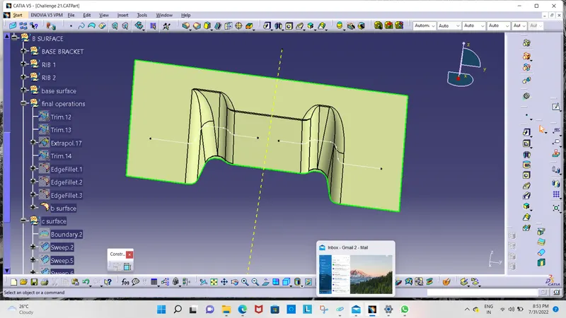
Creation of Class C:
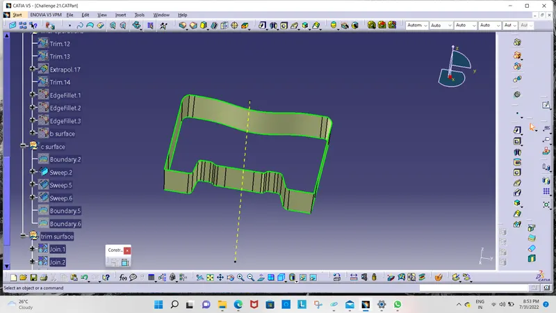
Final Trims:
Class A + Class C:
To make sure that there is not any open boundary between class A and class C, we have used the join option to create the single body. This is done to make sure that the parting line doesn't lie between these two surfaces.
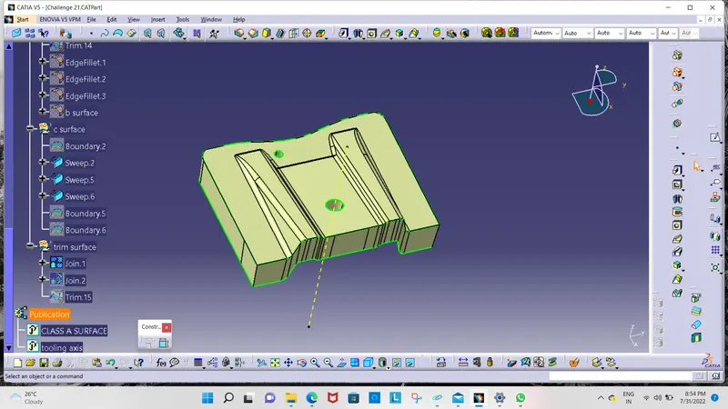
Class A + Class B + Class C:
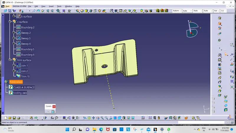
Draft analysis on final component: