Week 8 - Challenge 1 - Base Bracket Design
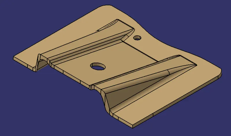
AIM: Create the Base Bracket Plastic component through the given Class-A surface. To begin with, the tooling axis for the given Class A Surface should be created meeting the requirements of the draft angle and at the end perform the Draft analysis on the model.
Given Class A Surface:
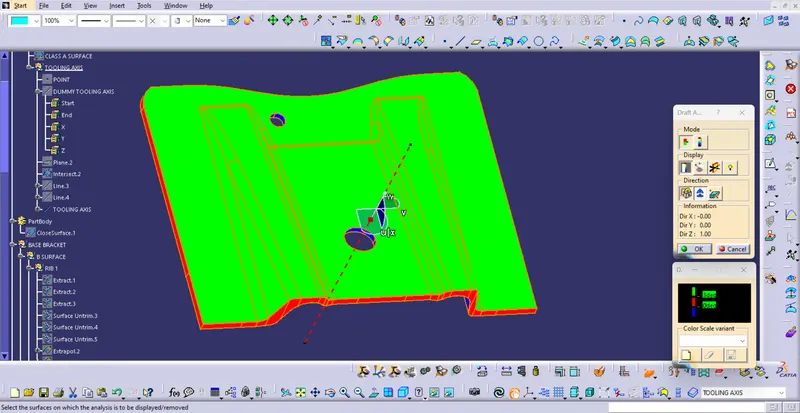
Draft analysis
Draft allows for the component to release from the mould, most parts or applications require a minimum of 0.5 to 1 degree draft angle and 3 dgree draft angle is widely used as per the norm.
Change the matrrial mode to customize mode before moving to the draft analysis.Insert –analysis-feature draft analysisDefining the draft direction Select draft analysis from the tool bar and click on the compass symbol and pull the compass from the right side top corner of the workbench and place it on the component where want to do the draft analysis. ‘W’ of the compass and tooling axis should be aligned on the same line.By clicking the on the surface and using the flipping tool we can assign the Flipping direction .
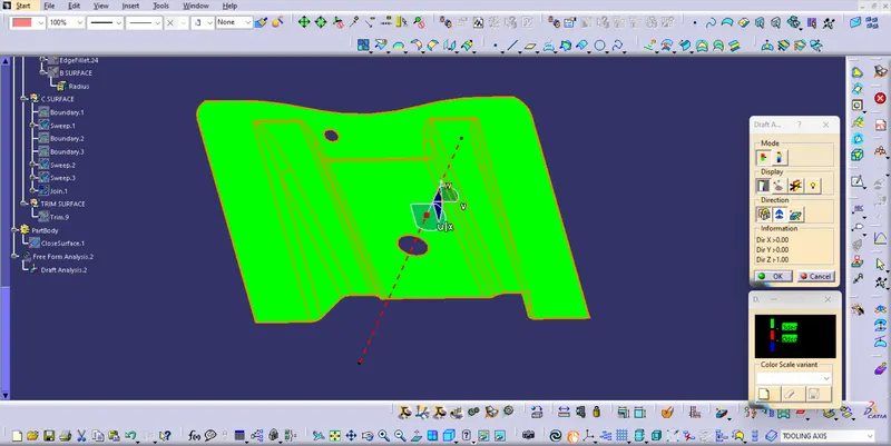
Click on the lock symbol and click on the component then a table will appear it shows the draft value.Analysis under running point and move the mouse on the surface and it will show the details of the surface deg direct.
Tooling Axis
The direction in which the mould open and closes is the tooling axis.
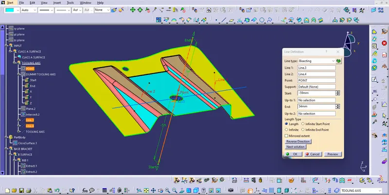
Check the connectivity of the surface and ensure there will be no gap between the surfaces and then define the tooling axis.While creating a tooling axis give the tooling axis on a flat length surface or the surface which have a hole on it.Create a point on the surface where we are going to create the dummy tooling axis and using line command crate an axis. If there is a circle or flat length surface which is recommended.
Creating B surface :
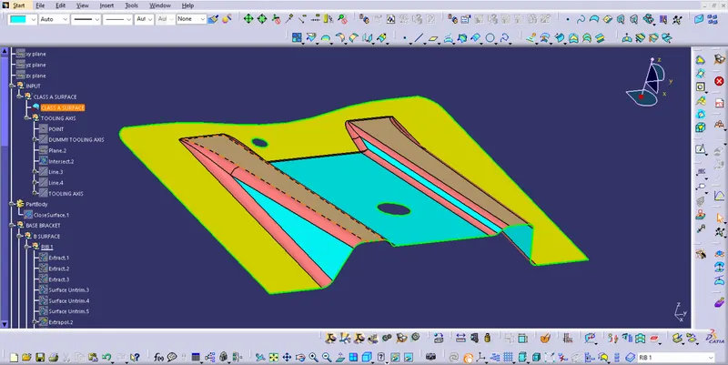
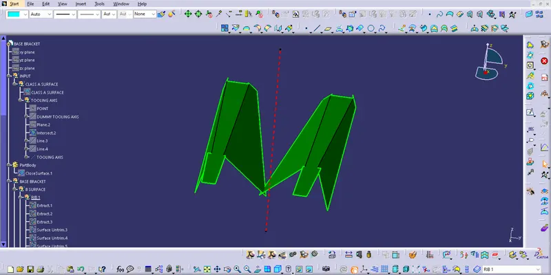
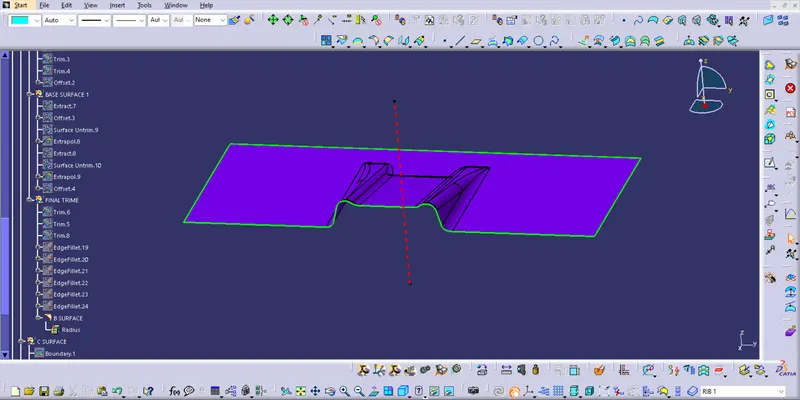
B surface should be inside the class A surface.Class A is an aesthetics surface and class B is an engineering surface.B surface can be created by three steps by ribs and the base.First step is to create the Ribs by extracting the required surface from Class A and untrim it thus we will get the six individual surfaces and extrapolated all and trim it to get the required shape and finally offset it by the required thickness.
- RIB
- FINAL TRIM
Creating C surface :
C surface has been created from with reference to the boundary lines of class A surface and sweep it with reference to the tooling axis then the holes are created by following the same method.
Then join C surfaces and holes with class A surface.Finally trimmed the join with B surface to get the final compenent.By using the final Trim Create the solid body by using close surface on part workbench.
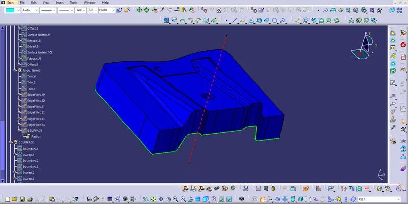
Final Trim Surface :
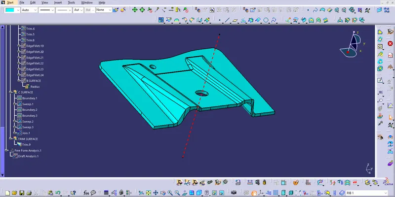
Draft analysis of Final Trim Surface :
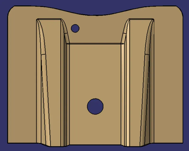
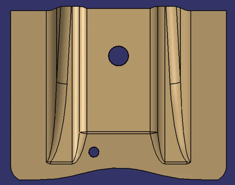
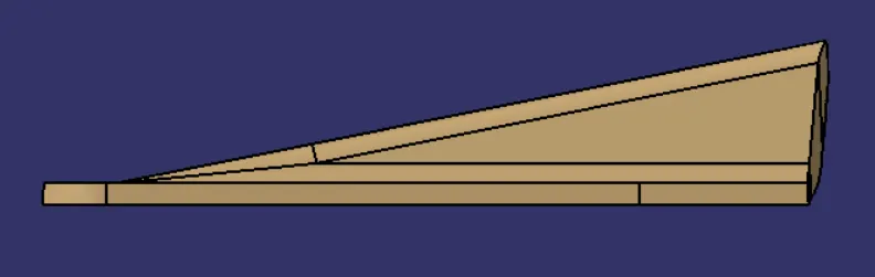
Different 3D Views of a Component :
TOP VIEW :
BOTTOM VIEW :
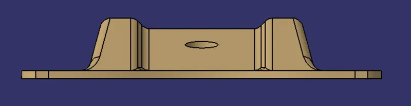
SIDE VIEW :
FRONT VIEW :
ISOMETRIC VIEW :