Week 8 - Challenge 1 - Base Bracket Design
OBJECTIVE
To create base bracket plastic component from the given class- A surface.
To create the tooling axis for the plastic component
To perform draft analysis over the plastic component.
Create the Base Bracket Plastic component through the given Class-A surface
1. Explaining the draft analysis and the tooling axis creation-
The part can easily eject from the mould thanks to the Draft. The draft angle helps to prevent damage by reducing friction between the core, cavity, and part. The smallest draft angle that can be used in a plastic design is 0.5 degrees, while 3 degrees is the most commonly used in plastic design.
When performing a draft analysis in CATIA, zones on the analysed element are identified by colour ranges where the deviation from the draft direction at any point corresponds to predetermined values.
The primary factor to take into account when designing a plastic component is tooling direction. The option is provided in the moulding machine to open the mould in that direction. It determines which way the cavity and core open.
STEP 1 - TOOLING AXIS CREATION
Determine the best direction for the tooling axis by manually analysing the model or visually examining it.
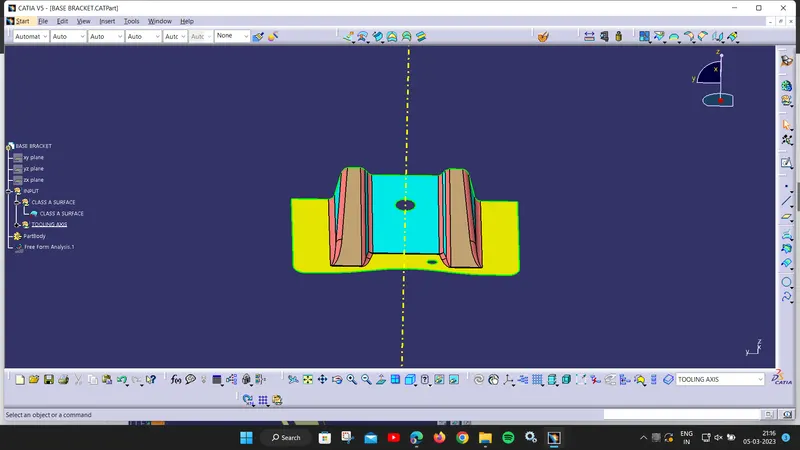
We can directly take the tooling axis perpendicular to that since the 3D image shows 2 holes and a smooth surface. But let's analyse from all angles just to be sure. The front side and top views of the images below indicate the points to consider while selecting a tooling axis. We cannot take an axis along this since from X we cannot see a single hole. Since we cannot detect any holes in Y, we are also unable to determine the tooling axis. However, in Z there are two holes and a smooth surface, thus we can determine the tooling axis.
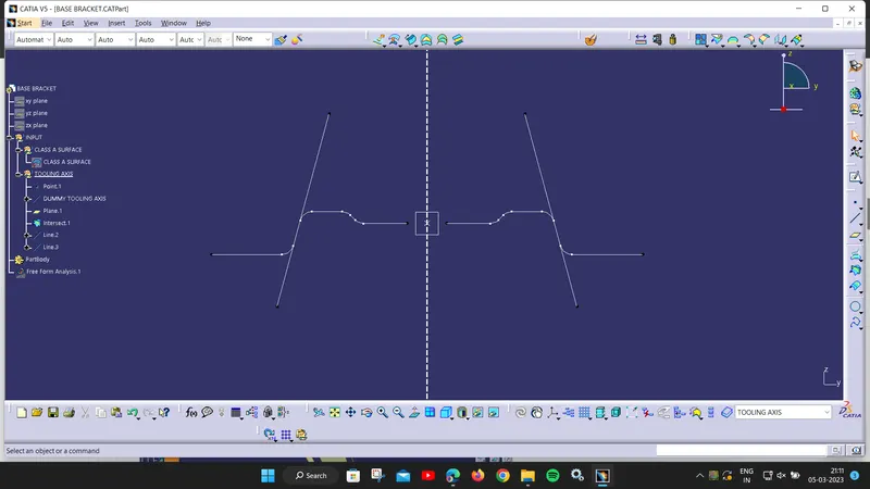
There are no surfaces that could cause issues during tooling in this direction when the ZX plane of the axis system is intersected with the input, as can be seen.
We don't know how these two surfaces intersect the ZY plane, so we draw a line through them both to determine the tooling axis, which, not surprisingly, coincides with our guessed tooling axis.
STEP 2 - CLASS A DRAFT ANALYSIS
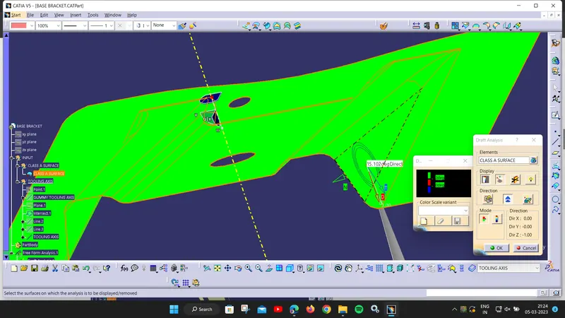
- Go to the draft analysis in analysis feature.
- Align the compass along the tooling axis.
- Click the surface to verify that it is within the draft values' permitted range.
- The surface should be green, and the correct value (3 degrees) should be entered in the column.
STEP 3 - CREATING CLASS B SURFACE
- Using the extract option on the Class A surface to firstly extract the right side rib.
- Extrapolate is then used to extend the length.
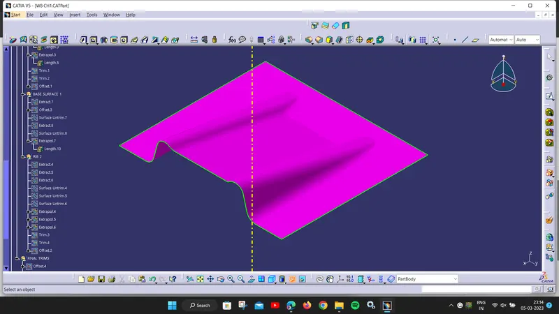
- Trim the surfaces now to the appropriate surfaces.
- Then, offset the surface to obtain the necessary thickness.
- Create the left side rib similarly.
- Similarly, obtain the flat and slanted surfaces and offset them to the appropriate value.
- And now, trim to achieve the desired surface.
- Fill up the surface now as necessary.
STEP 4- CREATING SURFACE C
a) Extract the boundary of the class-A surface.
b) On the class-A surface, determine the hole's perimeter.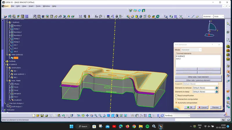
Utilize the sweep command on each boundary individually to obtain the class-C surface.
STEP 5- Joining the class-A and class-C surfaces together
STEP 6- Trim the class-B surface with the join created earlier
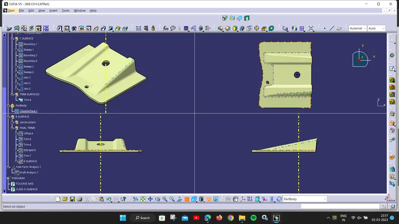
CLOSED SURFACE:
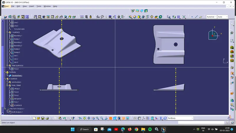
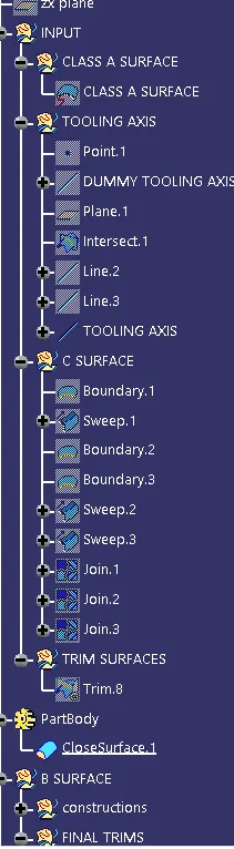
DESIGN TREE: