Week 10 - Challenge 1- Attachment Feature Creation (Ribs & Screw Boss)
OBJECTIVE:
To Create Closed Body for given Door Handle Class A surface and also, Create the Rib & Screw Boss for the Door Handle considering the design rules.
STEPS FOLLOWED:
- Tooling Axis Creation.
- Draft Analysis of Class A surface.
- Creating Class B surface and Class C surface.
- Creating a Closed body of component Door Handle.
- Draft analysis for Door Handle Component.
- Creating the Sketches of Ribs & Screw Boss profile as per the given guidelines.
- Solid Profile creating for the Ribs & Screw Bosses using Thick Surface and Pad Commands. Added them to the Closed Partbody.
- Given the Draft angle and Edge Fillet Radius to the require faces as per the Guidelines.
- Check the parameters of Ribs & Screw Bosses that were is per Guidelines and standarts.
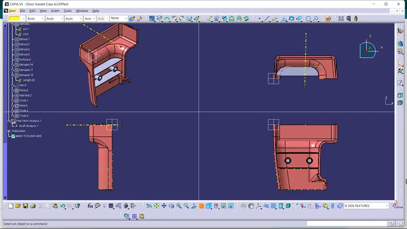
- Perform the Draft Analysis for Ribs and Screw Bosses Assembly.
Commands used Boundary, Extract, Multiextract, Trim, Join, Sweep, Point, Line, Bisection Line, Circle , Draft, Edge Fillet, Draft Analysis, Closed Body, Thick Surface, Pad, Unitrim, Remove, Intersection.
Key Terms:
TOOLING AXIS:
- It is the direction of Mold's Core & Cavity moves.
- The Tooling Direction is basically the direction that the mold pulls apart.
- The mold is built in two separate pieces, Cavity side & Core side.
- The Core pulls apart from the Cavity and that's the Tooling Direction.
- The Line of Direction or Axis followed is Tooling Axis.
CLASS A SURFACE:
- Class A surface means Visible surface of the Component or part.
- It is the base reference to the creation of B & C surfaces that forms the Component.
- It provides the Aesthetic Appreance to the component.
CLASS B SURFACE:
- It is the mostly the Non-Visible Surface area
- It is the behind the Class A surface .
- It helps in the Parting surface creation.
- Flashes and Missmatches are done in the Class B surface , that will not distrub the Class A surface.
CLASS C SURFACE:
- It connetcs the Class A surface and Class B surface of the component.
- It also describes the Thickness of the Component.
DRAFT ANALYSIS:
- The draft analysis technique is used to analyze whether our part model created is manufacturable or not.
- Based on the Draft condition and Tooling Axis applied, Here the part should get easily removed from the Mold (Core & Cavity).
RIBS
- Ribs are thin extensions that run perpendicular from a wall or plane.
- These used to provide additional support and strength to a part.
- Ribs are used to strengthen the walls of your mould without increasing wall thickness.
- Ribs minimise the problems that come into play when the wall thicknesses have to be increased.
- These also reduce the Defects of wall is too thick, warping and sinking that can result the entire design may need to be rejected.
SCREW BOSSES:
- Screw Bosses are typically used to assist in assembly, as a receptacle for a screw or threaded insert or as the locator.
- Bosses are protuberances on a plastic part designed to add strength, to facilitate alignment during assembly, to provide for fastening, etc.
PROCEDURE:
- Checked the Class A surface is a Closed profile by using the Boundary command.
- The complete profile has only one Boundary at the outer edge without breakage.
Checking the given Class A Surface.
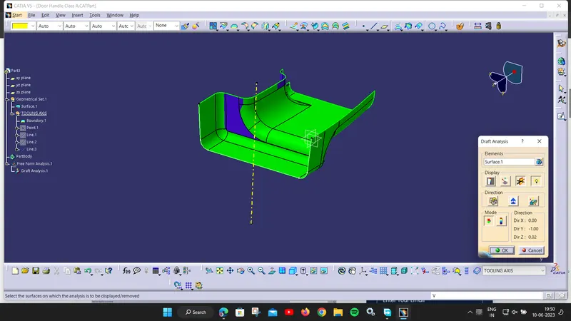
DRAFT ANALYSIS(CLASS A):
- Select into the Material Mode and Insert the Feature Draft Analysis.
- Select the Compass place in the Tooling Axis Direction and Activate the Compass , adjust the compass to the Tooling Axis Direction.
- Provide the Minimum Draft angle is 3Deg or 2.9Deg.
- Select the surface So that the Green Area is more than 3Deg draft angle and it is manufacturable.
TOOLING AXIS:
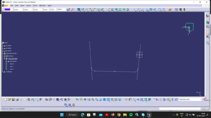
- Checked the all the posibilites of Draft Tooling Axis in all directions so that the most of the surface area visible
- Confirmed that the it would be in Y direction.
- Created a point on Profile and created a line in Y direction as the Dummy Tooling axis.
- Now the Lines are picked from the walls of the Door Handle that are Parllel to the Dummy Tooling Axis.
- Bisecting the Lines with eachother at the Point on surface .
- The formed Bisected Line is Cross Checked as Tooling Axis in the Draft analysis for the Best results.
- The Bisection line that cleares most region and with out Negative Draft angle will be the Final Tooling Axis.
- The Draft Analysis for the Different lines are mentioned bellow
X-Direction
Creating Class B Surface:
Class B surface is mostly the not visible surface and it is the back of the Class A surface.
- Offset the Class A surface for 3mm (Thickness of Component is 3mm).
- The offset surface has the Patches that the minimum fillet value placess cant be offset.
- Checked the posibilites of the Extract the Individuall surface, Untrimed, Extrapolated and trimed them but it is profile is not matching with the base profile.
- Extacted the Complete Profile and the and trimed them but the fillet values are not matched.
- The simple method is done by using the Multi Section Surface.
- Created the Boundary on the Two sides of the profile and Multi-Section Surface command is used.
- The obtained Profile is Joined with the Offset Profile.
- The profile is closed completely with out gap or patches and the edges are formed on it.
- The B surface exterior is Extrapolated in boundary for the Trim with Class A and C surface.
Class C Surface:
Class C Surface is that connect the Class A Surface and Class B Surface.
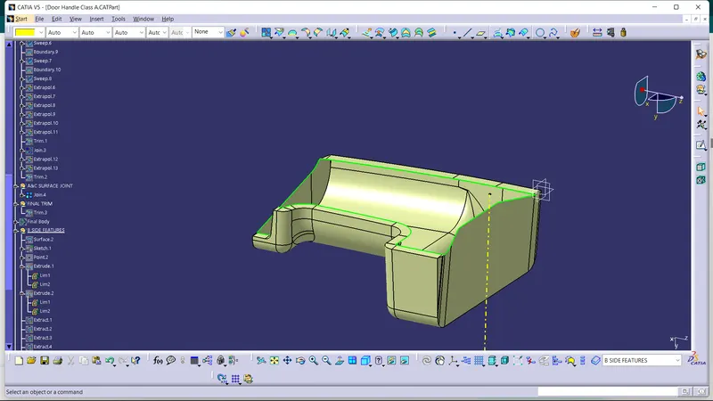
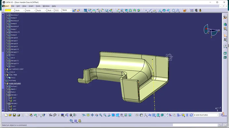
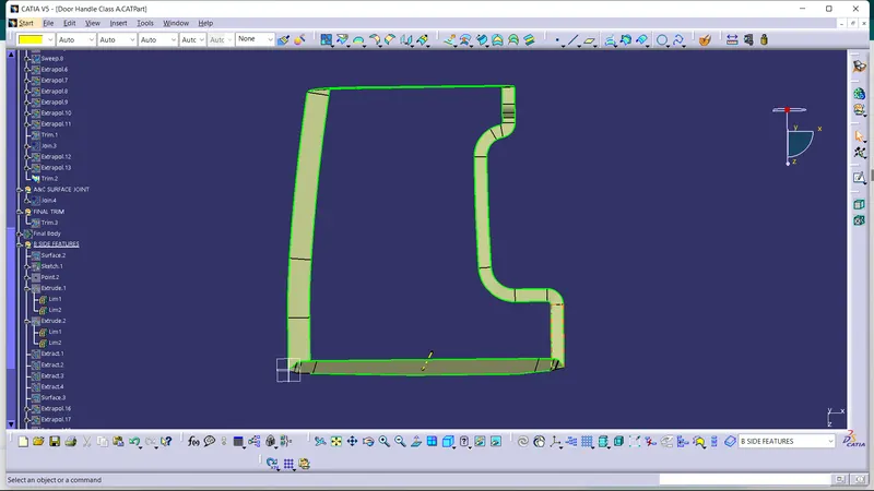
- Create a boundary on the Class A surface and then Sweep it.
- By using the Sweep Command with the reference of Class A surface and angle of 87Deg to it (the 3deg will give the Draft clearence while manufacturing).
- Then the Class C surface is Joined with Class A surface by using the Join Command.
- The thickness or length of the Class C Surface is 8mm minimum so that it will be trimed easily with Class B surface.
- Now the Joined Class A & C Surace is trimmed with the Class B surface.
CLOSED SURFACE:
- The Trimed surface is formed.
- Created a boundary on the Trimed Surface so that it inssures that no boundary formed.
- Confirms that it is completely closed.
- By using the Closed surface Command in the Part Body Design to the surface body.
- Now the Solid Body is formed.
RIBS CREATION:
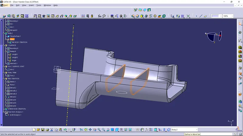
- Extract the B surface from the Trimed profile.
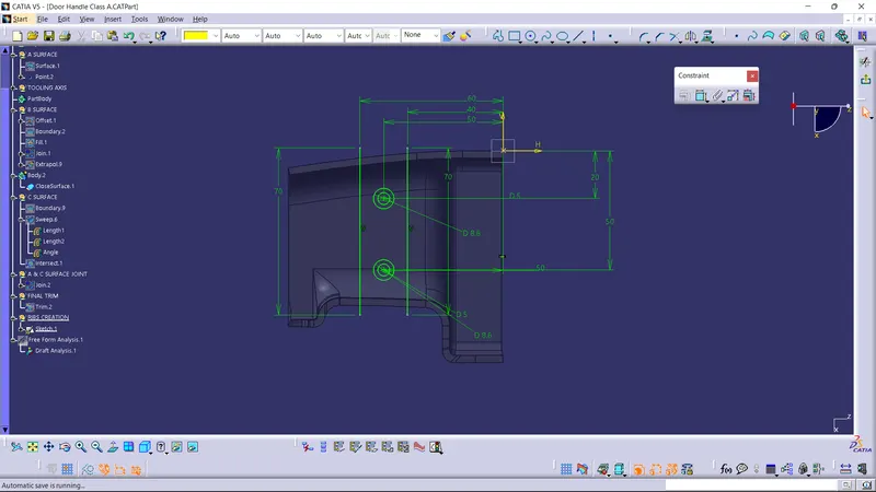
- Select the Extracted surface as the Reference Plane and Orgin point as the projection point in the Positioned Sketch.
- Create a line on the surface and give the approriate dimensions to it.
- The distance between is also provided to it.
- Now the Lines as the Output Feature for easy acess.
- Extrude the Line in Tooling Axis Direction as a height of 13mm (Height <5*thickness of component, H<2.5*5=12.5).
- By Thicken the Extruded surface at 1mm Thickness by Thick Surface Command in Part Body(Thickness = 40% of thickness of component, =0.4*2.5mm, =1mm)
- Unitrim the Ribs with the Closed Body to remove the Excess Profile at the bottom side on Class A surface.
- Similarly done for the other Rib also.
SCREW BOSSES DESIGN:
- The circles are Drawn on the Extracted Plane.
- The dimension is taken as the 5mm diameter ie. M6 Diameter is 5.2mm.
- so the outer radius is 5.2+3=8.2mm.
- The Height should be 3:1 ratio diameter to height. the diameter is 5mm so the height is 12mm.
- The Outer and Inner Profiles are Output feature.
- The Both profiles are extraced by Pad command.
- The outer Profile is Added to the Part Body.
- The Inner Profile is Removed to The Part Body.
- The Dimensions of the Ribs & Screw Bosses as per the Guidelines are mentioned below.
DRAFTING ANALYSIS(FINAL OUTPUT):
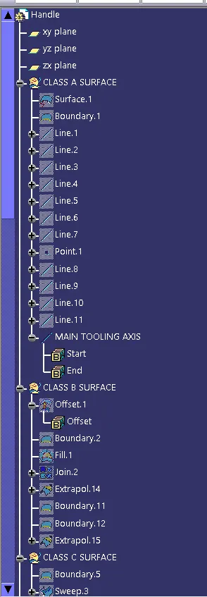
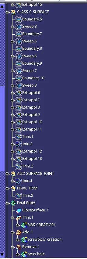
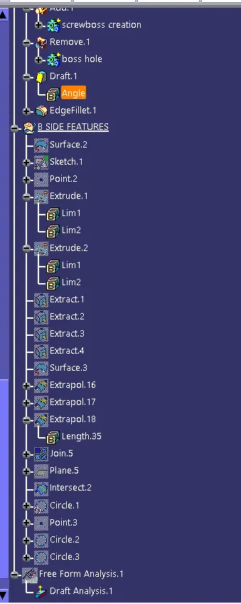
Tree structure: