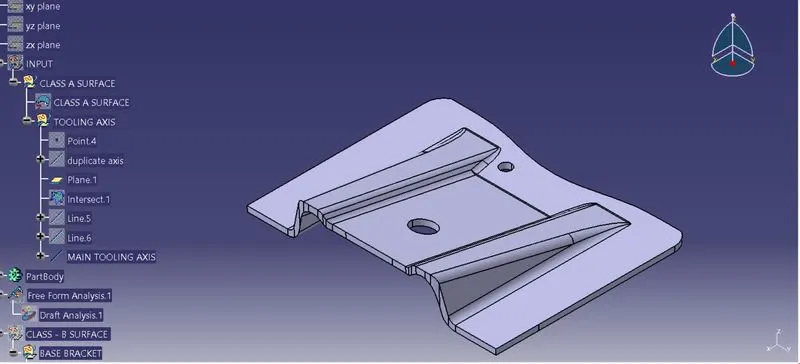
Week 8 - Challenge 1 - Base Bracket Design
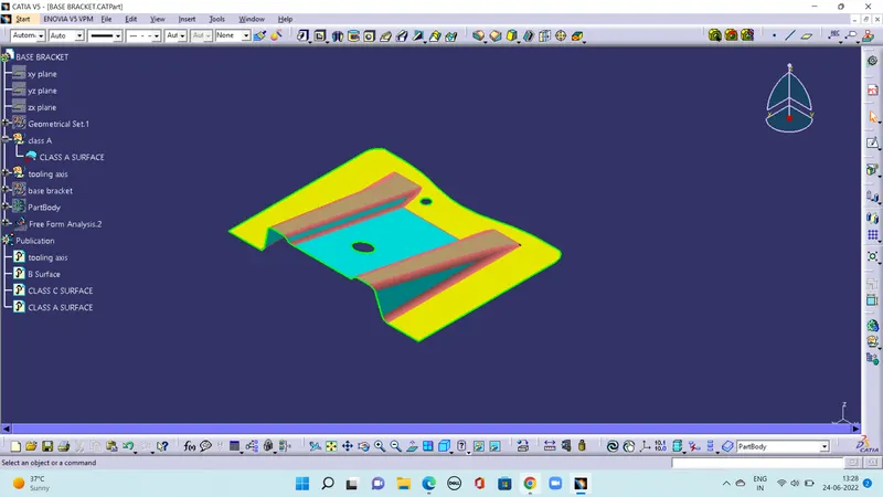
Check the connectivity of the Class A Surface
Ensure that there is no gap between the component, using the join command.
We can visually check it or by clicking the boundary command.
It has 3 boundaries one outer and two inner circle boundaries.
Therefore first check was completed. Find the tooling axis of the component. The tooling axis is nothing but the mold opens or the cavity opens. Check visually which is the best possible tooling axis. Check all three axes. Along x it is possible but expensive and y is not possible.
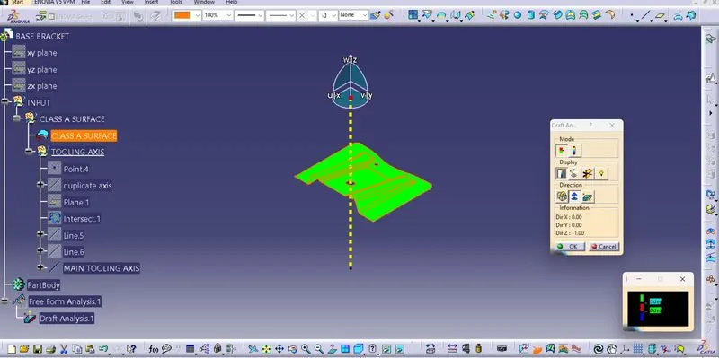
z is the best possible tooling axis. Creating a Tooling axis along z Therefore the main tooling axis is along the z-axis Now perform the Draft analysis using the Featured Draft Analysis tool in the tools Then after opening the draft analysis toolbox go for the compass and place the compass aligned to the tooling axis and click on the lock symbol after aligning and further click on the surface.
Now create a Class B Surface Initially extract the right side rib using the extract option from the Class A surface Then perform Extrapolate to increase the length Now trim the surfaces to the required surfaces Then Offset the surface to get the required thickness Similarly create a left side rib Now Similarly get the slanted as well as the flat surface and offset it to desired value And now trim to get the required surface Now fillet the surface to required amount now Creating Class C Surface EXPLANATION ON BISECTING METHOD:
Bisecting method is used to find the proper tooling axis using the dummy tooling axis. In Bisecting method, the bisecting line is used which either bisects the two lines or it will show an error which means the two lines are parallel to each other. To know whether the particular surface is tolerable or not we intersect the surface with the respective plane and get a sketch that consists of two lines with the help of bisecting line option we bisect the line which creates a line at the midpoint of the two lines. Likewise, we create a tooling clearing axis for x and y which will be used to create the main tooling axis using the bisecting line option in the line command