Week 8 - BlockMesh Drill down challenge
Aim:
To find the change in velocity magnitude profile with respect to simple grading factors for the given geometry.
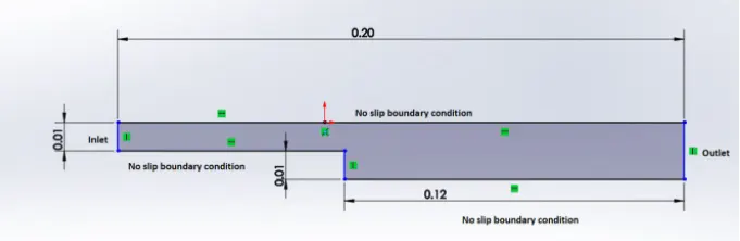
Mesh Specifications:
- Number of cells along the x-direction (longer dimension) = 200
- Number of cells along the y-direction = 10
- Use a graded mesh. The grading factor near all walls should be 0.2, 0.5, 0.8 in each case respectively.
Procedure:
1. To create the geometry and meshing:
In order to create the desired geometry and mesh, select any one of the case setups from the Openfoam tutorials and edit the blockMeshDict file. In this study, the cavity case setup from the incompressible tutorials is chosen. Then the vertices and the blocks are modified. Finally, the boundary faces are defined.
OpenFOAM code for geometry creation and meshing:
blockMeshDict:
/*--------------------------------*- C++ -*----------------------------------*\
  =========                 |
  \\      /  F ield         | OpenFOAM: The Open Source CFD Toolbox
   \\    /   O peration     | Website:  https://openfoam.org
    \\  /    A nd           | Version:  8
     \\/     M anipulation  |
\*---------------------------------------------------------------------------*/
FoamFile
{
    version     2.0;
    format      ascii;
    class       dictionary;
    object      blockMeshDict;
}
// * * * * * * * * * * * * * * * * * * * * * * * * * * * * * * * * * * * * * //

convertToMeters 0.001;

vertices
(
    (0 0 0)
    (80 0 0)
    (80 5 0)
    (0 5 0)
    (80 10 0)
    (0 10 0)
    (200 10 0)
    (200 5 0)
    (200 0 0)
    (200 -10 0)
    (80 -10 0)
    (0 0 10)
    (80 0 10)
    (80 5 10)
    (0 5 10)
    (80 10 10)
    (0 10 10)
    (200 10 10)
    (200 5 10)
    (200 0 10)
    (200 -10 10)
    (80 -10 10)
);

blocks
(
    hex (0 1 2 3 11 12 13 14) (200 10 1) simpleGrading (1 5 1)
    hex (3 2 4 5 14 13 15 16) (200 10 1) simpleGrading (1 0.2 1)
    hex (2 7 6 4 13 18 17 15) (200 10 1) simpleGrading (5 0.2 1)
    hex (1 8 7 2 12 19 18 13) (200 10 1) simpleGrading (5 5 1)
    hex (10 9 8 1 21 20 19 12) (200 10 1) simpleGrading (5 5 1)
);

edges
(
);

boundary
(
  inletwall
  {
   type patch;
   faces
   (
        (0 11 14 3)
        (3 14 16 5)
   );
  }

  outletwall
  {
   type patch;
   faces
   (
        (9 8 19 20)
        (8 7 18 19)
        (7 6 17 18)
   );
  }

  frontandback
  {
   type empty;
   faces
   (
        (11 12 13 14)
        (14 13 15 16)
        (13 18 17 15)
        (12 19 18 13)
        (21 20 19 12)
        (0 3 2 1)
        (3 5 4 2)
        (2 4 6 7)
        (1 2 7 8)
        (10 1 8 9)
   );
  }

  topwall
  {
   type wall;
   faces
   (
        (5 16 15 4)
        (4 15 17 6)
   );
  }

  bottomwallone
  {
   type wall;
   faces
   (
        (0 1 12 11)
   );
  }

  bottomwalltwo
  {
   type wall;
   faces
   (
        (10 9 20 21)
   );
  }

  sidestep
  {
   type wall;
   faces
   (
        (1 10 21 12)
   );
  }
);

mergePatchPairs
(
);

// ************************************************************************* //
Initially, a simple grading factor of 0.2 is used.

2. To modify the solver setup:
The transportProperties file present in the "constant" folder is modified to set the kinematic viscosity of the desired fluid. For water at 20C, the value of kinematic viscosity is 1e-6 `m^2/s`
transportProperties:
/*--------------------------------*- C++ -*----------------------------------*\
  =========                 |
  \\      /  F ield         | OpenFOAM: The Open Source CFD Toolbox
   \\    /   O peration     | Website:  https://openfoam.org
    \\  /    A nd           | Version:  8
     \\/     M anipulation  |
\*---------------------------------------------------------------------------*/
FoamFile
{
    version     2.0;
    format      ascii;
    class       dictionary;
    location    "constant";
    object      transportProperties;
}
// * * * * * * * * * * * * * * * * * * * * * * * * * * * * * * * * * * * * * //

nu              [0 2 -1 0 0 0 0] 1e-6;


// ************************************************************************* //
fvSchemes:
/*--------------------------------*- C++ -*----------------------------------*\
  =========                 |
  \\      /  F ield         | OpenFOAM: The Open Source CFD Toolbox
   \\    /   O peration     | Website:  https://openfoam.org
    \\  /    A nd           | Version:  8
     \\/     M anipulation  |
\*---------------------------------------------------------------------------*/
FoamFile
{
    version     2.0;
    format      ascii;
    class       dictionary;
    location    "system";
    object      fvSchemes;
}
// * * * * * * * * * * * * * * * * * * * * * * * * * * * * * * * * * * * * * //

ddtSchemes
{
    default         Euler;
}

gradSchemes
{
    default         Gauss linear;
    grad(p)         Gauss linear;
}

divSchemes
{
    default         none;
    div(phi,U)      Gauss linear;
}

laplacianSchemes
{
    default         Gauss linear orthogonal;
}

interpolationSchemes
{
    default         linear;
}

snGradSchemes
{
    default         orthogonal;
}


// ************************************************************************* //
fvSolution:
/*--------------------------------*- C++ -*----------------------------------*\
  =========                 |
  \\      /  F ield         | OpenFOAM: The Open Source CFD Toolbox
   \\    /   O peration     | Website:  https://openfoam.org
    \\  /    A nd           | Version:  8
     \\/     M anipulation  |
\*---------------------------------------------------------------------------*/
FoamFile
{
    version     2.0;
    format      ascii;
    class       dictionary;
    location    "system";
    object      fvSolution;
}
// * * * * * * * * * * * * * * * * * * * * * * * * * * * * * * * * * * * * * //

solvers
{
    p
    {
        solver          PCG;
        preconditioner  DIC;
        tolerance       1e-06;
        relTol          0.05;
    }

    pFinal
    {
        $p;
        relTol          0;
    }

    U
    {
        solver          smoothSolver;
        smoother        symGaussSeidel;
        tolerance       1e-05;
        relTol          0;
    }
}

PISO
{
    nCorrectors     2;
    nNonOrthogonalCorrectors 0;
    pRefCell        0;
    pRefValue       0;
}


// ************************************************************************* //
3. To set the initial conditions:
The p and U files in the 0 folder are modified to set the desired initial conditions for pressure and velocity.
Let us assume a fixed velocity of 0.02 m/s.
p value:
/*--------------------------------*- C++ -*----------------------------------*\
  =========                 |
  \\      /  F ield         | OpenFOAM: The Open Source CFD Toolbox
   \\    /   O peration     | Website:  https://openfoam.org
    \\  /    A nd           | Version:  8
     \\/     M anipulation  |
\*---------------------------------------------------------------------------*/
FoamFile
{
    version     2.0;
    format      ascii;
    class       volScalarField;
    object      p;
}
// * * * * * * * * * * * * * * * * * * * * * * * * * * * * * * * * * * * * * //

dimensions      [0 2 -2 0 0 0 0];

internalField   uniform 0;

boundaryField
{
    inletwall
    {
        type            zeroGradient;
    }

    outletwall
    {
        type            fixedValue;
        value           uniform 0;
    }

    topwall
    {
        type            zeroGradient;
    }

    bottomwallone
    {
        type            zeroGradient;
    }

    bottomwalltwo
    {
        type            zeroGradient;
    }

    sidestep
    {
        type            zeroGradient;
    }

    frontandback
    {
        type            empty;
    }
}

// ************************************************************************* //
U value:
/*--------------------------------*- C++ -*----------------------------------*\
  =========                 |
  \\      /  F ield         | OpenFOAM: The Open Source CFD Toolbox
   \\    /   O peration     | Website:  https://openfoam.org
    \\  /    A nd           | Version:  8
     \\/     M anipulation  |
\*---------------------------------------------------------------------------*/
FoamFile
{
    version     2.0;
    format      ascii;
    class       volVectorField;
    object      U;
}
// * * * * * * * * * * * * * * * * * * * * * * * * * * * * * * * * * * * * * //

dimensions      [0 1 -1 0 0 0 0];

internalField   uniform (0 0 0);

boundaryField
{
    inletwall
    {
        type            fixedValue;
        value           uniform (0.02 0 0);
    }

    outletwall
    {
        type            zeroGradient;
    }

    topwall
    {
        type            noSlip;
    }

    bottomwallone
    {
        type            noSlip;
    }

    bottomwalltwo
    {
        type            noSlip;
    }

    sidestep
    {
        type            noSlip;
    }

    frontandback
    {
        type            empty;
    }
}

// ************************************************************************* //
At inlet and outlet walls one Dirichlet and one Neumann condition should be defined. For inlet ( Velocity U = 0.02 m/s; Pressure p = zeroGradient ); For outlet ( Velocity U = zeroGradient; Pressure p = 0 `m^2`/`s^2` )
4. To set the end time and time step:
The required time = `0.2/0.02 = 10 s`
The value of time step is assumed as `dT= 0.001`
These values are modified in the controlDict file present in the "system" folder.
controlDict:
/*--------------------------------*- C++ -*----------------------------------*\
  =========                 |
  \\      /  F ield         | OpenFOAM: The Open Source CFD Toolbox
   \\    /   O peration     | Website:  https://openfoam.org
    \\  /    A nd           | Version:  8
     \\/     M anipulation  |
\*---------------------------------------------------------------------------*/
FoamFile
{
    version     2.0;
    format      ascii;
    class       dictionary;
    location    "system";
    object      controlDict;
}
// * * * * * * * * * * * * * * * * * * * * * * * * * * * * * * * * * * * * * //

application     icoFoam;

startFrom       startTime;

startTime       0;

stopAt          endTime;

endTime         10;

deltaT          0.001;

writeControl    timeStep;

writeInterval   500;

purgeWrite      0;

writeFormat     ascii;

writePrecision  6;

writeCompression off;

timeFormat      general;

timePrecision   6;

runTimeModifiable true;


// ************************************************************************* //
5. To create the mesh and run the simulation:
blockMesh command is used to create the mesh for the given geometry. Once the mesh is created successfully, execute the icoFoam command in the terminal with the case setup file open in the run folder of OpenFOAM.

6. Results and Discussions:
Figure 1&2: Simple grading factor = 0.2
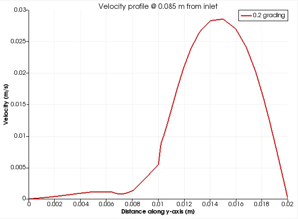
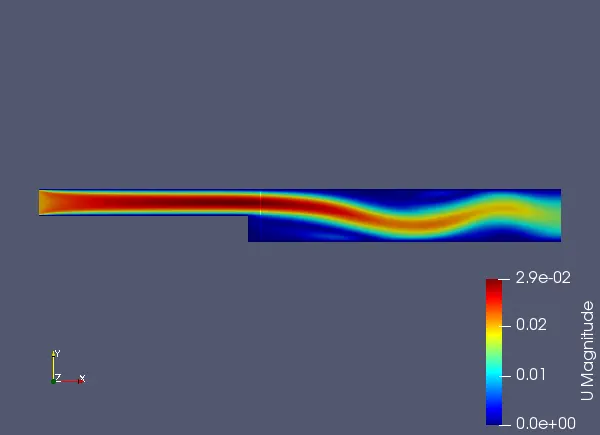
Figure 3&4: Simple grading factor = 0.5
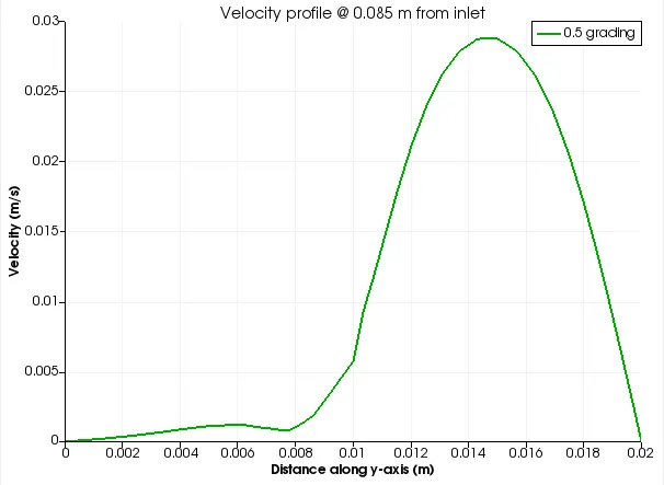
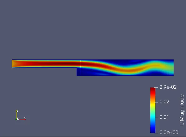
Figure 5&6: Simple grading factor = 0.8
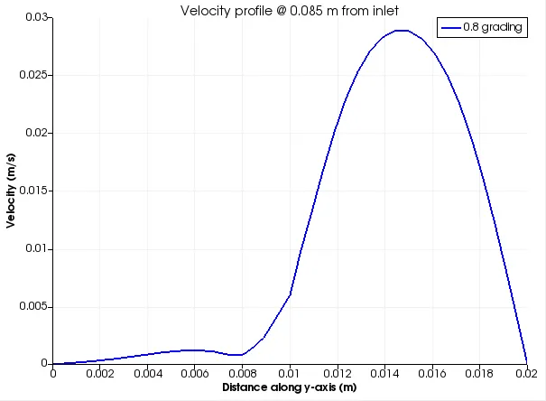
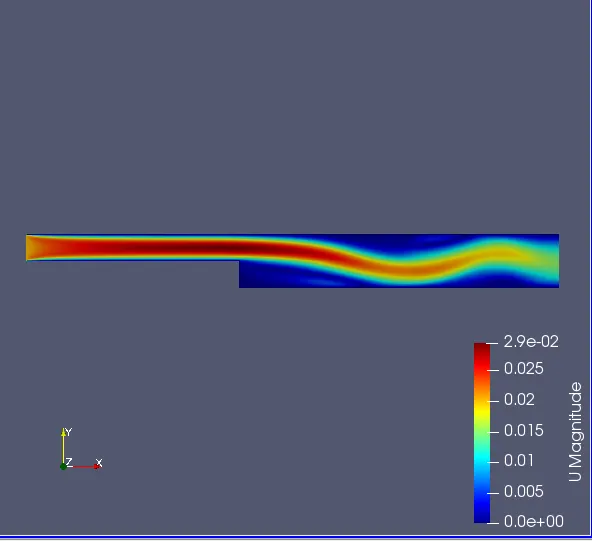
Figures 1,3,5 represent the line over the plot at the point 0.085 (just after the step region) for the grading factors 0.2, 0.5 & 0.8 respectively.
Figures 2,4,6 represent the contour plots of the velocity profile for the grading factors 0.2, 0.5 & 0.8 respectively.
It is evident from the contours obtained that the velocity increases at the step region with an increase in the grading factors (i.e 0.2, 0.5 & 0.8).
Also from the line over the plots, it is clear that the velocity magnitude curve at a particular distance is becoming more smooth with an increase in the grading factors (i.e 0.2, 0.5 & 0.8).