Week 8 - BlockMesh Drill down challenge
Aim:
- To generate the blockmesh file using openfoam and solve the problem with icoFoam solver.
- To compare the flow parameter by varying the grading factor of 0.2,0.5,0.8,1.
- To measure the flow parameter at the distance of 0.085m from inlet and analyze the results.
Results:
The given geometry is,
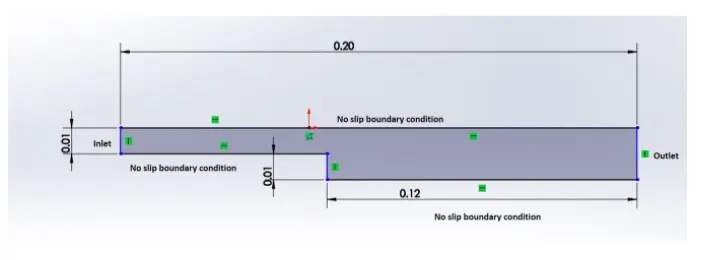
Fig.1 Geometry of the problem.
Number of cells along the x direction (longer dimension) = 200
Number of cells along the y direction = 10
Boundary condition:
Inlet- velocity - 1m/s
Outlet-pressure-atmospheric
Top & bottom - Wall
As it is laminar flow (`Re = (rho.v.D)/(mu)`) we used transient laminar solver icoFoam.
ControlDict file:
/*--------------------------------*- C++ -*----------------------------------*\
  =========                 |
  \\      /  F ield         | OpenFOAM: The Open Source CFD Toolbox
   \\    /   O peration     | Website:  https://openfoam.org
    \\  /    A nd           | Version:  8
     \\/     M anipulation  |
\*---------------------------------------------------------------------------*/
FoamFile
{
    version     2.0;
    format      ascii;
    class       dictionary;
    location    "system";
    object      controlDict;
}
// * * * * * * * * * * * * * * * * * * * * * * * * * * * * * * * * * * * * * //

application     icoFoam;

startFrom       startTime;

startTime       0;

stopAt          endTime;

endTime         0.35;

deltaT          0.00005;

writeControl    timeStep;

writeInterval   20;

purgeWrite      0;

writeFormat     ascii;

writePrecision  6;

writeCompression off;

timeFormat      general;

timePrecision   6;

runTimeModifiable true;


// ************************************************************************* //
BlockMesh dict file:
/*--------------------------------*- C++ -*----------------------------------*\
  =========                 |
  \\      /  F ield         | OpenFOAM: The Open Source CFD Toolbox
   \\    /   O peration     | Website:  https://openfoam.org
    \\  /    A nd           | Version:  8
     \\/     M anipulation  |
\*---------------------------------------------------------------------------*/
FoamFile
{
    version     2.0;
    format      ascii;
    class       dictionary;
    object      blockMeshDict;
}
// * * * * * * * * * * * * * * * * * * * * * * * * * * * * * * * * * * * * * //

convertToMeters 0.01;

vertices
(
    (0 0 0)//0
    (8 0 0)//1
    (8 0.5 0)//2
    (0 0.5 0)//3
    (8 1 0)//4
    (0 1 0)//5
    (20 1 0)//6
    (20 0.5 0)//7
    (20 0 0)//8
    (20 -1 0)//9
    (8 -1 0)//10
    (0 0 0.1)//11
    (8 0 0.1)//12
    (8 0.5 0.1)//13
    (0 0.5 0.1)//14
    (8 1 0.1)//15
    (0 1 0.1)//16
    (20 1 0.1)//17
    (20 0.5 0.1)//18
    (20 0 0.1)//19
    (20 -1 0.1)//20
    (8 -1 0.1)//21
);

blocks
(
    hex (0 1 2 3 11 12 13 14) (200 10 1) simpleGrading (1 1 1)
    hex (3 2 4 5 14 13 15 16) (200 10 1) simpleGrading (1 1 1)
    hex (2 7 6 4 13 18 17 15) (200 10 1) simpleGrading (1 1 1)
    hex (1 8 7 2 12 19 18 13) (200 10 1) simpleGrading (1 1 1)
    hex (10 9 8 1 21 20 19 12) (200 10 1) simpleGrading (1 1 1)
);

edges
(
);

boundary
(
    inlet
    {
        type patch;
        faces
        (
            (0 11 14 3)
            (3 14 16 5)
        );
    }
    outlet
    {
        type patch;
        faces
        (
            (9 8 19 20)
            (8 7 18 19)
            (7 6 17 18)
        );
    }
    NoslipWalls
    {
        type wall;
        faces
        (
            (0 1 12 11)
            (5 16 15 4)
            (4 15 17 6)
            (10 21 12 1)
            (10 9 20 21)
        );
    }
    frontAndBack
    {
        type empty;
        faces
        (
            (0 3 2 1)
            (3 5 4 2)
            (2 4 6 7)
            (1 2 7 8)
            (10 1 8 9)
            (11 12 13 14)
            (14 13 15 16)
            (13 18 17 15)
            (12 19 18 13)
            (21 20 19 12)
        );
    }
);

mergePatchPairs
(
);

// ************************************************************************* //
Boundary condition file:
Pressure file:
/*--------------------------------*- C++ -*----------------------------------*\
  =========                 |
  \\      /  F ield         | OpenFOAM: The Open Source CFD Toolbox
   \\    /   O peration     | Website:  https://openfoam.org
    \\  /    A nd           | Version:  8
     \\/     M anipulation  |
\*---------------------------------------------------------------------------*/
FoamFile
{
    version     2.0;
    format      ascii;
    class       volScalarField;
    object      p;
}
// * * * * * * * * * * * * * * * * * * * * * * * * * * * * * * * * * * * * * //

dimensions      [0 2 -2 0 0 0 0];

internalField   uniform 0;

boundaryField
{
    inlet
    {
        type            zeroGradient;
    }

    outlet
    {
        type            fixedValue;
        value           uniform 0;
    }

    NoslipWalls
    {
        type            zeroGradient;
    }

    frontAndBack
    {
        type            empty;
    }
}

// ************************************************************************* //
Velocity file:
/*--------------------------------*- C++ -*----------------------------------*\
  =========                 |
  \\      /  F ield         | OpenFOAM: The Open Source CFD Toolbox
   \\    /   O peration     | Website:  https://openfoam.org
    \\  /    A nd           | Version:  8
     \\/     M anipulation  |
\*---------------------------------------------------------------------------*/
FoamFile
{
    version     2.0;
    format      ascii;
    class       volVectorField;
    object      U;
}
// * * * * * * * * * * * * * * * * * * * * * * * * * * * * * * * * * * * * * //

dimensions      [0 1 -1 0 0 0 0];

internalField   uniform (0 0 0);

boundaryField
{
    inlet
    {
        type            fixedValue;
        value           uniform (1 0 0);
    }

    outlet
    {
        type            zeroGradient;
    }

    NoslipWalls
    {
        type            noSlip;
    }

    frontAndBack
    {
        type            empty;
    }
}

// ************************************************************************* //
Finite volume scheme file:
/*--------------------------------*- C++ -*----------------------------------*\
  =========                 |
  \\      /  F ield         | OpenFOAM: The Open Source CFD Toolbox
   \\    /   O peration     | Website:  https://openfoam.org
    \\  /    A nd           | Version:  8
     \\/     M anipulation  |
\*---------------------------------------------------------------------------*/
FoamFile
{
    version     2.0;
    format      ascii;
    class       dictionary;
    location    "system";
    object      fvSchemes;
}
// * * * * * * * * * * * * * * * * * * * * * * * * * * * * * * * * * * * * * //

ddtSchemes
{
    default         Euler;
}

gradSchemes
{
    default         Gauss linear;
    grad(p)         Gauss linear;
}

divSchemes
{
    default         none;
    div(phi,U)      Gauss linear;
}

laplacianSchemes
{
    default         Gauss linear orthogonal;
}

interpolationSchemes
{
    default         linear;
}

snGradSchemes
{
    default         orthogonal;
}


// ************************************************************************* //
Finite volume solution file:
/*--------------------------------*- C++ -*----------------------------------*\
  =========                 |
  \\      /  F ield         | OpenFOAM: The Open Source CFD Toolbox
   \\    /   O peration     | Website:  https://openfoam.org
    \\  /    A nd           | Version:  8
     \\/     M anipulation  |
\*---------------------------------------------------------------------------*/
FoamFile
{
    version     2.0;
    format      ascii;
    class       dictionary;
    location    "system";
    object      fvSolution;
}
// * * * * * * * * * * * * * * * * * * * * * * * * * * * * * * * * * * * * * //

solvers
{
    p
    {
        solver          PCG;
        preconditioner  DIC;
        tolerance       1e-06;
        relTol          0.05;
    }

    pFinal
    {
        $p;
        relTol          0;
    }

    U
    {
        solver          smoothSolver;
        smoother        symGaussSeidel;
        tolerance       1e-05;
        relTol          0;
    }
}

PISO
{
    nCorrectors     2;
    nNonOrthogonalCorrectors 0;
    pRefCell        0;
    pRefValue       0;
}


// ************************************************************************* //
Grading results:
0.2 grading:
Mesh grading
    hex (0 1 2 3 11 12 13 14) (200 10 1) simpleGrading (0.2 5 1)
    hex (3 2 4 5 14 13 15 16) (200 10 1) simpleGrading (0.2 0.2 1)
    hex (2 7 6 4 13 18 17 15) (200 10 1) simpleGrading (5 0.2 1)
    hex (1 8 7 2 12 19 18 13) (200 10 1) simpleGrading (5 5 1)
    hex (10 9 8 1 21 20 19 12) (200 10 1) simpleGrading (5 5 1)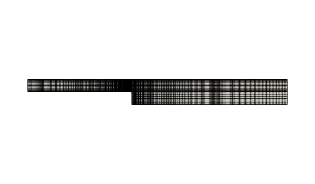
Fig.2 Mesh grading of 0.2
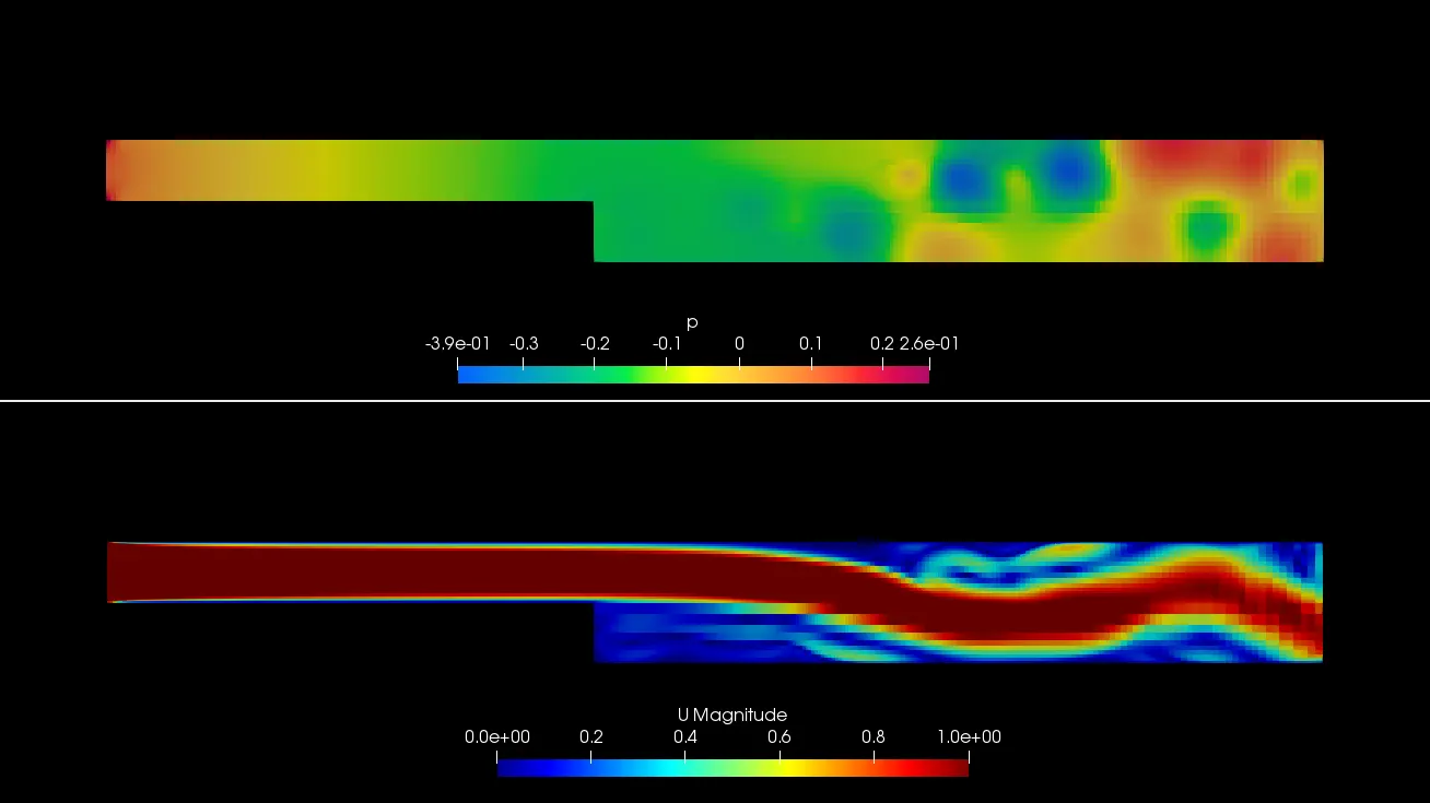
Fig.3 pressure and velocity contour of 0.2 grading
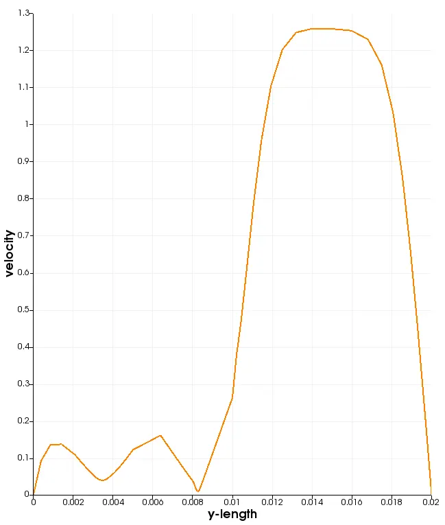
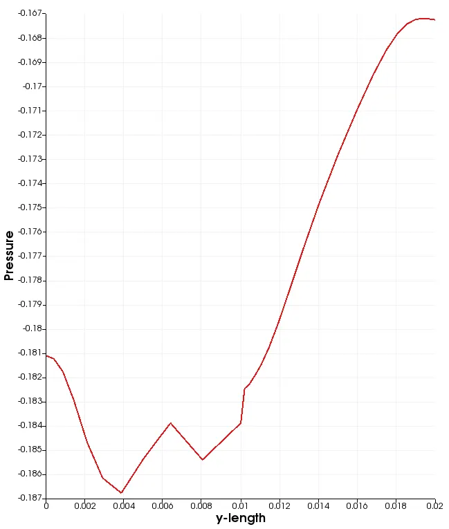
Fig.4 Velocity at 0.085m of 0.2 grading Fig.5 Pressure at 0.085m of 0.2 grading
0.5 grading:
    hex (0 1 2 3 11 12 13 14) (200 10 1) simpleGrading (0.5 2 1)
    hex (3 2 4 5 14 13 15 16) (200 10 1) simpleGrading (0.5 0.5 1)
    hex (2 7 6 4 13 18 17 15) (200 10 1) simpleGrading (2 0.5 1)
    hex (1 8 7 2 12 19 18 13) (200 10 1) simpleGrading (2 2 1)
    hex (10 9 8 1 21 20 19 12) (200 10 1) simpleGrading (2 2 1)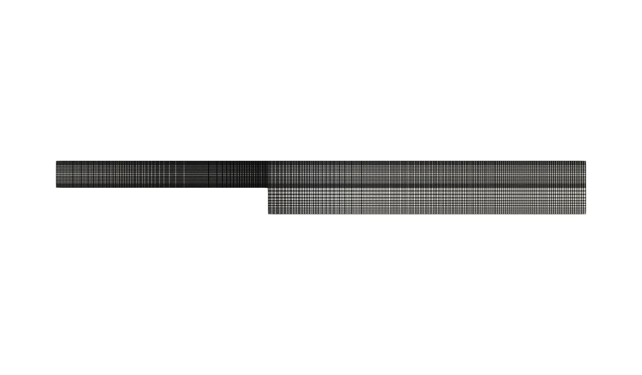
Fig.6 Mesh grading of 0.5
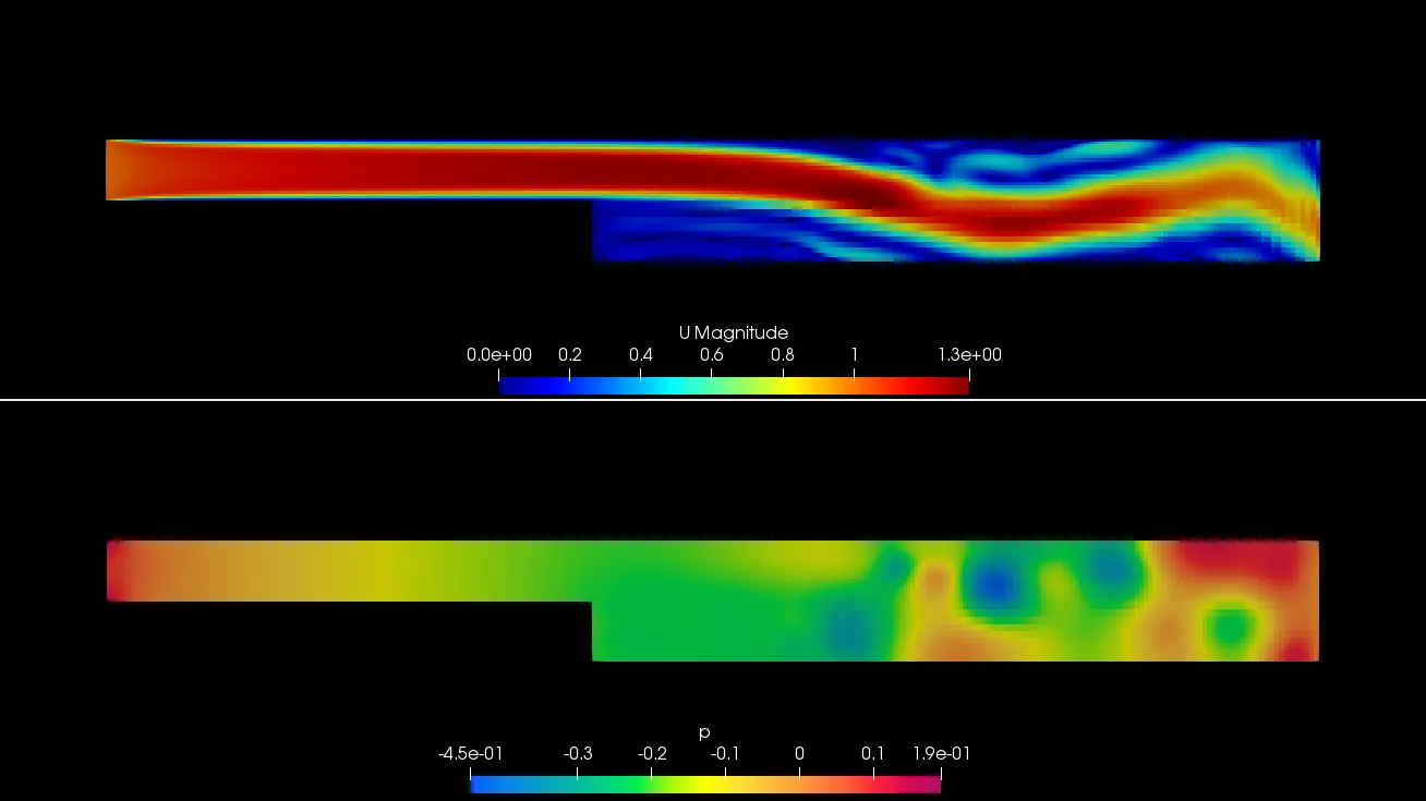
Fig.7 velocity and pressure contour of 0.5 grading
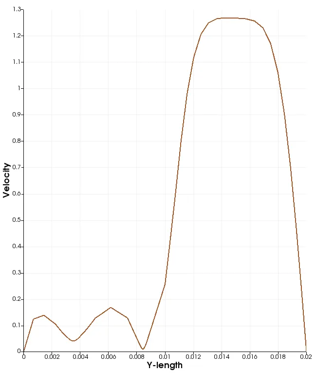
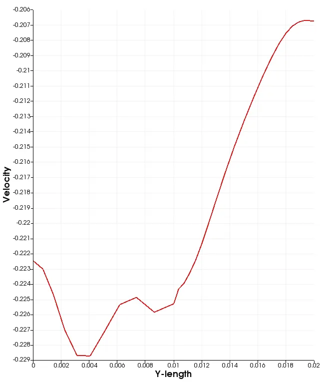
Fig.8 Velocity at 0.085m of 0.5 grading Fig.9 Pressure at 0.085m of 0.5 grading
0.8 grading:
    hex (0 1 2 3 11 12 13 14) (200 10 1) simpleGrading (0.8 1.25 1)
    hex (3 2 4 5 14 13 15 16) (200 10 1) simpleGrading (0.8 0.8 1)
    hex (2 7 6 4 13 18 17 15) (200 10 1) simpleGrading (1.25 0.8 1)
    hex (1 8 7 2 12 19 18 13) (200 10 1) simpleGrading (1.25 1.25 1)
    hex (10 9 8 1 21 20 19 12) (200 10 1) simpleGrading (1.25 1.25 1)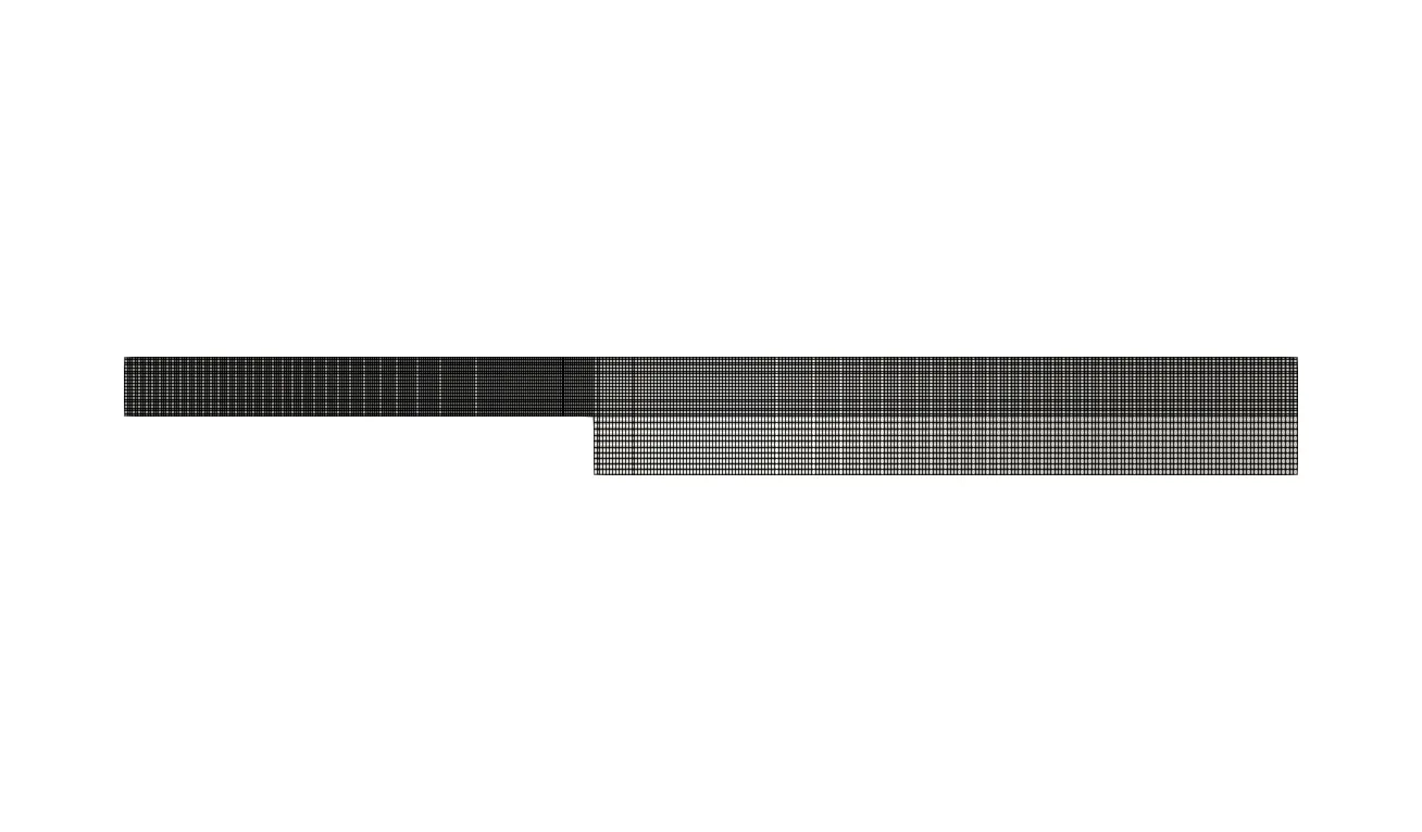
Fig.10 Mesh grading of 0.8
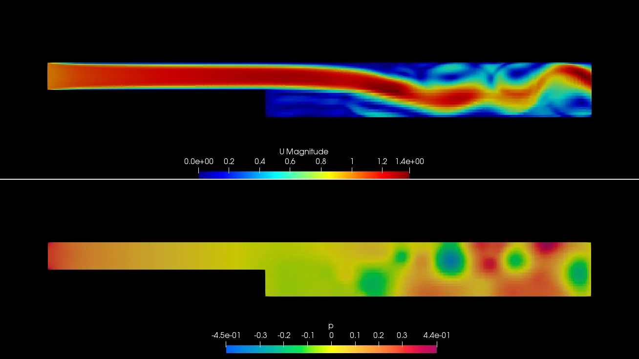
Fig.11 velocity and pressure contour of 0.8 grading
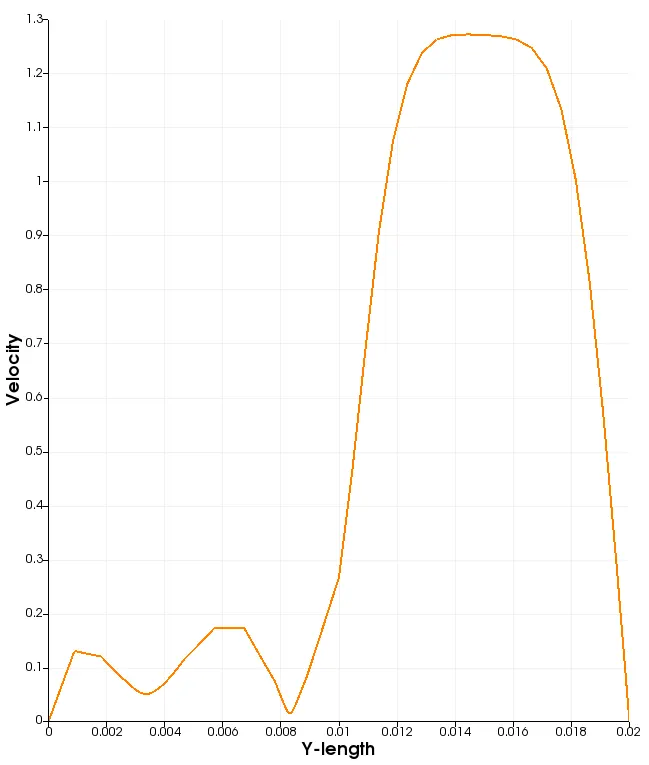
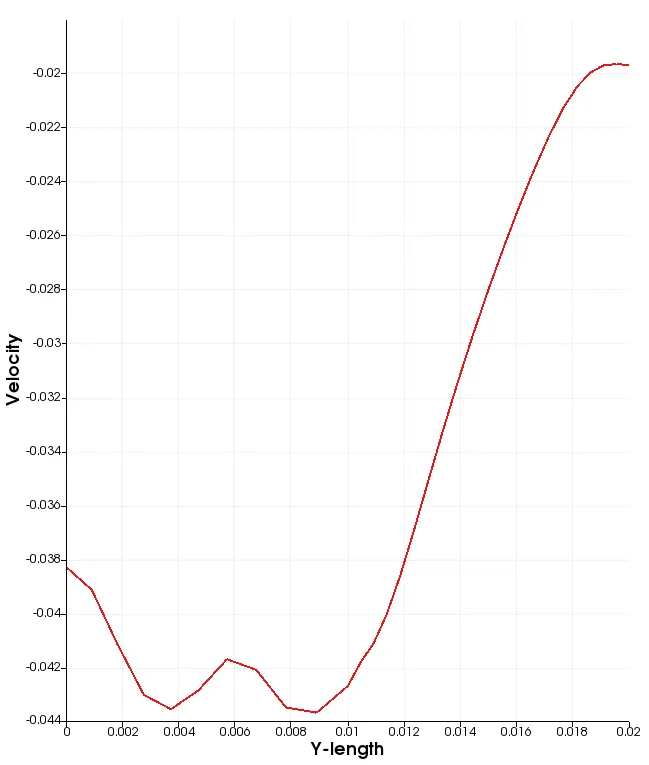
Fig.12 Velocity at 0.085m of 0.8 grading Fig.13 Pressure at 0.085m of 0.8 grading
1 grading:
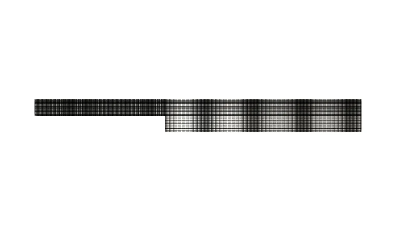
Fig.14 Mesh grading of 1
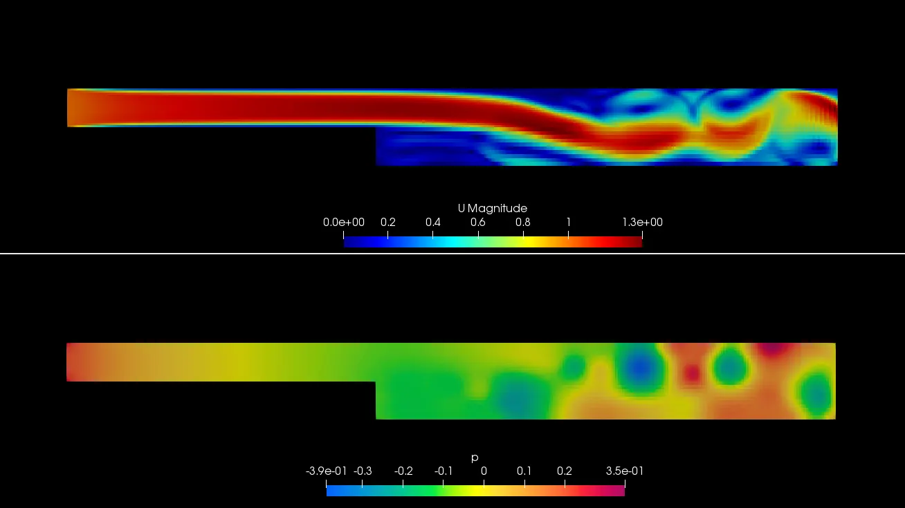
Fig.15 velocity and pressure contour of 1 grading
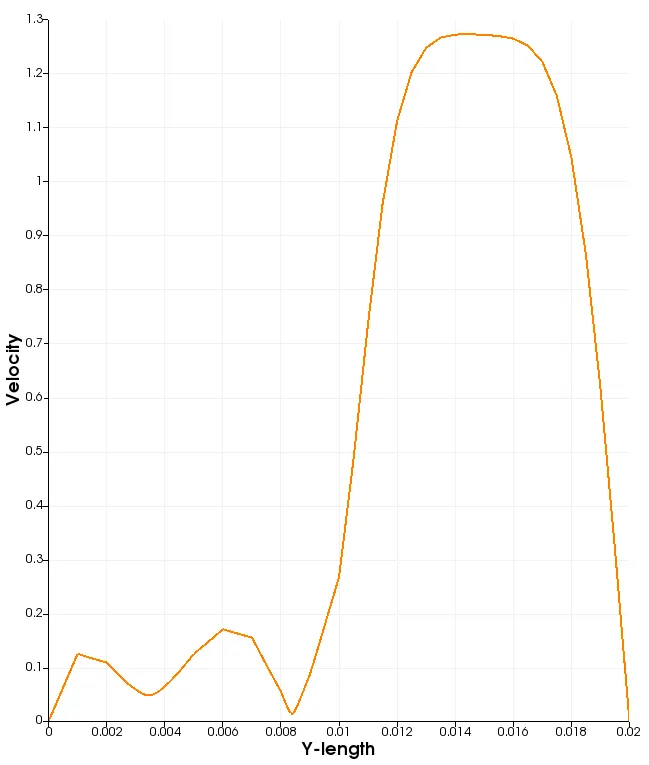
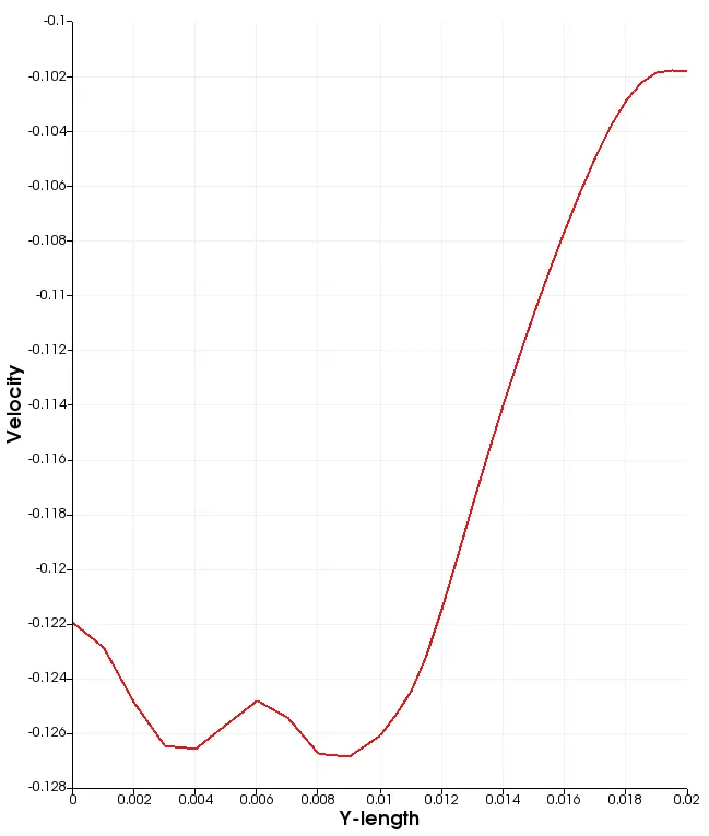
Fig.16 Velocity at 0.085m of 1 grading Fig.17 Pressure at 0.085m of 1 grading
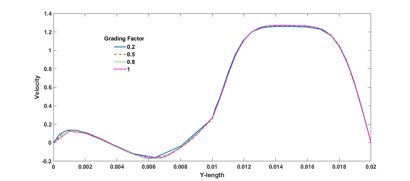
Fig.18 Velocity at 0.085m from inlet for gradings.
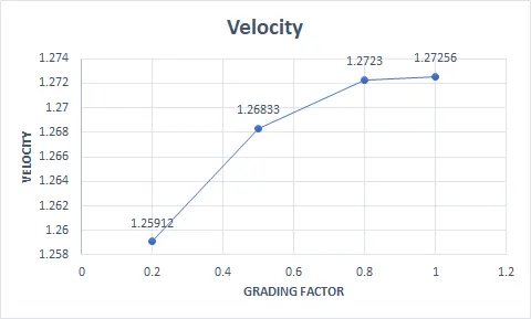
Fig.19 Velocity variation for grading factor.
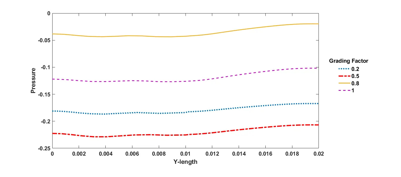
Fig.20 Pressure value at 0.085m from inlet for grading factors.
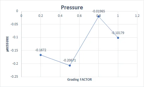
Fig. 21 Pressure variation for grading factors
Fig.22 Transient pressure and velocity contour of 0.2 grading. (t=3.5s)
Conclusion:
Flow variables are plotted for all the grading. There is not much of difference in the velocity profile, even though the value of maximum velocity decreases. But the pressure is not predictable. The main reason for trhis variation is because of boundary layer formation and mesh grading to accurately captue it. As the grading factor decreases from 1 to 0.2 the boundary layer capturing is most effective. As we can see in the mesh (fig 2,6,10,14) we refined near the step to capture the accurate solution. It also effect the variation in the soluton for different grading factor. From all above we can conclude that refining the mesh leads to numerical accurate solution.