Week 8-3D Tetra Meshing Challenge
MODULE 1
Create a Teramesh for Housing component with the following quality criteria.
TetraMesh Generation Method: 2D to 3D Conversion
Elements sizes: Min- 2 Units, Target- 5 Units, Max- 7 Units
Tet collapse: 0.150
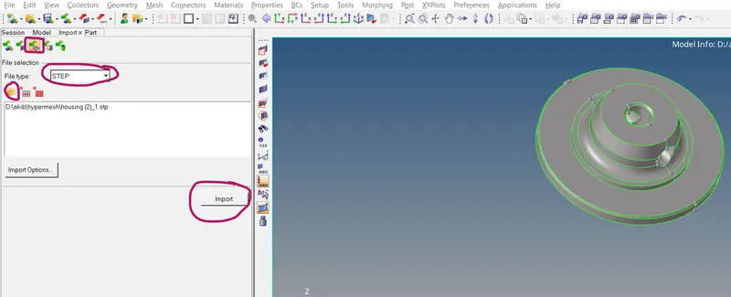
we have successfully imported the STEP file now we are going to check the model very carefully to fix the free edges if present and also we are going to remove unnecessary lines by using the toggle option or various other cleanup tools
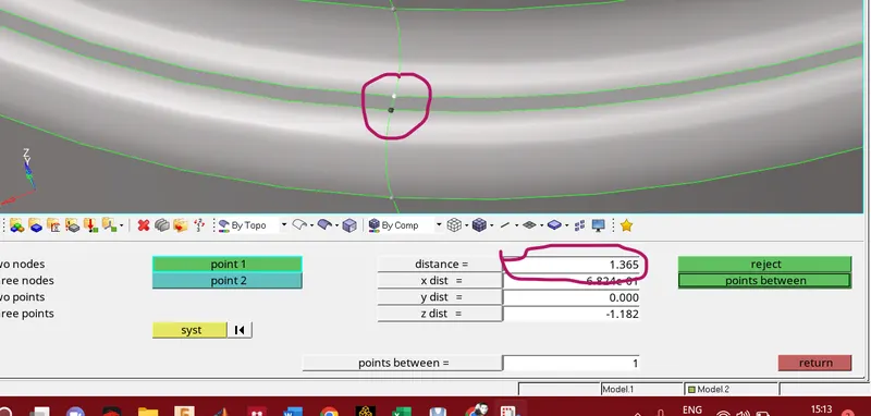
process to find out the element failure since the minimum element size is 2 thus below 2 units will fail the elements
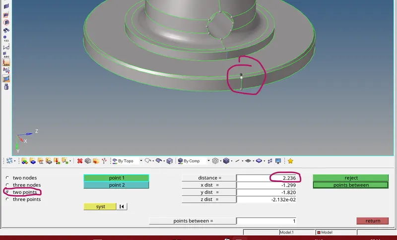
click on F4 >select 2 point option >select the point on the component to measure the distance
the distance we have measured is 2.23 and element failure will not occur in this region
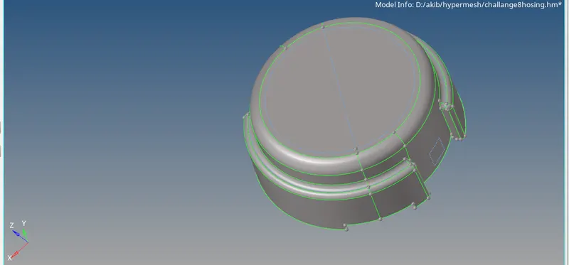
we have succesfully clean up the geometery and remove the unecessary lines from the model now we are going to generate surface mesh
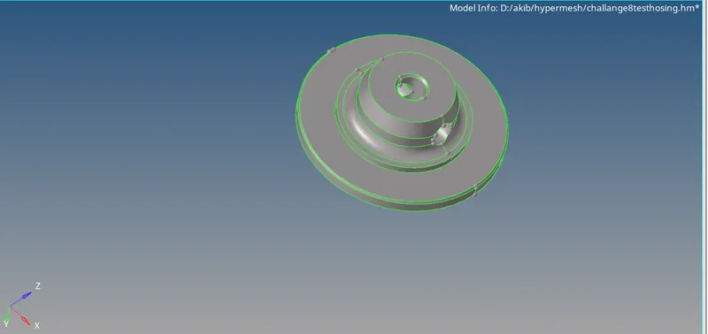
To set the quality criteria .click on preference >select criteria file editor>click on 2D
target element size =5 units
minimum element size=2
maximum element size=7
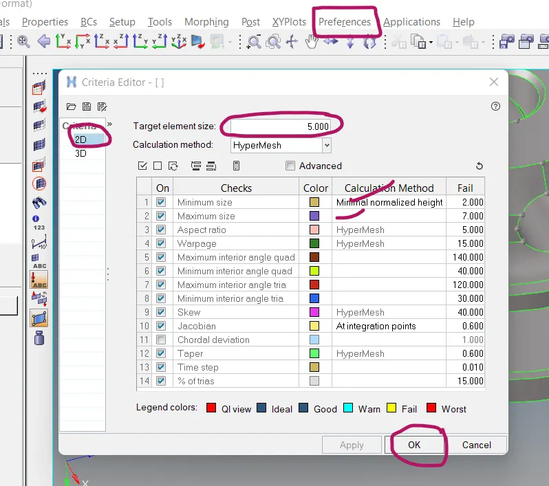
2D mesh generation process
click on 2D>select automesh

click on suface >select element size=5units>select mesh type trias>click on mesh
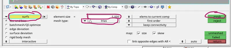
now 2D mesh has been generated
now we are going to check the quality of the elements
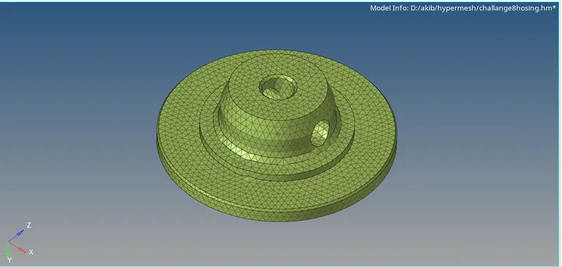
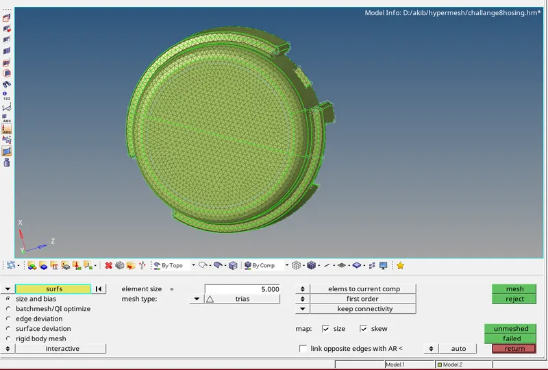
process to check element quality
click on F10
click on minimum length (2 units in our case )
there are almost 47 elments failed in the minimum length criteria
now we are going to fix these elements
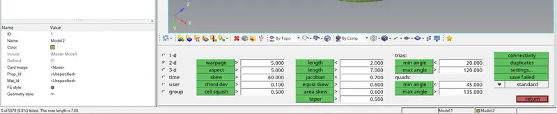
click on F4 (this will take us to the node edit pannel)
select the option 2 nodes
select the node of the failed element ,green node indicates fixed node where as the blue will move according to minimum and maximum lengthe that we can set in the distance box
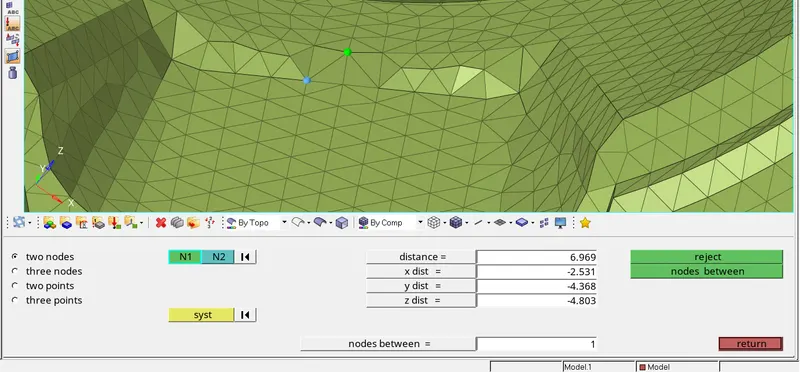
minimum and maximum element failure has been fixed and this can be seen from the image below
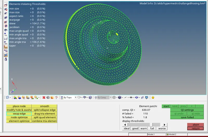
process to transform 2D mesh to 3D
click on 3D from the pannel >click on tetra mesh
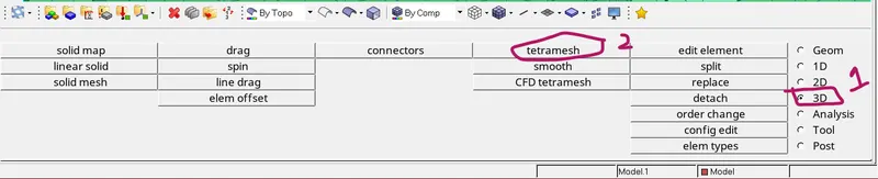
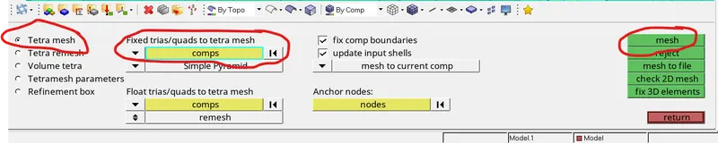
click on tetra mesh>select the component>click on mesh
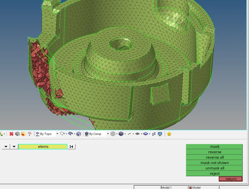
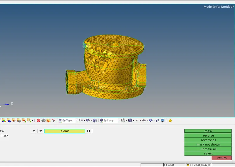
the 3D mesh has been generated in order to see the 3D elements click on mask option >select the elemens >select the mask
in order to check the element quality click on F10 >select 3D >select tet collapse(0.15)
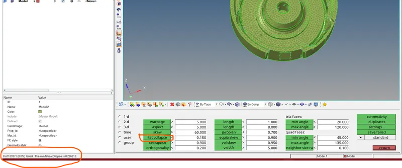
as we can see from the image 0 elements are failed from tet collapse
we have successfully generated the 2D mesh on housing and conversion of 2D mesh TO 3D tetra mesh.The mesh quality has been improved by using quality tools
MODULE 2
For the given model, Create a 3D Tetramesh with the following quality criteria.
TetraMesh Generation Method: Quick Tetra Mesh/ Volume Tetra Mesh
Target Element size: 3 Units.
Tet Collapse: 0.15
from the image below shows that the component is solid .
in order to view the geometric error we are going to delete the solids first
process to delete the solids
click on red cross icon > select the solids from panel> click on the solids and select displayed all>click on delet option
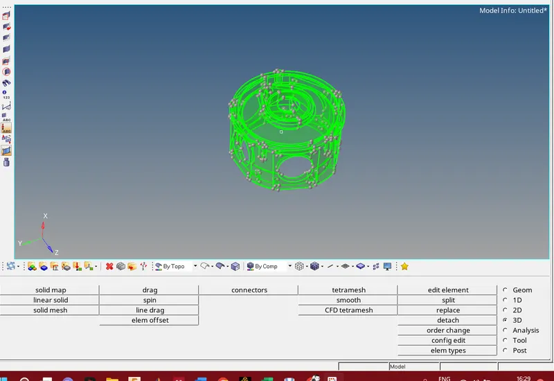
now the solids has been deleted from the component
now we are going to check free edges and we will remove free edges from the component
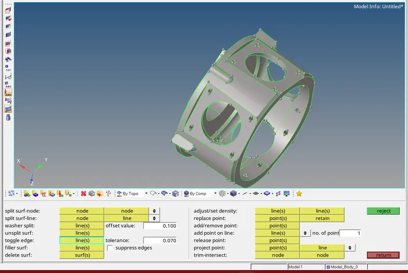
we have removed the unnecessary lines and also we have fix the free edge error
the next process is to do 3D meshing on the component
click on 3D from the pannel>click on tetra mesh

select the volume tetra >select the surface >set the element size >click on mesh
due to some geometric error the mesh has not been generated and shows a message that surface is not enclosed
we have use the other method that will automatically cleanup the geometry and do meshing on the component
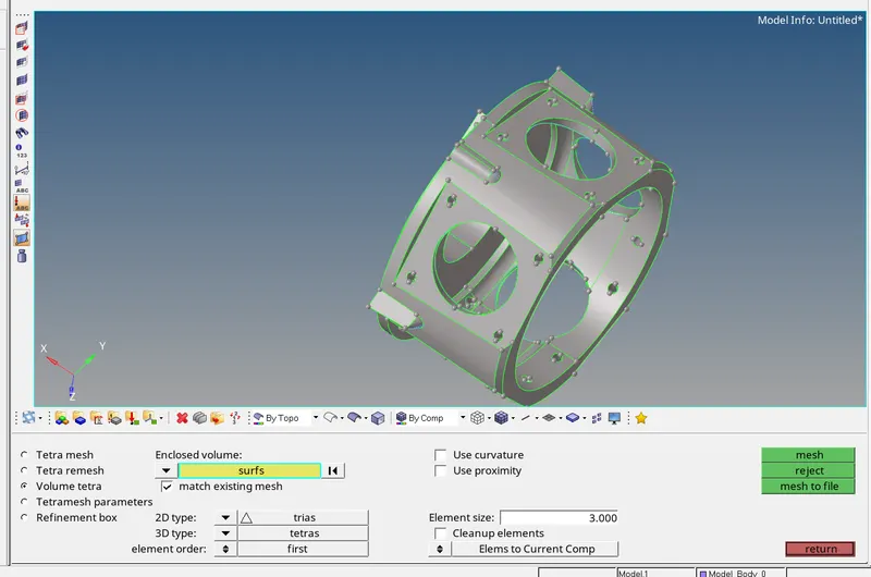
Method 2
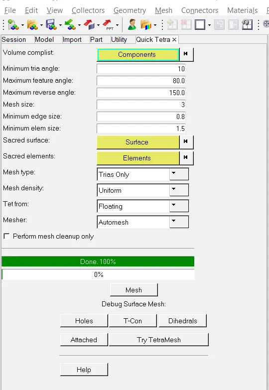
click on view from the main menu>click on utility>select quick tetra mesh>select the component
set min element size=1.5 units
mesh type =trias only
now click on mesh and mesh will generated automatically from 2D to 3D as shown in the image below
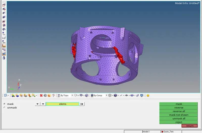
in order to view the 3D mesh click on mask and select some part from the component
mask these elements from the component
MODULE 3#
For the given assembly model, Create a 3D Tetramesh with the following quality criteria.
TetraMesh Generation Method: Quick Tetra Mesh/ Volume Tetra Mesh
Target Element size: 4 Units.
Tet Collapse: 0.15
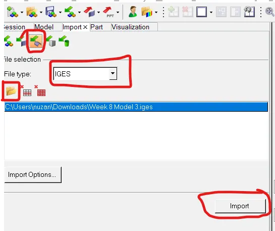
process to import IGES file
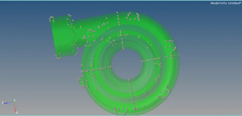
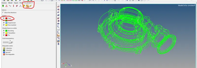
From the image below there are no free edges
to check free edges
click on wire frame mode
select the visulization tab
untick shared ,suppresed and non mainfold
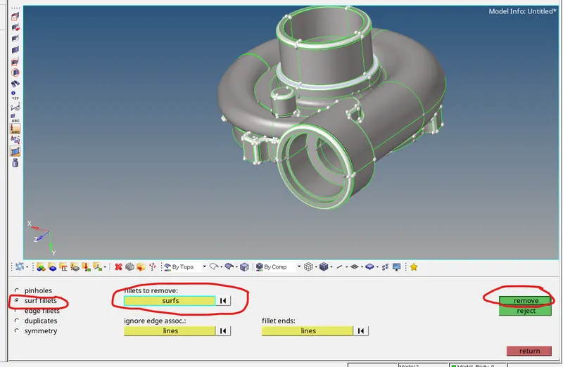
surface fillets
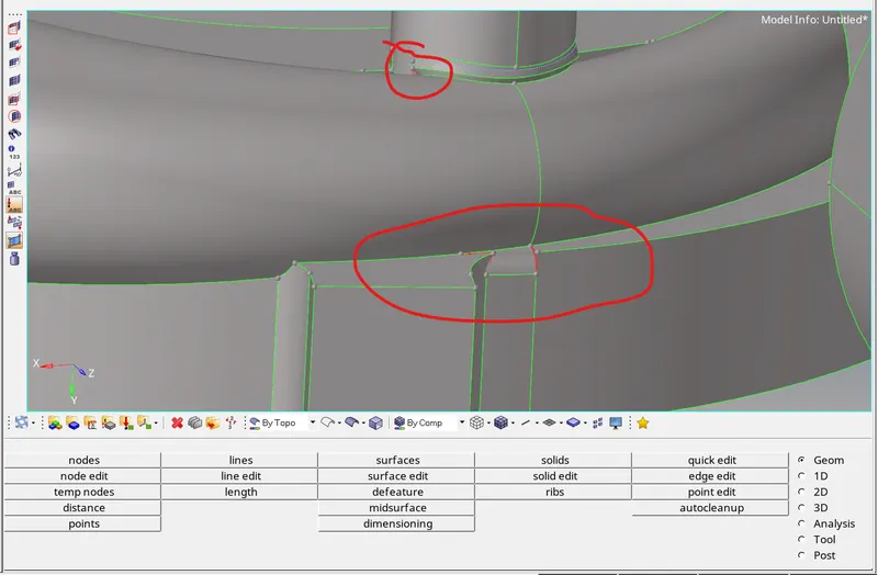
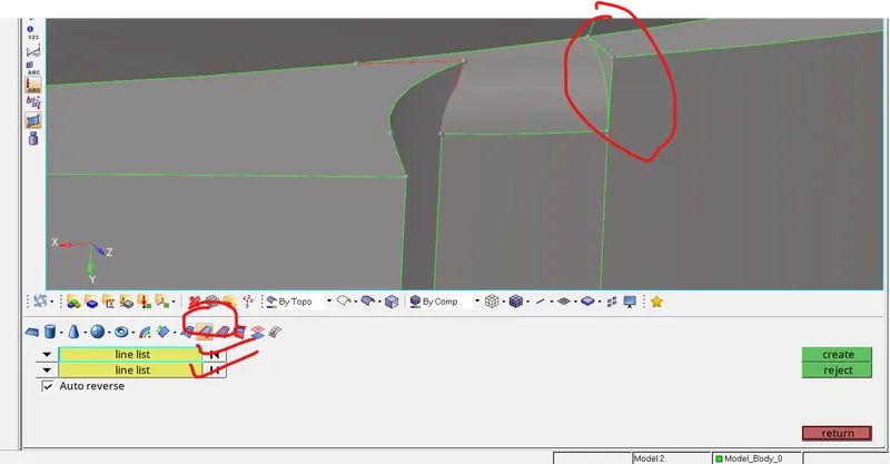
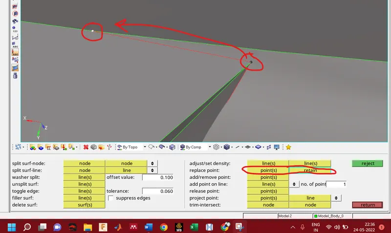
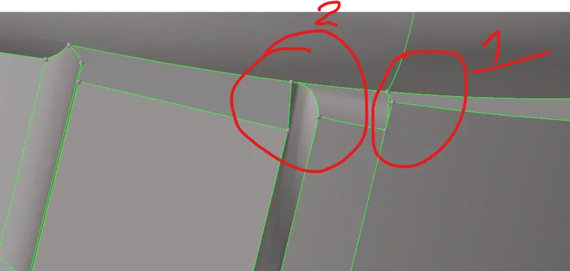
we can do meshing same as in the above cases
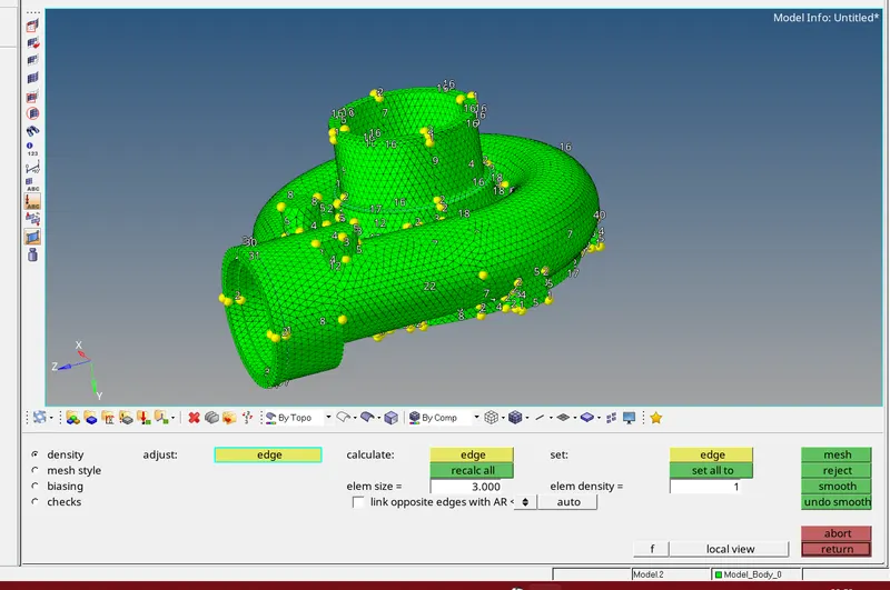
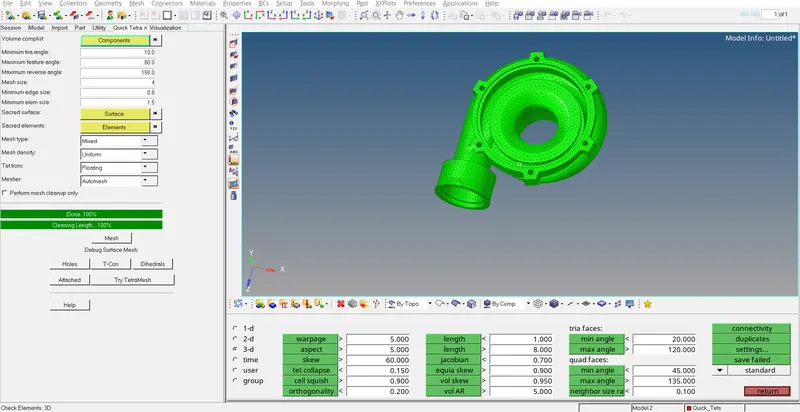
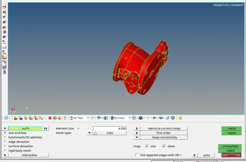
component contains solid
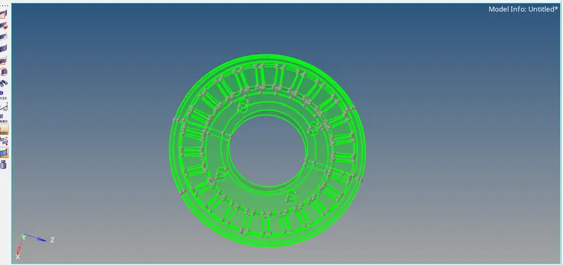
2D meshing of the component
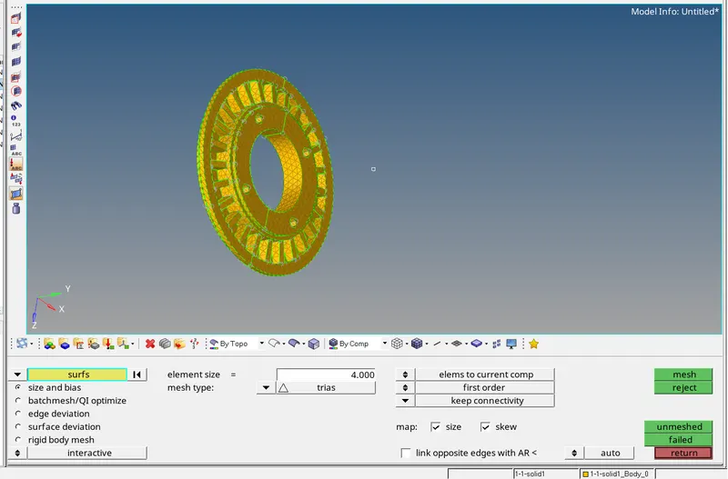
conversion of 2D mesh to 3D
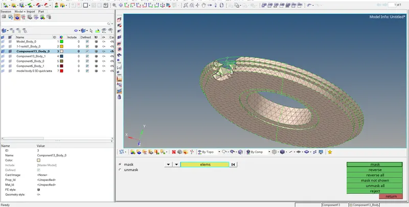
the below component is same as above
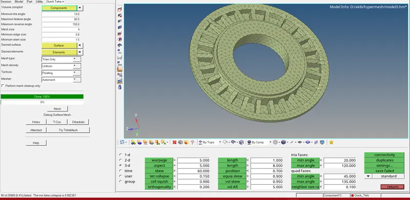
we have mask some portion of the component to see the 3D tetrahedral elements
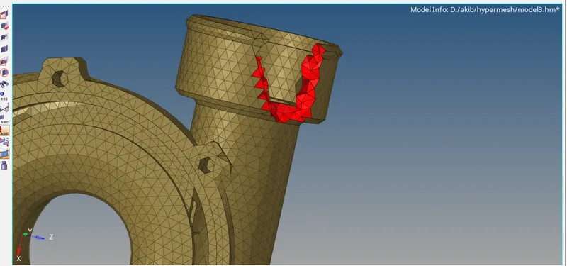
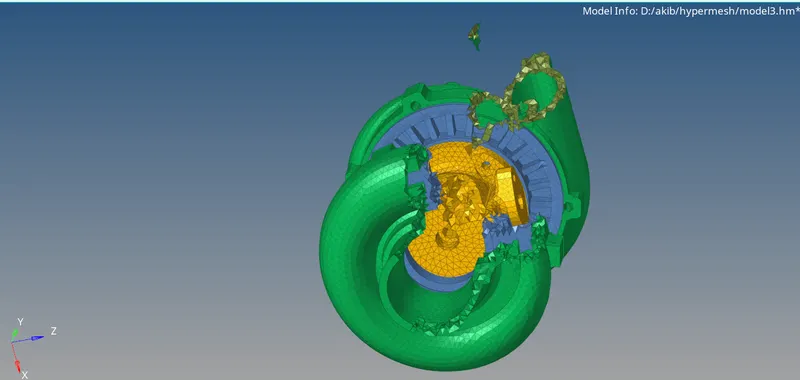
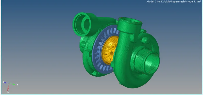
this is the final model of assembely we have succesfully generated 3D mesh to below component and the file has been attached of this model below
conclusion
in the above modules /components we have learn 3D tetra meshing and the conversion of 2D mesh to 3D mesh
we have learn how to fix the tet collapse and other quality parameters
we have learn different methods of tetra meshing