Week 8-3D Tetra Meshing Challenge
3D Tetra Meshing
OBJECTIVE:-
1) To create a Teramesh for Housing component with the following quality criteria.
TetraMesh Generation Method: 2D to 3D Conversion
Elements sizes: Min- 2 Units, Target- 5 Units, Max- 7 Units
Tet collapse: 0.15
2) For the given model, create a 3D Tetramesh with the following quality criteria.
TetraMesh Generation Method: Quick Tetra Mesh/ Volume Tetra Mesh
Target Element size: 3 Units.
Tet Collapse: 0.15
3) For the given assembly model, Create a 3D Tetramesh with the following quality criteria.
TetraMesh Generation Method: Quick Tetra Mesh/ Volume Tetra Mesh
Target Element size: 4 Units.
Tet Collapse: 0.15
PROCEDURE:-
Objective - 1
Import .stp file - First of all import the .stp file because the given model is in .STP format hence we need to import using File > Import > Geometry > STEP > Import. The Procedure can be seen in below image.
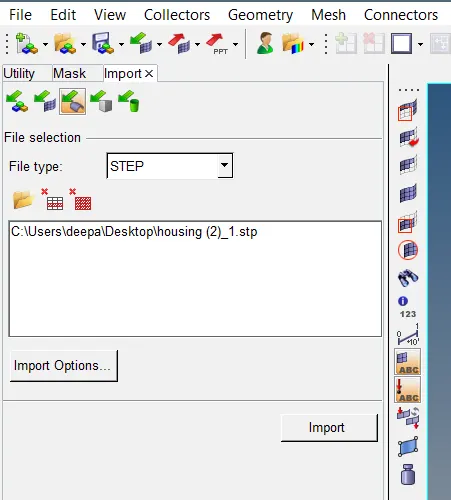
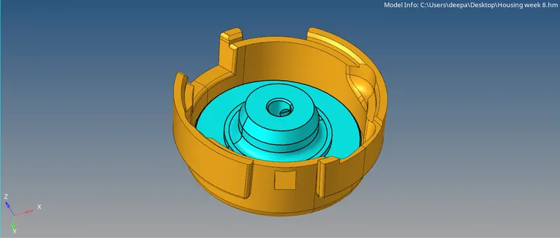
Fig: Importing Model
Delete solids - Now change the geometry in By Topo mode to see the solids and then delete all the solids contained by the model and for that, go to Tool > delete > solids > Select the model > delete.
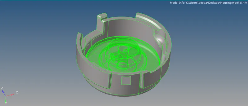
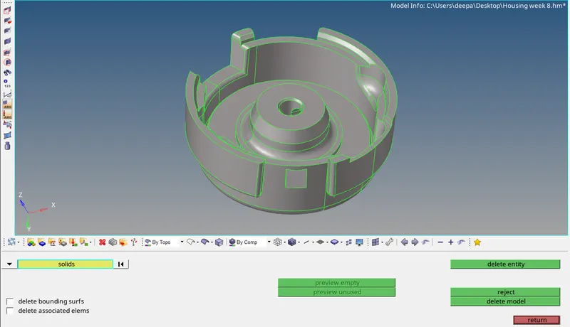
Fig: Solids Deleted
Geometry cleanup - View the model in wireframe mode in order to check that if there is any red con present because having red con confirms the fact that there is something wrong with the model geometry it can be either free edges or something else which is not acceptable and need to get addressed. No issue was found in this case here but we need to fix the issue if found any and everything looks proper.
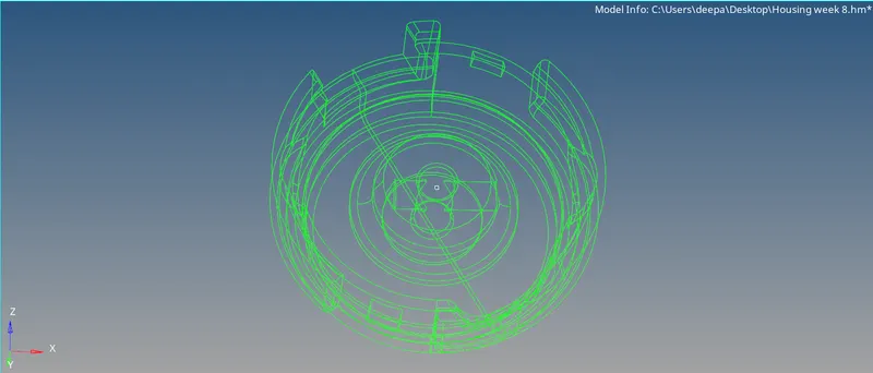
Fig: Wireframe Mode
Defeaturing - Defeaturing needs to be done wherever required so we will remove the lines where minimum thickness error may occur so we remove the lines having length less than that of the min. element length. We can do it manually or by using autocleanup tool.
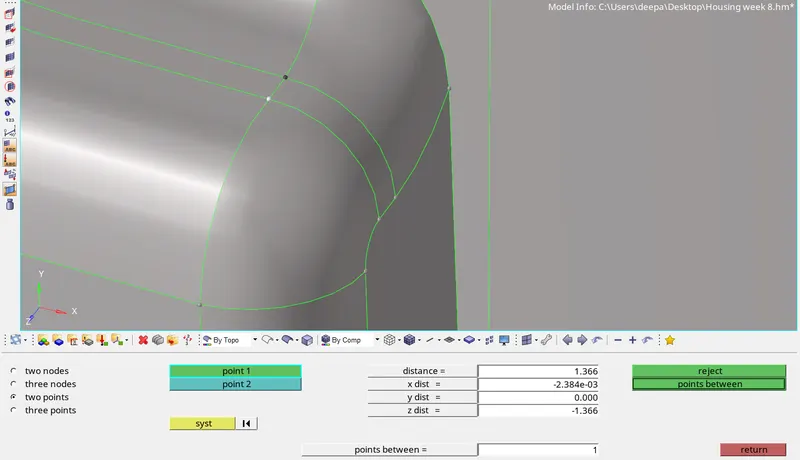
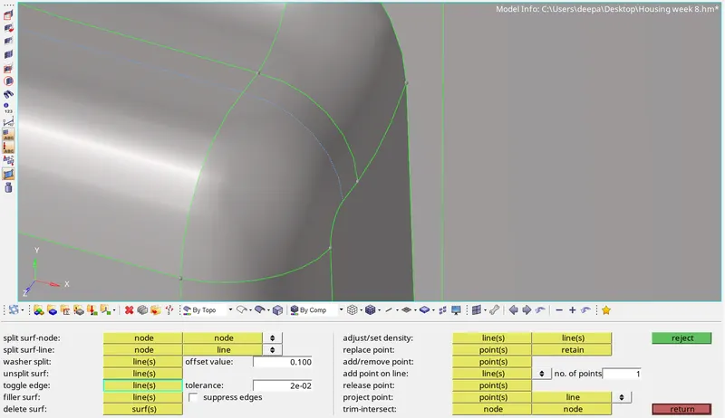
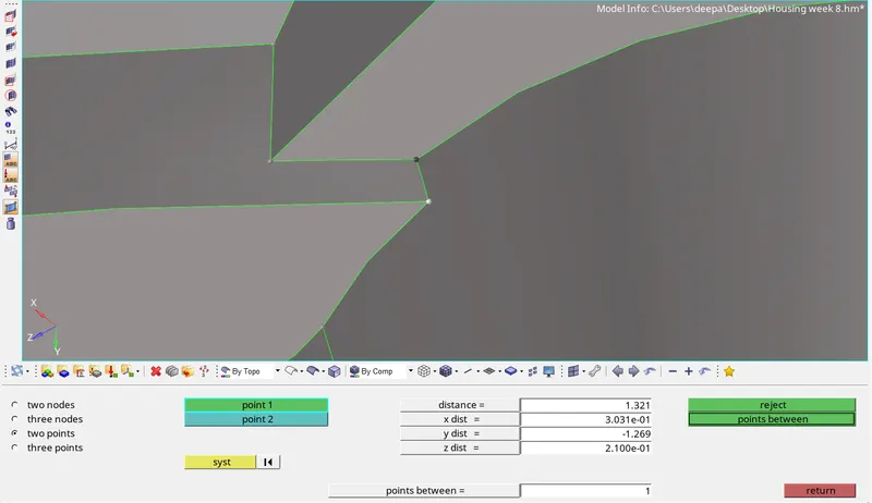
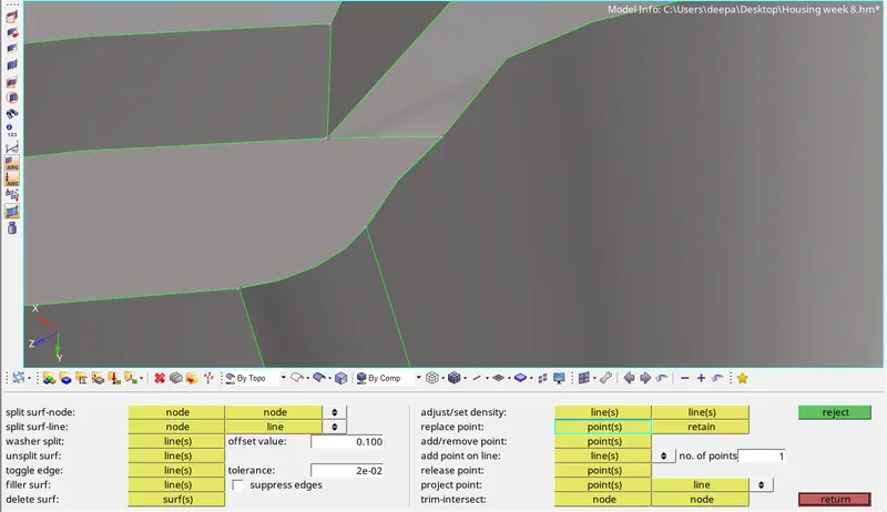
Fig: Defeaturing
Asssign quality criteria - Since the model has to be meshed as per the quality criteria so now we have to assign quality criteria for 2D meshing.
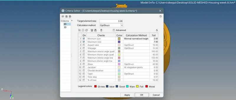
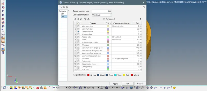
Fig: Quality Criteria
2D meshing - Once the quality criteria is set we can proceed with meshing and to do that, we will go to 2D > automesh > surf.

Fig: Automesh Panel
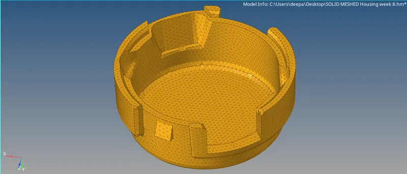
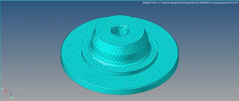
Fig: Surface/2D Meshed Model
The mesh initally gives many off elements, most of which can be removed by smoothing the mesh however, at few areas maximum element length failures can be resolved by Remesh. Minimum length errors on few regions could be fixed by moving the nodes. After resolving failed elements, the mesh looks like the image given below.
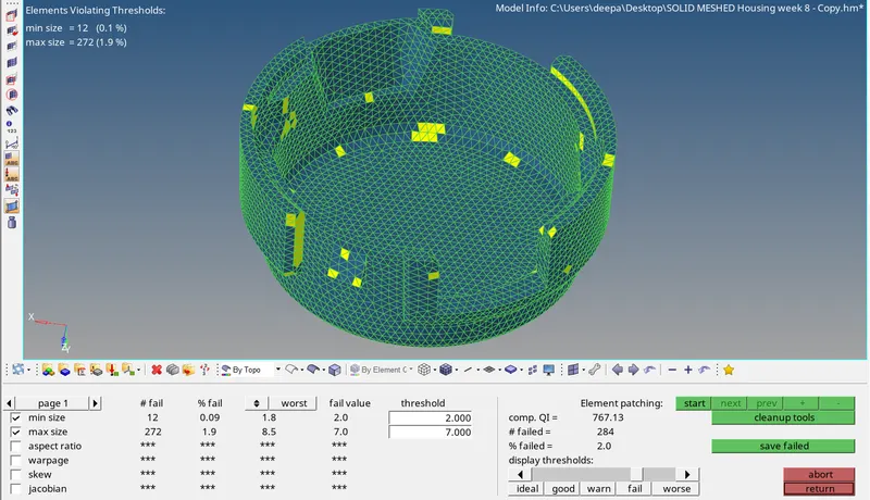
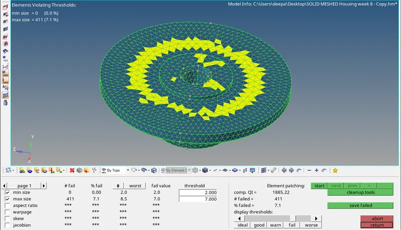
Fig: Failing Elements
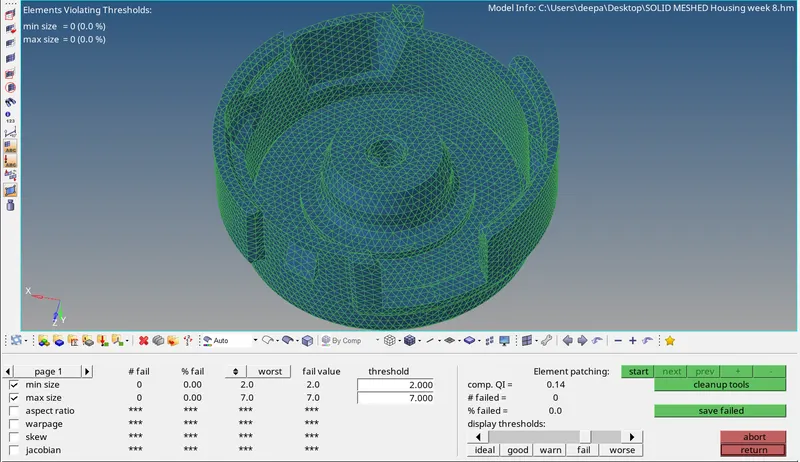
Fig: No Failed Elements
3D meshing - Now it is time to convert this 2D mesh into volume or 3D mesh and for this, go to 3D > tetramesh > Tetra mesh > elems > mesh. This will create 3D volume mesh for given model as can be seen in image.

Fig: Tetra Mesh Panel
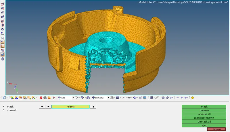
Fig: Tetra Meshed Model
Once Tetra Mesh is created we will check for quality issues. In the given model Tet Collapse is the most important failing criteria, hence we will check it by going to Tool > check elems > 3-d > tet collapse and failed elements are resolved by either remeshing those elements with the required tet collapse criteria or adjusting manually by translating the element's node until it satisfies the quality criteria.
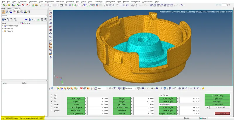
Fig: Tet Collapse Cleared
Objective - 2
Import .iges file - import the .stp file because the given model is in .IGES format hence we need to import using File > Import > Geometry > IGES > Import.
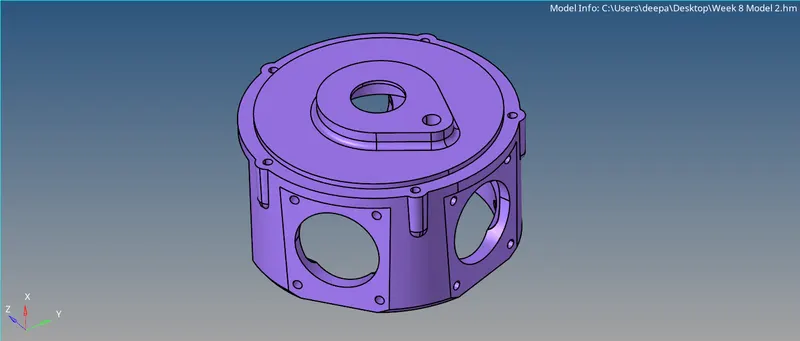
Fig: Model Import
Delete solids - Now delete the solid part if found any.
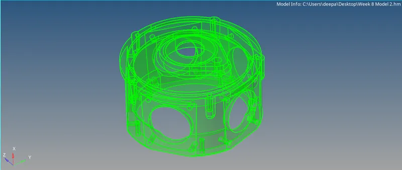
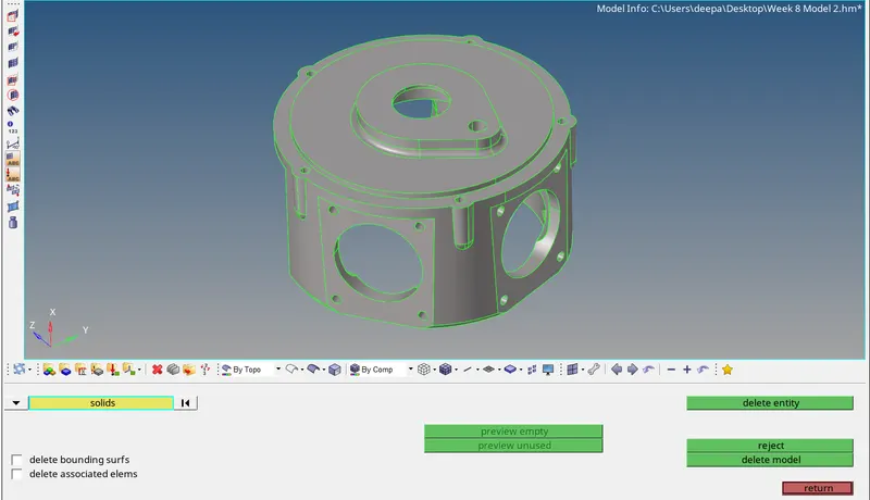
Fig: Solid Deleted
Geometry cleanup - Now for geometry cleanup, view the model in wireframe mode and fix if any issue found. After that, for automatic geometry cleanup go to Geom > autocleanup > surfs > autocleanup.
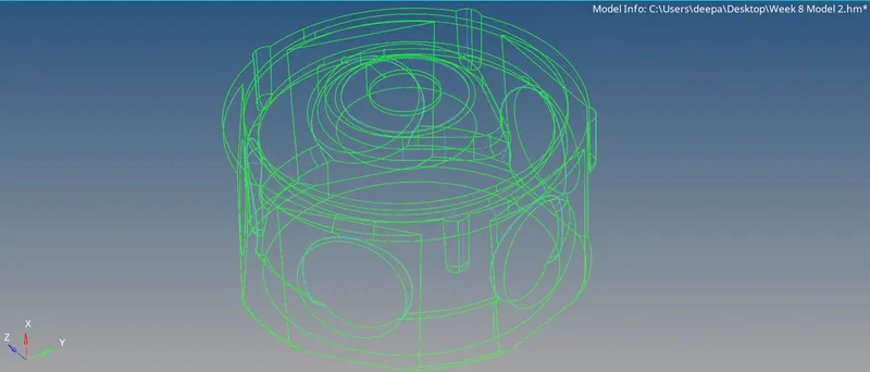
Fig: Wireframe Mode
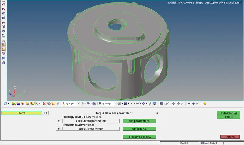
Fig: Model After Autocleanup
Quality criteria setup - Setup quality criteria for the model before meshing. Go to Preferences > Criteria File Settings > Setup criteria values > Apply > OK.
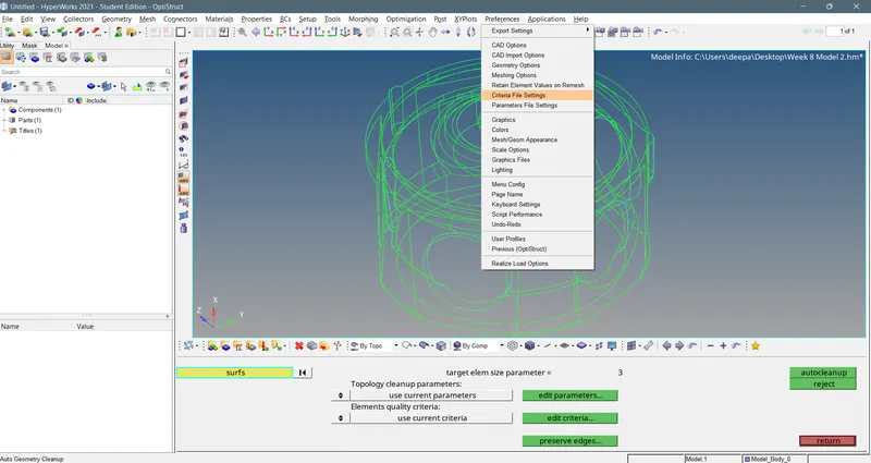
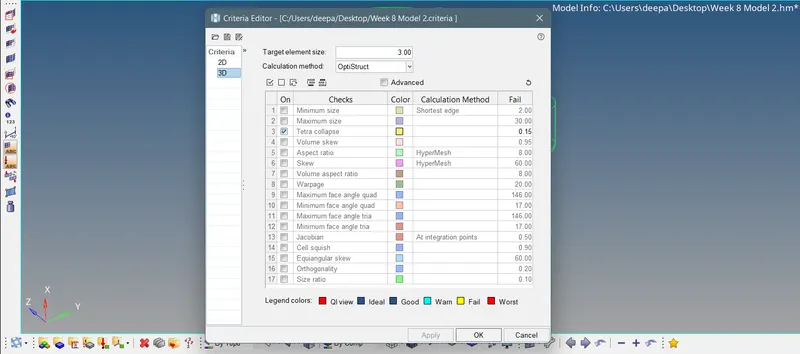
Fig: Quality Criteria Setup
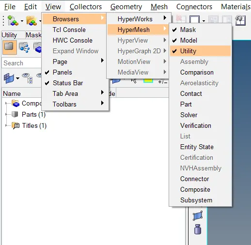
Quick Tetra Mesh - For performing tetra mesh, Go to View > Browsers > HyperMesh > Utility > Geom/Mesh > Quick TetraMesh > Select component, give mesh size and mesh type > Mesh.
For component selection, click on the component and then click on proceed.
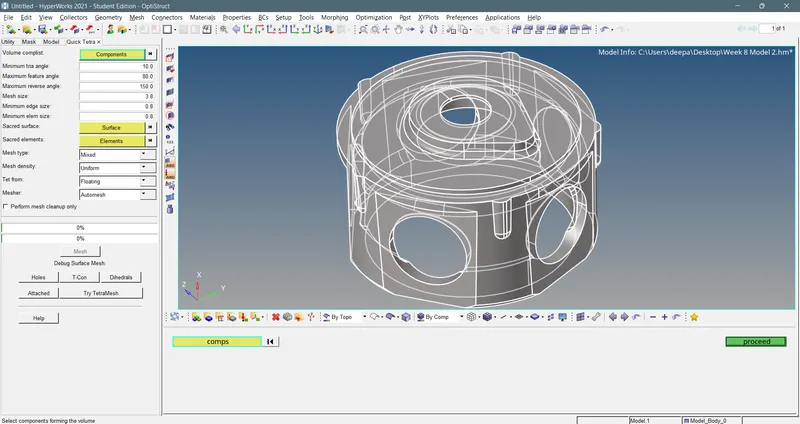
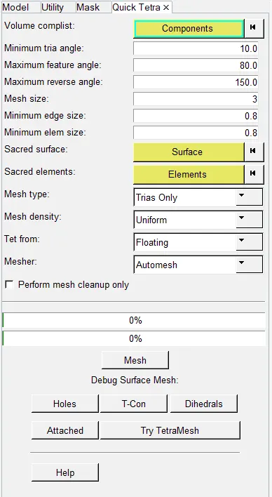
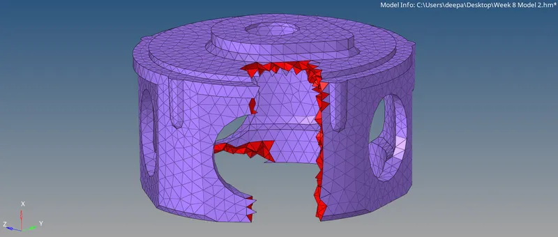
Fig: Quick Tetra Meshed Model
Mesh cleanup - After meshing when we check for tet collapse failures. Go to Tool > check elems > tet collapse, we found 72 elements violating quality criteria.
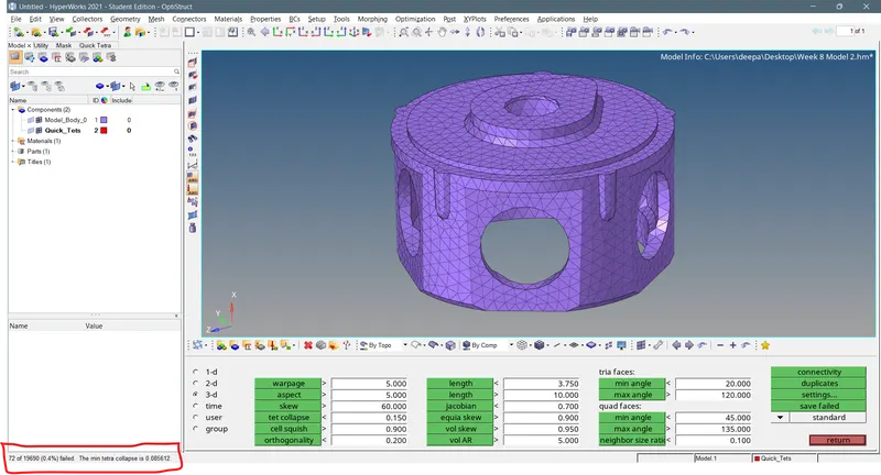
Fig: Tet Collapse Failed Elements
So we go to 3D > tetramesh > Tetramesh parameters and enter values as shown below.

Fig: Tetramesh parameters Panel
Now Go to Tetra remesh > elems > remesh to get rid of the failing elements.

Fig: Tetra Remesh Panel
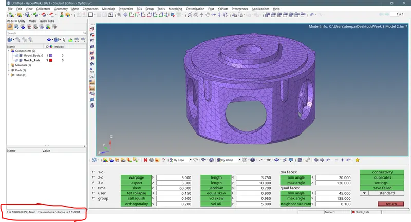
Fig: Tet Collapse Resolved
Objective - 3
- Import the .iges file to the physical screen of the software.
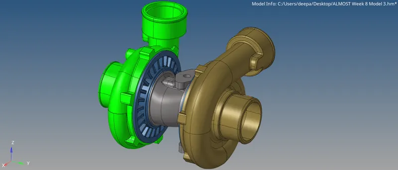
Fig: Model Import
The model includes 5 individual assembly parts as shown below so each of the component would be meshed individually.
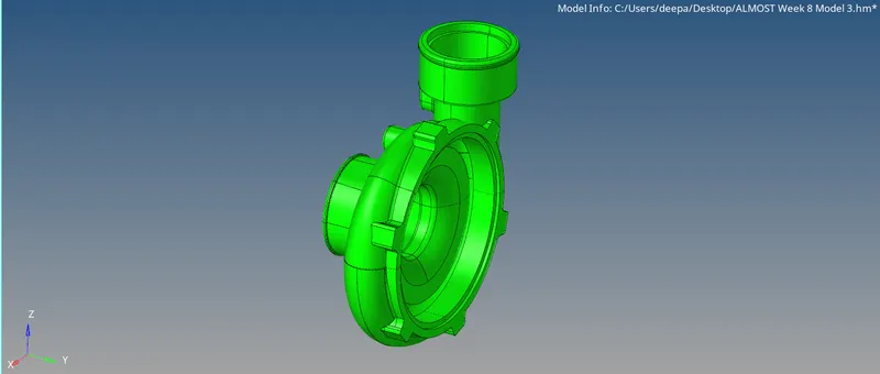
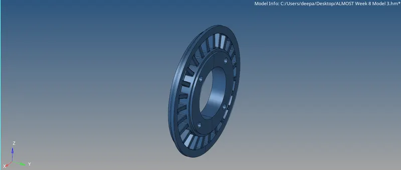
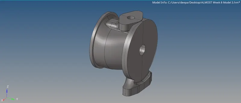
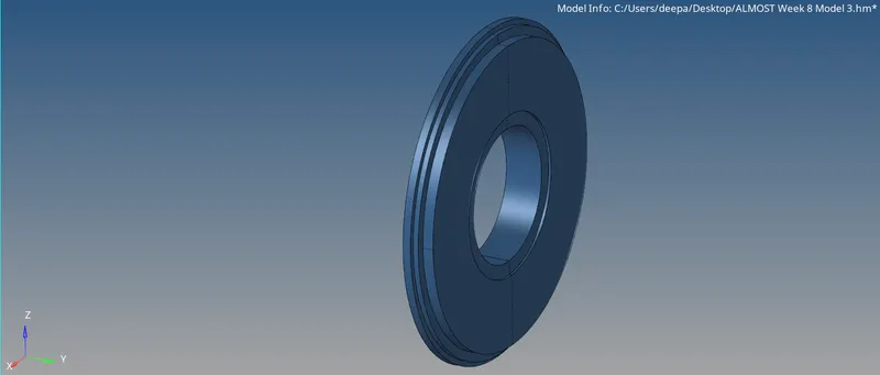
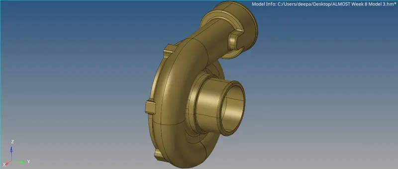
Fig: Part - 1 to Part - 5
- Once the model is imported we will view the model in wireframe view to check if any issue is found. The model did not have any geometerical issue. The below image shows the same.
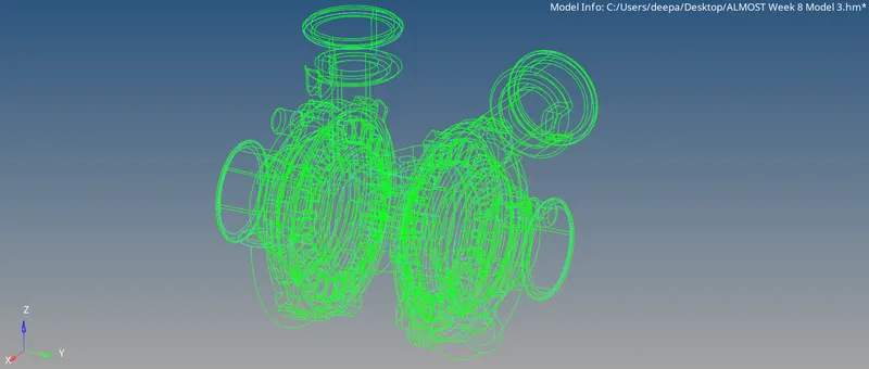
Fig: Model in Wireframe mode
- For geometry cleanup go to Geom > autocleanup > surfs > autocleanup and perform geometry cleanup for each of the part individually.
- Hiding all the components except for one at a time, either quick tetra mesh or volume mesh from the 3D tab is performed on the components. Quality criteria should be setup according to specified criteria before heading towards meshing. Meshig of part 3 is performed with quick tetra mesh and meshing for all the other parts is performed with Volume tetra option in 3D panel so for volume tetra, go to 3D > tetramesh > Volume tetra > Enter element size > surfs > mesh. Try different meshing methods to check which one is the most suitable. We can also go with the standard procedure described with "model 1" if these two methods don't work as per our desire.
- Tet collapse for the 3d elements is checked and failed elements are resolved by either remeshing those elements with the required tet collapse criteria or adjusting manually by translating the element's node until it satisfies the requirements.
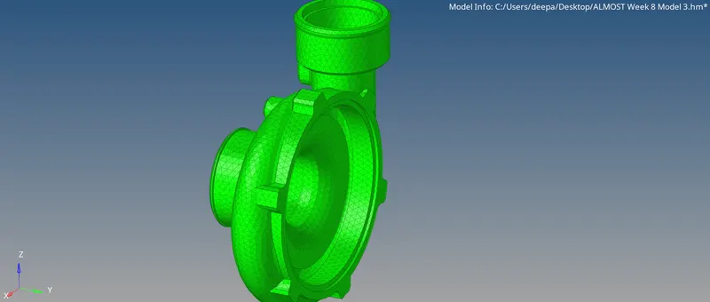
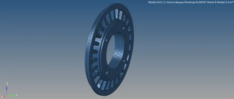
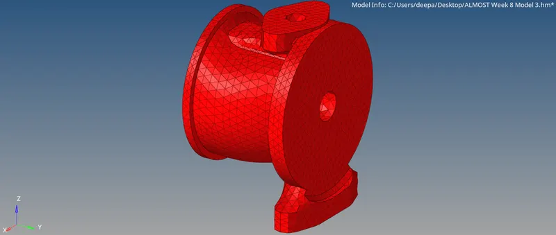
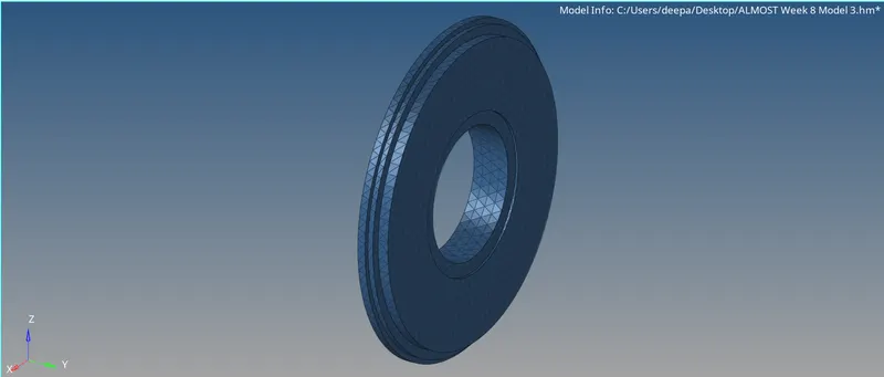
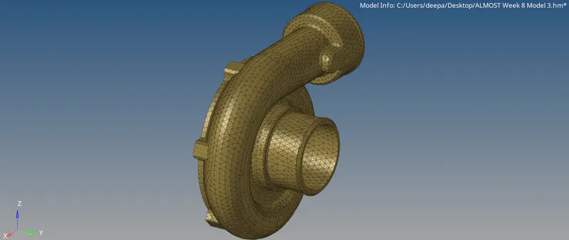
Fig: Individually Meshed Parts
Final 3D Meshed Model -
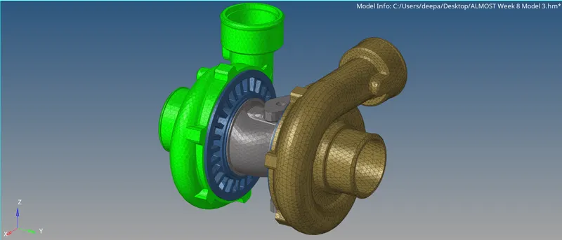
Fig: Final 3D Meshed Model
RESULT:-
Successfully performed surface tria and volume/3D meshing for given models and learned about tet collapse failure and the solution.