Week 8-3D Tetra Meshing Challenge
MODEL 1 :
OBJECTIVE : To generate a tetramesh for a housing component wih the given quality criteria.
Procedure:
step 1: Import the component and select F to fit the component in the GUI area
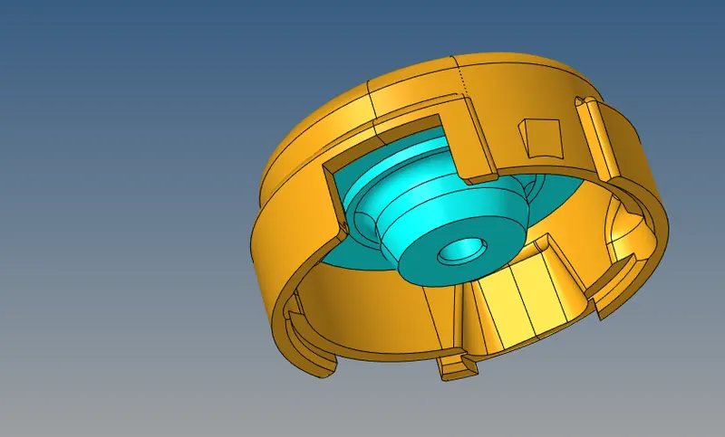
Step 2 : As the method to be followed is 2D to 3D conversion .
Delete the solid surface by the delete command so that we can work on the surface.
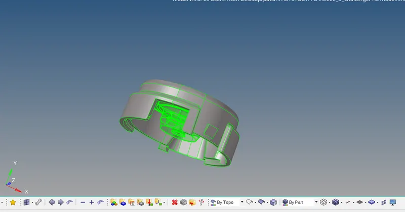
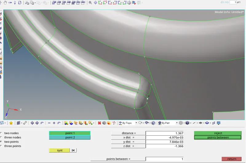
Step 3: As the minimum element size is 2 units , make the necessary repair wherever there is a possible element failure with respect to minimum element by command F2 to check the distance and F11 for toggle .
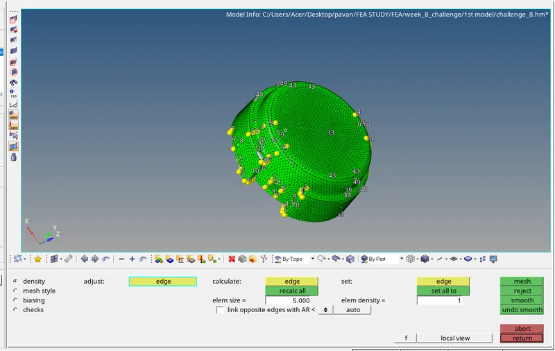
Step 4: Now perform the 2D mesh using the criteria of minimum size : 2 , max : 7 units and Target of 5 units by selecting only trias as the element type.
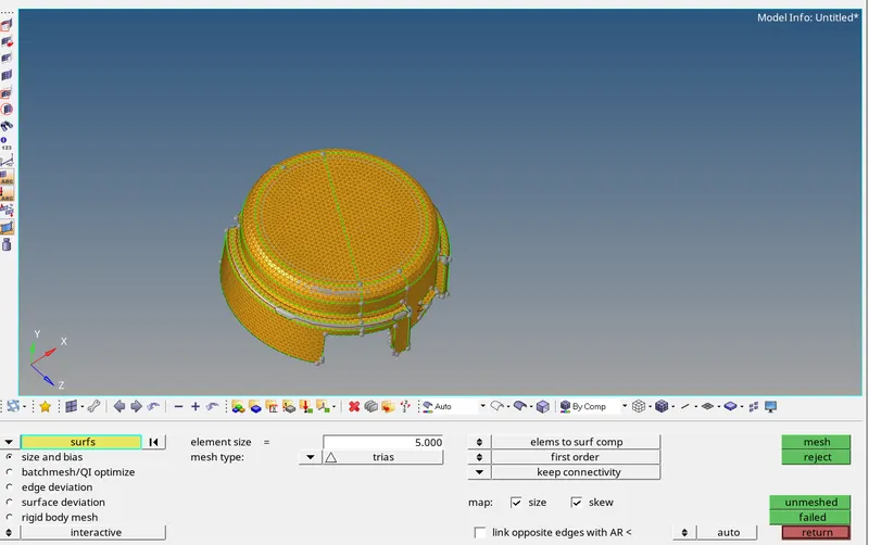
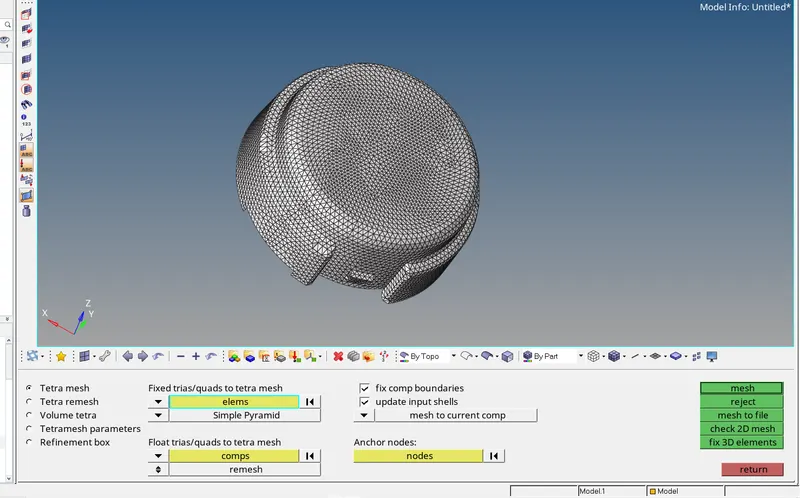
Step 5: Now convert the 2d to 3D elements by using the command 3D--> Tetramesh .
and select the tria elements and mesh .
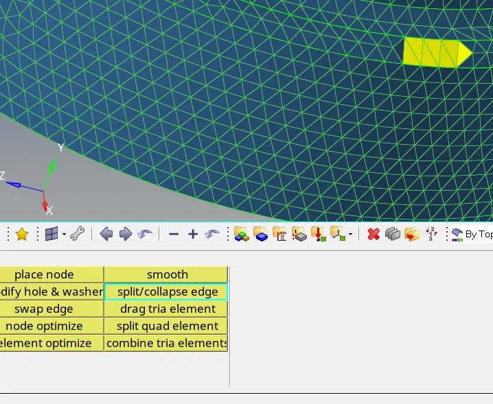
Step 6: the elements are repaired using the quality command . the tools like split/collapse edge tools are used.
Step 7: After the repair, check for Tet collapse and the elements are repaired until they are in acceptable range .
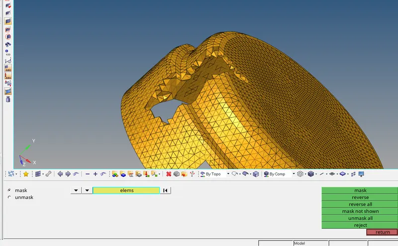
Step 8 : perform the similar operations for the 2nd part of the same housing component to obtain the 3d tetramesh from the 2D elements.
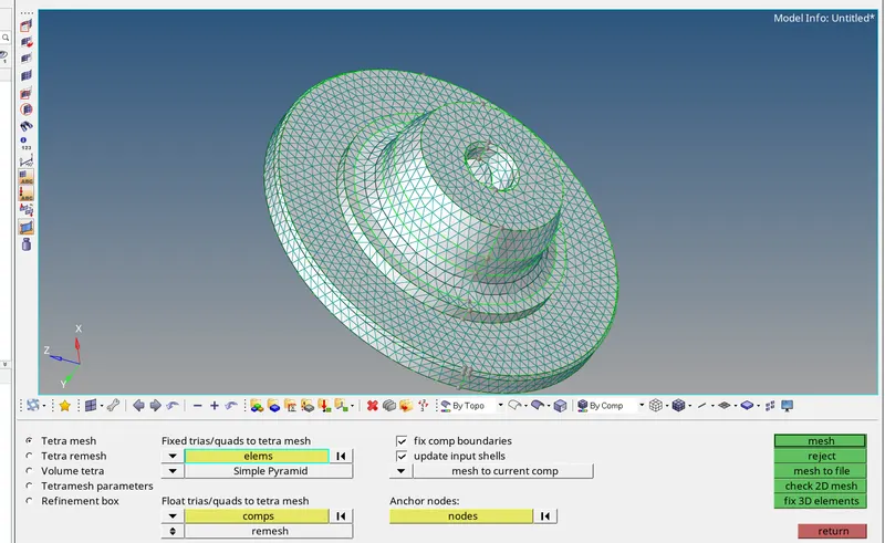
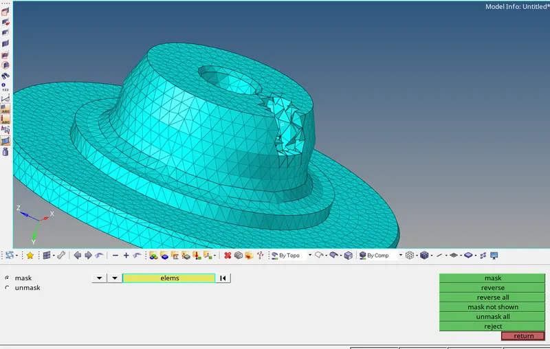
Step 9 : the tet collapse is also checked for this part.
conclusion : It is learned that the component can be tetramesh geneerated by using the method of 2D to 3D elements conversion.
MODEL 2:
OBJECTIVE : Generate the 3D mesh using the Quick /Volume tetra mesh.
Procedure:
step 1: Import the component and select F to fit the component in GUI area .
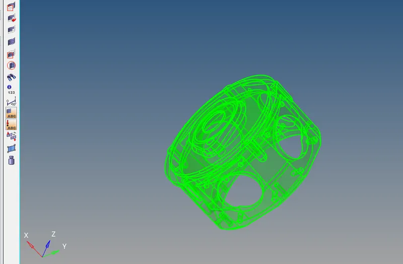
Step 2: As the target element size is 3 units , make the necessary repair on the surface so that the elements will not fail for the minimum element criteria.
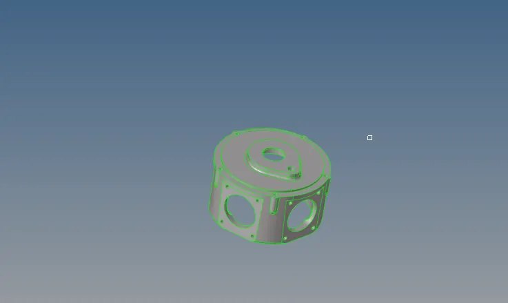
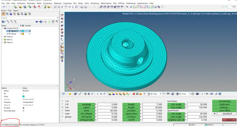
Step 3: Generate the 3 mesh by selecting the volume tetra mesh method by command 3D--> tetramesh-->volume tetramesh .
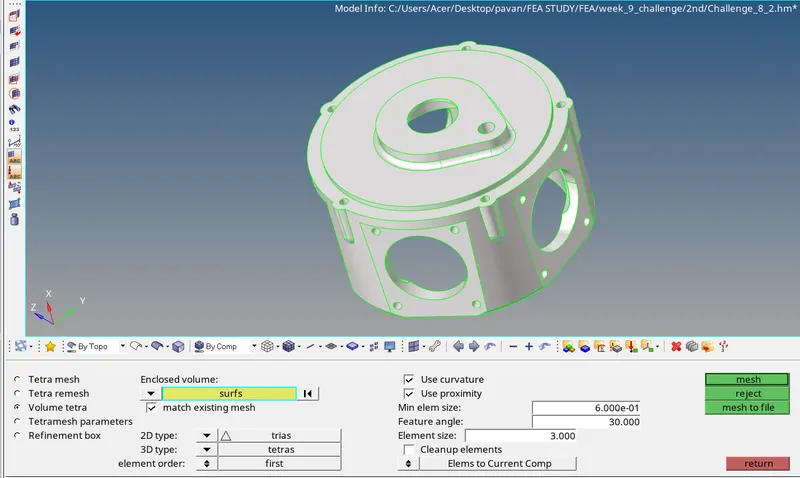
STEP 4: It is then checked for the tet collapse using the command tools--> check elements--> tet collapse .Below is the component that is 3d meshed .
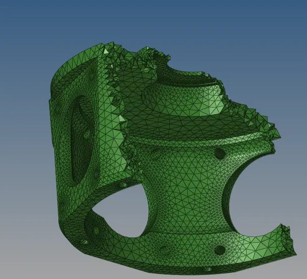
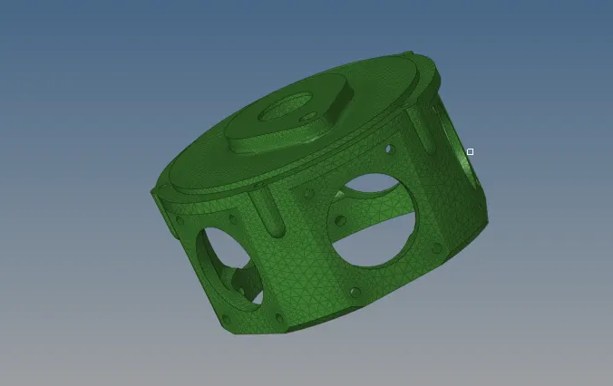
Conclusion : It is learned that the 3d tetramesh can also be generated by using the direct volume tetramesh instead of converting from 2D to 3D elements.
MODEL 3:
OBJECTIVE : Generate the 3D mesh for the given component using the method of volume/Quick tetramesh with the given quality criteria.
procedure:
Step 1 : Import the component and select F to fit it into the GUI area.
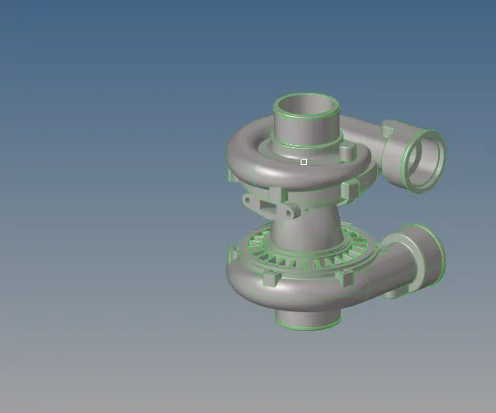
STEP 2: As the component is made of several parts, individually they are meshed .
The middle part is selected and 3D meshing is done by the utility command .
View-->Browsers--> Hypermesh--> utility.
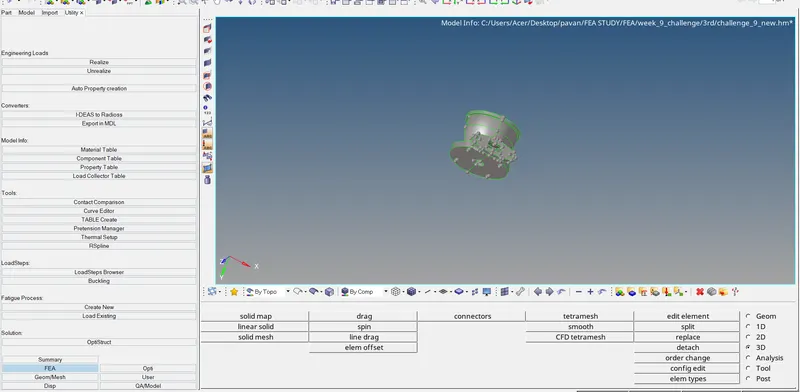
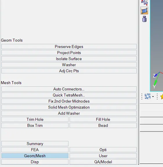
STEP 3: Now select the Geom/Mesh and then give the required parameters and 3D mesh
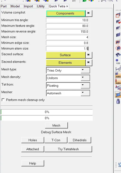
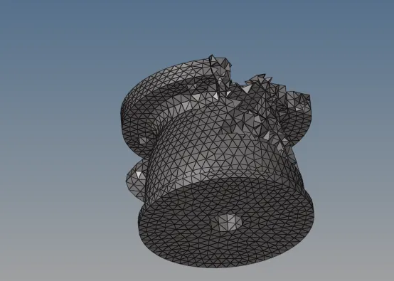
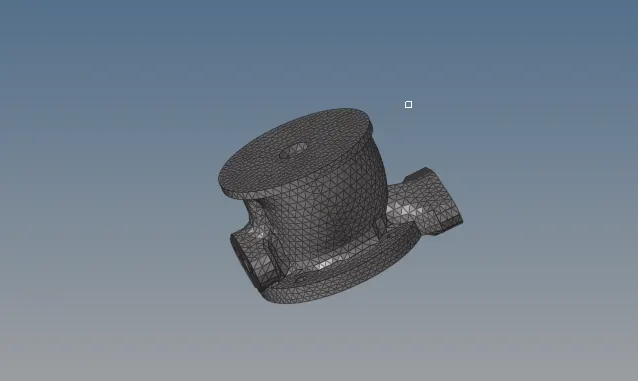
Step 4: The other part of the component is selected and tetramesh is done by the command : 3D--> tetramesh-->volume tetrames. The tetcollapse quality criteria of 0.15 is selected in the parameters.
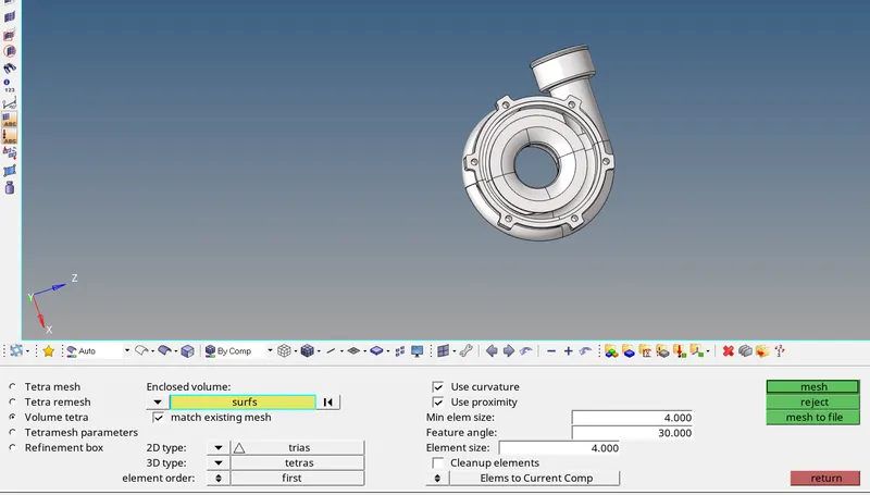
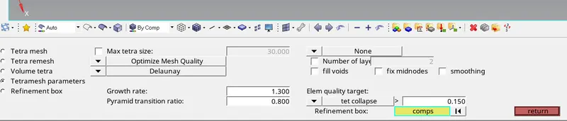
Step 5 : it is then checked for the tet collapse.
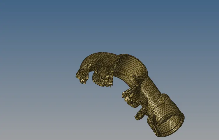
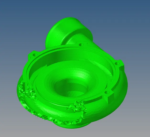
STEP 6: Similarly the other parts of the components are 3D meshed by the volume tetramesh .
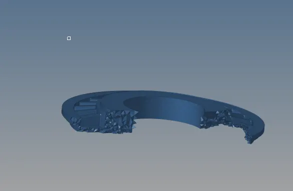
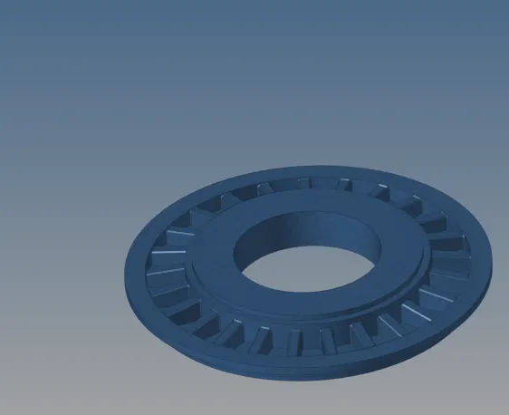
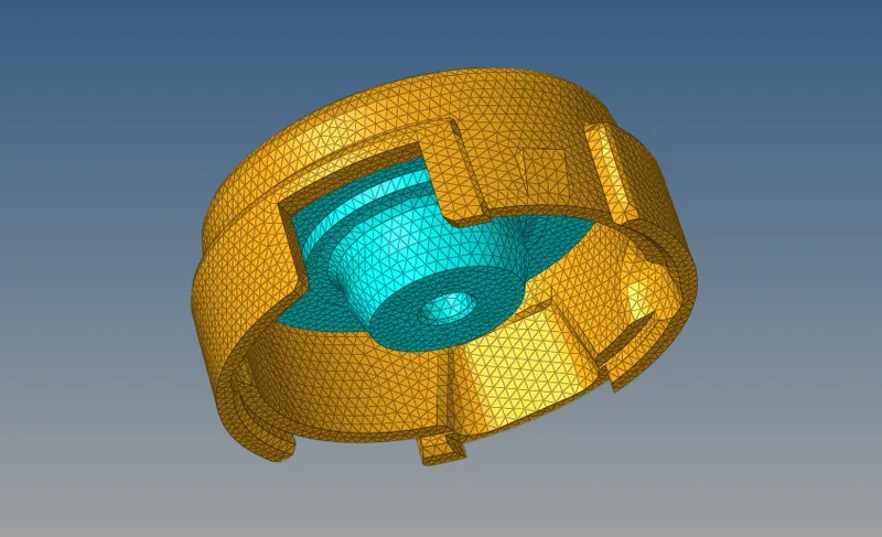
Step 7: The final 3D meshed component is shown as below :
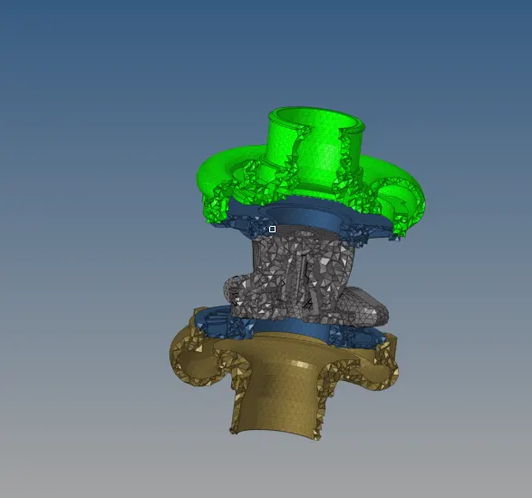
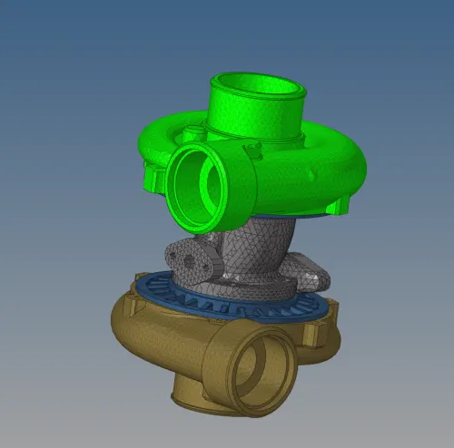
Conclusion : It is learned that the 3d mesh can be generated by using the utility method as well as the volume tetramesh .
overall conclusion : It is learned that the 3D mesh can be genrated by the 3 methods
i) 2D to 3D mesh conversion
ii) Quick/volume tetramesh
iii)utility command.