Week 4-1D Element Creation Challenge
OBJECTIVE : To mesh the component and create a 1D elements with the given cross sectional area and DOF
CAD MODEL :
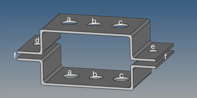
REQUIRED SPECIFICATIONS FOR ELEMENTS AT a, b , c, d , e , f locations are as follows :
a. Rod element:- Translational DOF should be Constrained with RBE2 link
Cross-Section: BOX- Dimension a= 12 mm
dimension b=10 mm
Thickness t= 0.75 mm
b. Beam element:- All DOF should be constrained with RBE3 link
Cross-Section: I Section- Dimension a= 8 mm
Dimension b= 10 mm
Dimension c= 8.5 mm
Thickness t1= 0.75 mm
Thickness t2= .6 mm
Thickness t3= .6 mm
c. Bar element:- Constrain only x and y DOFs With RBE3 link
Cross-section: X section- Dimension DIM1= 5 mm
Thickness DIM2= 1.2 mm
Dimension DIM3= 10 mm
Thickness DIM4= 1.2mm
d. & e. Apply the mass of magnitude 10 with the RBE2 link
f. Join the two components with Spring elements
PROCEDURE :
STEP 1 : Import the Geometry which is in IGS format from the saved file location. Turn off the DISPLAY FIXED POINTS which is at tool bar area.
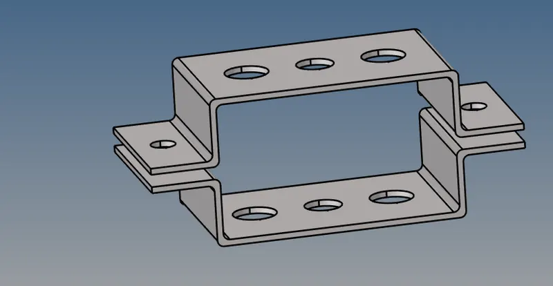
STEP 2 : create a midplane for the top and bottom component separately.
create the seperate components namely TOP BRACKET and BOTTOM BRACKET so that the corresponding midplanes can be seperated and would not be the single component.
COMMAND FOR MIDPLANE : [ GEOMETRY + AUTO MIDSURFACE + SELECT THE TOP SURFACE OF THE COMPONENT + EXTRACT]
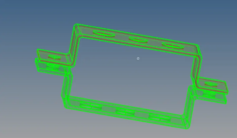
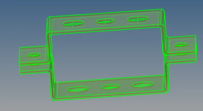
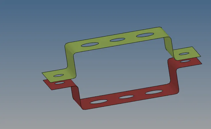
a) MIDPLANE AT TOP BRACKET b) MIDPLANE AT BOTTOM BRACKET
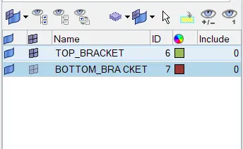
STEP 3 :Now move the TOP AND BOTTOM BRACKET into the respective components named after them in the tab area as shown below
STEP 4 : Create a material (Steel) for the given component
command : [tab area + right click mouse +Create + material +name as steel ] .
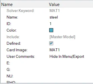
Make sure that card image is MAT1 , since it represents steel in optistruct .The other properties can be edited
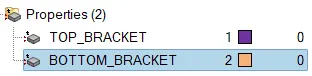
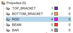
STEP 5 : Create properties for the TOP BRACKET and BOTTOM BRACKET
COMMAND : [TAB AREA + RIGHT CLICK MOUSE + CREATE + PROPERTIES + RENAME :TOP_BRACKET]
[TAB AREA + RIGHT CLICK MOUSE + CREATE + PROPERTIES + RENAME :BOTTOM_BRACKET]
STEP 6 : Linking the property with the material
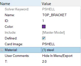
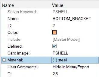
Click on the individual property and choose the card image as pshell and material as Steel
Note : The thickness of the components (top and bottom) can be varied
| SL NO | PROPERTY | CARD ID | THICKNESS |
| 1 | TOP_BRACKET | Pshell | 2 |
| 2 | BOTTOM_BRACKET | Pshell | 2.5 |
STEP 7 : Assign the property to the component
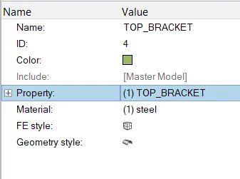
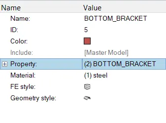
when the property is assigned to the component , the material for top and bottom components will be added automatically.
STEP 8 : MESHING THE COMPONENT
a) Analyze the geometry and create a washer split on of offset of 5mm at the hole region for the smoother mesh on both the top and bottom bracket.
Command : [Geometry + quick edit +
Inorder to add 1D elements we need nodes. Threfore 2D meshing is done with size of 5 units.
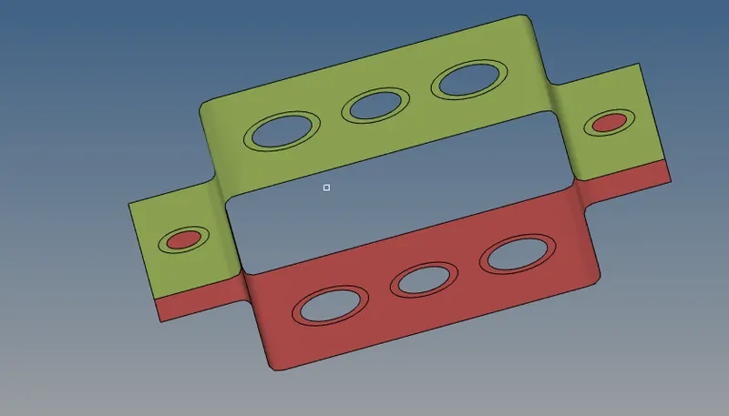
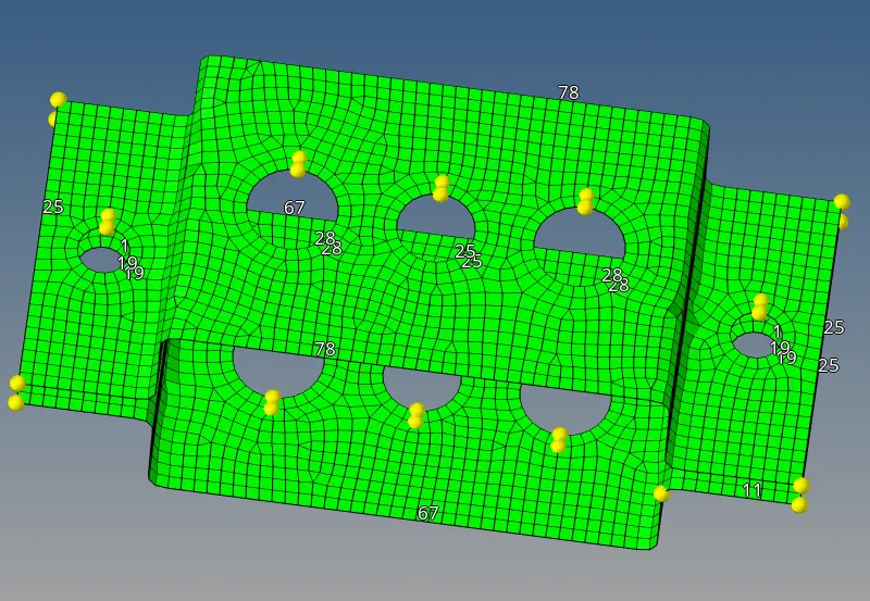
b) Perform the 2D mesh (Automesh) with element size of 5 units with mixed element type.
Command : [2D +automesh + surface + mesh ]
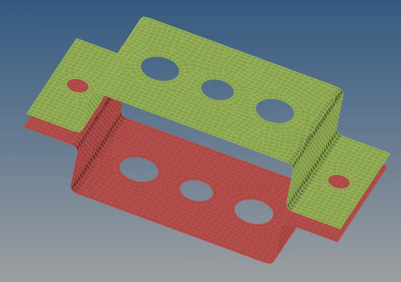
STEP 9 : Create RBE2(rigids) and RBE3 links.
Create the RBE2 (rigids) and RBE3 links with the respective DOF at respective holes locations
command for RBE2 link: [1D+ rigids + set dependent nodes-->multiple ; independent nodes-->calculate node + choose DOF+nodes by path + create]
command for RBE3 link : [1D : RBE3 + dependent -->calculate node ; independent -->nodes + choose DOF+ nodes by path + create )
HOLE LOCATIONS :
a) create RBE2 link at the hole locations (a) on both top and bottom brackets and at the hole locations (d) and (e) with the TRANSLATIONAL DOF CONSTRAINED.
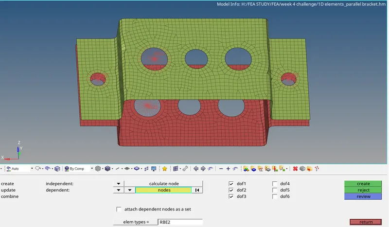
b) Also create RBE3 link at the hole location (b) on both top and bottom brackets with all of the DOF CONSTAINED.
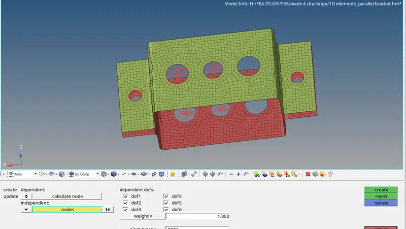
C) Now create the RBE3 link at the hole location (c) on both top and bottom brackets with constraned DOF at X and Y only
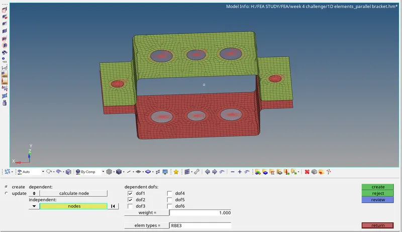
STEP 10 : Create cross sections using HYPERBEAM
Use the command HyperBeam to Create cross section of BOX at hole location(a) Joining the RBE2 links of both Top and Bottom bracket.
Command: [1D + HyperBeam + standard section + select section type : + create]
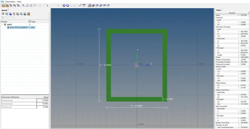
a) ROD CROSS SECTION
Similarly create cross sections of BEAM element : I section , Bar element : X section
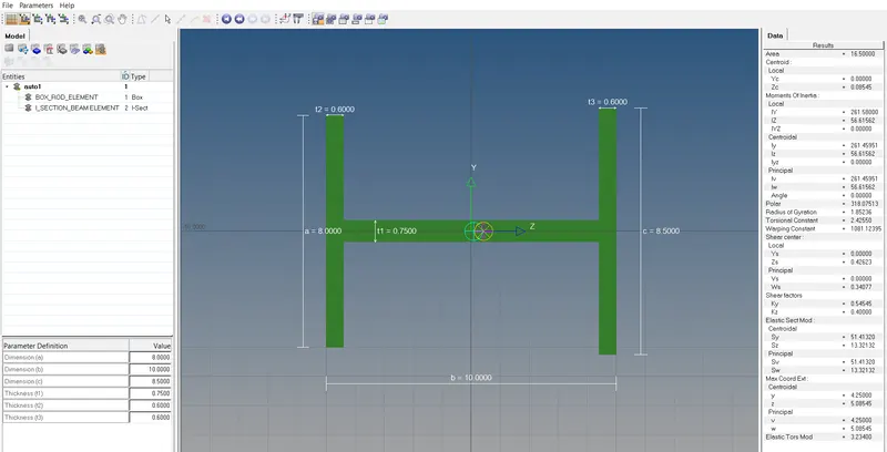
b) BEAM CROSS SECTION
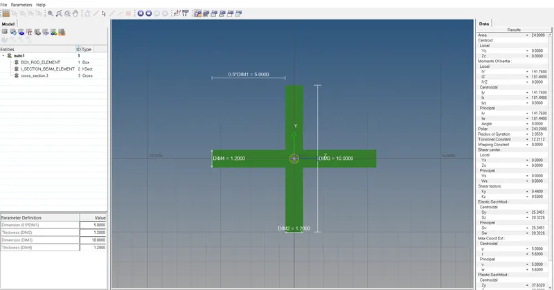
c) BAR CROSS SECTION
STEP 11 : Now create the ROD , BEAM and BAR elements at hole locations (a) , (b) and (c) respectively.
create the rod element by Command : [1D + rods +select nodes + element type : CROD +Create]
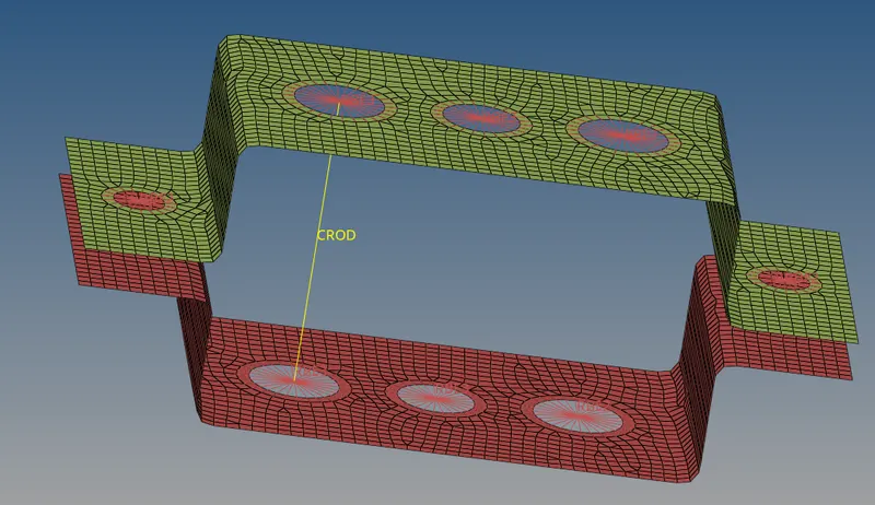
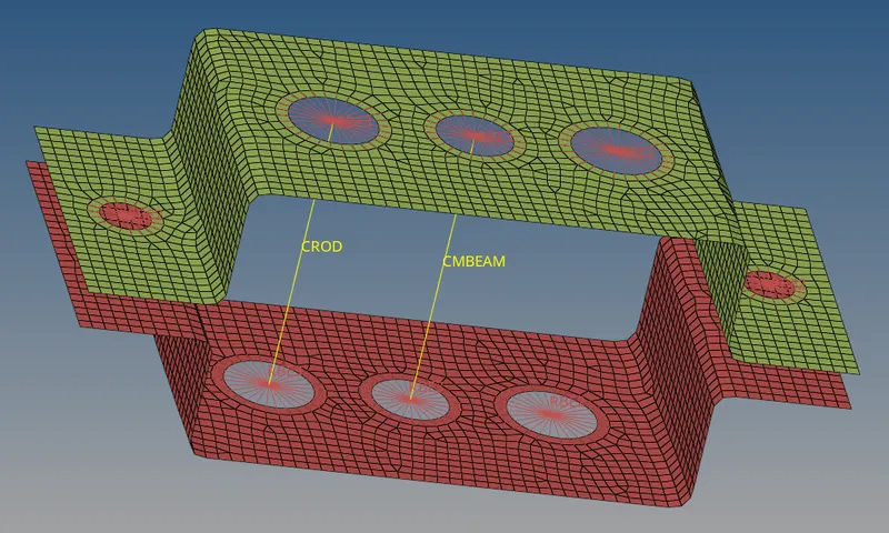
Create the BEAM element by the command : [1D +bars +select nodes +element type : C BEAM ]
Bar element is also similar to the Beam but select the element type to CBAR
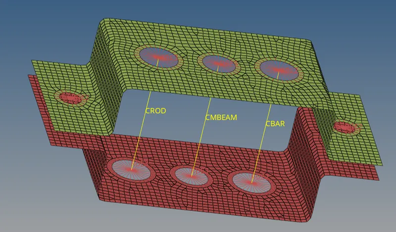
STEP 12 : ASSIGN THE CROSS SECTION TO THE ELEMENT
To assign the cross section to the element , the property for ROD , BEAM and BAR element is to be created and update the CARD IMAGE and choose the cross section.
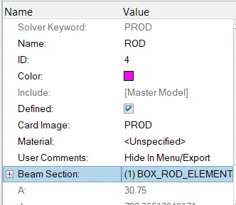
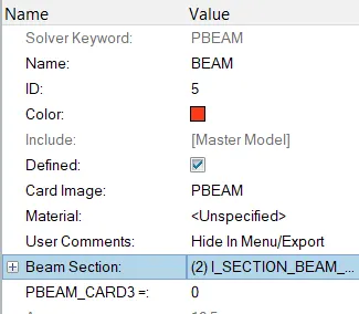
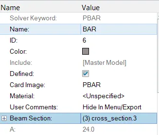
Now update the properties to the rods, bars and beams .
The cross sections of the element can be viewed by the option 1D Detailed Element Representation.
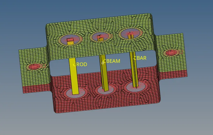
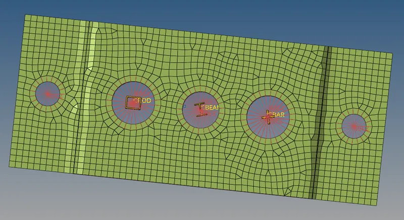
The cross section of BOX, I and Cross(X) are shown below in the top view.
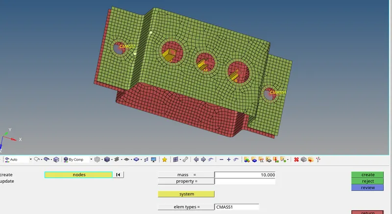
STEP 13 : Add MASS ELEMENT
The mass element type of CMASS1 of magnitude 10 is added at the locations (d) and (e)
command : [1D+mass + select nodes + element type : CMASS1 + Magnitude: 10 units +create]
STEP 14 : Add Spring ELEMENT
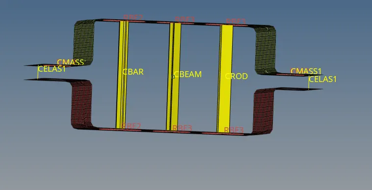
The spring element of CELAS1 type is added at both the extreme ends as shown below with the command :[1D+ spring +select nodes +create]
RESULT and CONCLUSION :
FINAL IMAGE :
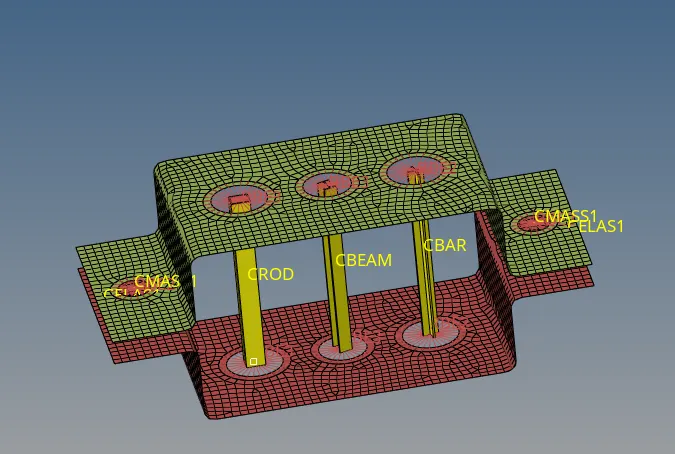
The Given component is 2D meshed and the 1D elements such as RODS, BEAMS and BARS of respective cross sections Box , I and X (Cross) sections are added at the specified locations and special elements like RBE2 link and RBE3 links elements are also added. The major difference between RBE2 and RBE3 is also studied.