Week 8:- 3D Finishing - Challenges 1
Week 8:- 3D Finishing - Challenges 1
1) What do you understand by the 3D finish process?
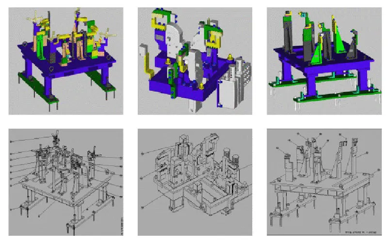
The 3D documentation for a BIW fixture design typically includes 3D models of the fixture components and the body
components that the fixture is designed to hold. The documentation must include detailed drawings,
assembly instructions, and other technical specifications.
Overall, 3D documentation plays an important role in ensuring the accuracy, efficiency, and quality of BIW fixture design
and manufacturing processes.
a) All hiles to be checked with referances to tolarenaces and nominality.
b) Ease of assembly has to be checked in this process.
c) The gaps between the different units to be checked to ensure the proper individual working of different units.
d) All Fasatners has to be checke properly with respect to type of holes either hole is simple hole, threder hole or counter hole.
e) All fasteners standrs has to be cheecked in this process.
f) All units must be idetified difrently so that easy to assemble.
g) 3D models can be used to perform simulations and analyses to determine the fixture's strength, durability, and
performance under various conditions.
Documentation: 3D models can be used to generate technical documentation, including detailed drawings, assembly
instructions, and specifications. This documentation is critical for the manufacturing process, as it guides the assembly
of the fixture and ensures that it meets all the required specifications.
In summary, 3D documentation plays an important role in BIW fixture design by enabling designers and engineers to
visualize, analyze, and document the fixture accurately and efficiently. It helps to improve the accuracy and quality of
the final product while reducing manufacturing time and costs.
2) What are the points need to be taken care of while finishing the design?
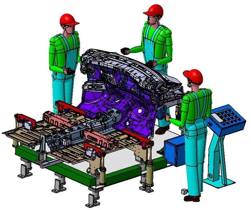
There are several key points that need to be taken care of while finishing the BIW (Body in White) fixture design to ensure
that the finished fixture meets the desired specifications and functions effectively during assembly. Some of these key
points include:
a) Surface finish: The surface finish of the fixture should be uniform, smooth, and free of any scratches, burrs,
or other defects. Any deviations from the desired surface finish should be identified and corrected using appropriate
finishing techniques such as polishing, sanding, or coating.
b) Tolerance: The fixture should be designed with the correct tolerances to ensure that it fits and holds the body
components accurately and securely during assembly. These tolerances should be carefully reviewed and
adjusted as necessary during the finishing process to ensure that they are met.
c) Material selection: The material used in the fixture should be carefully selected based on the application,
environment, and required durability. The material should be tested for any defects or weaknesses and treated
appropriately to ensure that it can withstand the stresses of assembly operations.
d) Assembly points: The fixture should be designed with appropriate assembly points to ensure that it can be easily
and securely attached to the assembly line. These assembly points should be carefully reviewed and adjusted as
necessary during the finishing process to ensure that they are accurate and effective.
e) Verification: The finished fixture should be carefully verified against the design specifications and any
necessary adjustments made to ensure that it meets all the required tolerances and functionality.
Overall, finishing the BIW fixture design requires careful attention to detail and adherence to the design
specifications. By ensuring that the surface finish, tolerances, material selection, assembly points, and verification
process are all carefully managed, the finished fixture will be more accurate, durable, and effective during
assembly operations
3) What are rough Locators & what is their use?
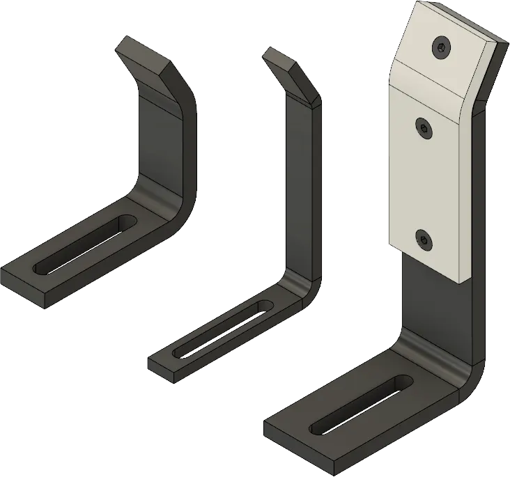
In BIW fixture design, rough locators are temporary fixtures that are used to locate and hold the body components
in place during the assembly process. They are called "rough locators" because they provide a general positioning
of the body components, but do not provide the precise alignment and orientation required for final assembly.
Rough locators are typically made from inexpensive and easily machinable materials such as wood, plastic,
or soft metal. They are designed to be easily and quickly fabricated and installed, allowing for rapid assembly o
f the body components.
The use of rough locators is beneficial in several ways:
a) Cost-effective: Rough locators are inexpensive to produce, which makes them an affordable option for temporary
fixtures in the assembly process.
b) Rapid assembly: Rough locators can be quickly installed and removed, allowing for fast and efficient assembly
of the body components.
c) Adjustable: Rough locators can be easily adjusted or modified to accommodate variations in the body
components or assembly process.
d) Reduced risk of damage: The use of rough locators reduces the risk of damage to the body components
during the assembly process, as they provide a temporary and less rigid hold compared to the final fixtures.
Overall, the use of rough locators in BIW fixture design can help to improve the efficiency and accuracy of the
assembly process while reducing the overall cost of fixture design and manufacturing. However, it is important to
note that rough locators are not suitable for final assembly and must be replaced with more precise fixtures before
the final assembly process.
4) What are the points you need to consider while designing a rough locator?.
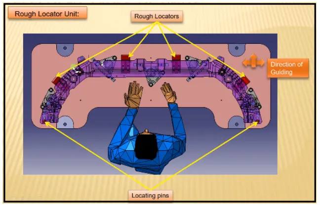
When designing a rough locator in BIW fixture design, there are several key points that should be considered to
ensure that the rough locator is effective and meets the desired specifications.
Some of these key points include:
a) Material selection: The material used for the rough locator should be easy to machine,
inexpensive, and able to withstand the forces applied during the assembly process. Common materials used for
rough locators include wood, plastic, or soft metals such as aluminum.
b) Part positioning: The rough locator should be designed to hold the body components in the correct position and
orientation during assembly. Rough locator has to be placed in the same angle of the car part edge with minimum
distance of 2.5 mm from the edge of car part, so it should no damage panel.
c) Accessibility: The rough locator should be designed for easy installation and removal during the assembly process.
This can include features such as slots or holes for fasteners or handles for easy handling.
d) Flexibility: The rough locator should be designed with some degree of flexibility or adjustability to accommodate
any variations in the body components or assembly process.
e) Rough locator : should be designed with entry angle for the car panel. Generally it ranges between 30-45 degree.
By considering these key points, designers can ensure that the rough locator is effective, efficient, and meets the
desired specifications for the BIW fixture design. It is important to note that rough locators are temporary fixtures and
should be replaced with final fixtures before the final assembly process.
5) What is the gun study process?
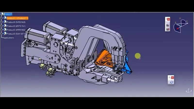
In BIW (Body in White) manufacturing, the gun study process is a simulation technique used to analyze the performance
of automated welding guns. The gun study process is a critical step in ensuring the quality of the welds in the final product
and involves the following steps:
a) Gun selection: The appropriate welding gun is selected based on the type of joint, material thickness, and other
relevant factors.
b) Gun calibration: The welding gun is calibrated to ensure that it is operating within the specified parameters for voltage,
amperage, and wire feed speed.
c) Gun path programming: The welding gun path is programmed to ensure that it follows the correct path along the joint
and maintains the correct orientation and distance from the joint.
d) Virtual simulation: A virtual simulation is performed using software to simulate the welding process and analyze the
performance of the welding gun. The simulation helps to identify any potential issues or problems with the gun path or
welding parameters.
e) Validation: The optimized welding parameters and gun path are validated through actual welding tests to ensure that
the weld quality meets the desired specifications.
The gun study process is critical for ensuring the quality of the welds in BIW manufacturing. By performing a virtual
simulation of the welding process and optimizing the welding parameters and gun path, manufacturers can ensure that
the welds are strong, consistent, and meet the desired specifications for the final product.
6) What re the points need to consider during the gun study?

During the gun study process in BIW (Body in White) manufacturing, there are several key points that should be considered
to ensure that the welding process is optimized and the weld quality meets the desired specifications. Some of these key
points include:
a) Joint design: The joint design should be carefully considered to ensure that it is appropriate for the material, thickness,
and type of welding process being used.
b) Welding parameters: The welding parameters, including voltage, amperage, and wire feed speed, should be optimized
to ensure that the welds are strong and consistent.
c) Gun path programming: The welding gun path should be programmed to ensure that it follows the correct path
along the joint and maintains the correct orientation and distance from the joint.
d) Weld bead size and shape: The size and shape of the weld bead should be carefully considered to ensure that it is
appropriate for the joint design and welding process being used.
e) Material preparation: The material should be properly prepared prior to welding to ensure that it is clean and free from
any contaminants that could affect the quality of the welds.
f) Cooling time: The cooling time between welds should be carefully considered to ensure that the welds cool sufficiently
and are not subjected to excessive heat, which could affect their strength and consistency.
g) Weld quality testing: The welds should be tested for quality using non-destructive testing techniques such as ultrasonic
testing, X-ray testing, or visual inspection to ensure that they meet the desired specifications.
By considering these key points during the gun study process, manufacturers can ensure that the welding process is
optimized and the weld quality meets the desired specifications for the final product. This helps to ensure that the final
product is strong, durable, and safe.
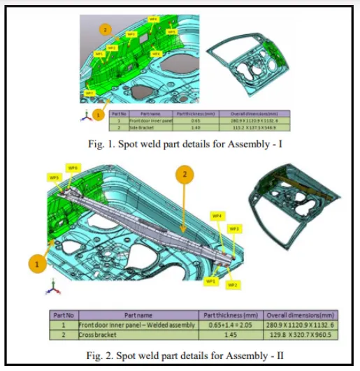
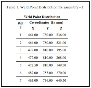
Table 1 with respect to the body line of car.
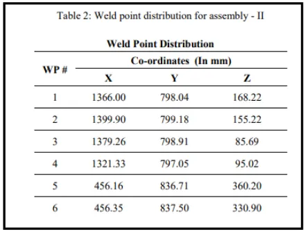
The weld spot locations with respect to the body line of car are as shown in Table 2.
7) What is pneumatic routing?
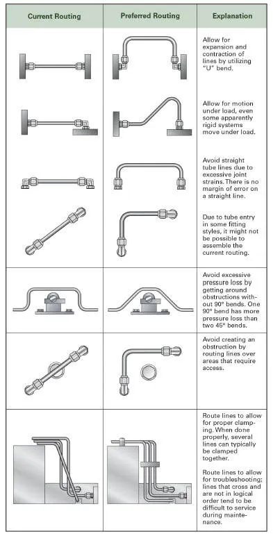
In BIW (Body in White) manufacturing, pneumatic system routing piping refers to the process of designing and routing
the pipes and tubing that are used to carry compressed air throughout the manufacturing facility or production line.
The pneumatic system routing piping process is an important part of designing and implementing a compressed air system,
as it helps ensure that the air is delivered to the appropriate equipment and tools in a safe and efficient manner.
Piping and tubing design: The pipes and tubing used to carry compressed air are designed to ensure that the air is
delivered to the appropriate equipment and tools in a safe and efficient manner. This may involve designing the piping
and tubing to minimize pressure drops and ensure that the air lines do not interfere with other equipment or
production processes.
Installation: The pipes and tubing are installed according to the design and routing plans. This may involve running the
pipes and tubing overhead or underground, using support brackets and hangers to secure the lines, and connecting the
lines to the appropriate equipment and tools.
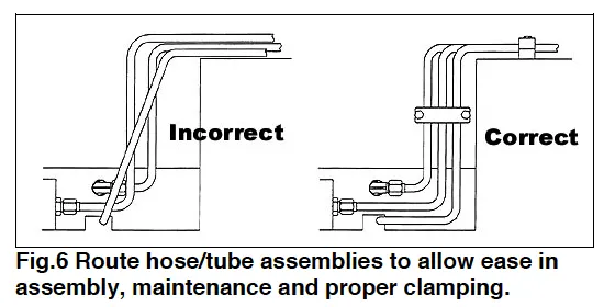
Guidelines for tube line routing:
a) Minimize pressure drop: The pneumatic tubing should be routed in a way that minimizes pressure drop. To minimize
pressure drop, keep the tubing as straight as possible and avoid sharp turns.
b) Avoid kinks and bends: Kinks and bends in the tubing can restrict the flow of air and cause blockages. To avoid this,
use tubing with a large enough diameter to allow for the necessary air flow.
c) Use support brackets: Support brackets should be used to secure the tubing and prevent it from sagging or vibrating.
This helps to maintain the integrity of the tubing and prevent leaks.
d) Avoid contact with other equipment: The pneumatic tubing should be routed in a way that avoids contact with other
equipment or components in the manufacturing process.
e) Protect the tubing from damage: The tubing should be protected from damage caused by impact or abrasion.
f) Use appropriate fittings: The fittings used to connect the tubing should be appropriate for the specific application and
pressure requirements of the system. Improper fittings can cause leaks or reduce the efficiency of the system.
8) What is the solenoid valve?
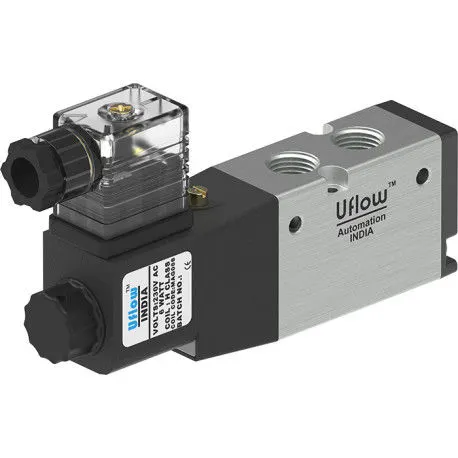
A solenoid valve is an electro-mechanical device that is used to control the flow of fluids, such as air, water, or gas,
in a system. It works by using an electric current to generate a magnetic field, which then opens or closes a valve
that controls the flow of fluid.
A solenoid valve typically consists of a coil of wire, a plunger or piston, and a valve body. When an electric current is
passed through the coil, it creates a magnetic field that causes the plunger or piston to move. This movement either
opens or closes a valve within the valve body, allowing or blocking the flow of fluid through the system.
Solenoid valves are commonly used in a variety of applications, including:
a) Controlling the flow of water or gas in plumbing systems
b) Regulating the flow of air in pneumatic systems
c) Controlling the flow of refrigerants in air conditioning and refrigeration systems
d) Controlling the flow of fuel in automotive and industrial applications
There are different types of solenoid valves available for different applications, including direct-acting valves,
pilot-operated valves, and proportional valves. Direct-acting valves are simple and reliable, while pilot-operated
valves offer higher flow rates and proportional valves offer more precise control of fluid flow.
9) What is the valve bank?
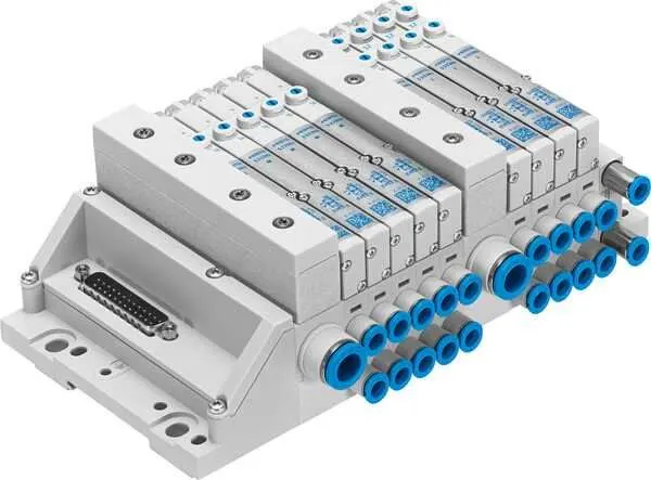
A pneumatic valve bank is a collection of pneumatic valves that are arranged in a specific configuration to control the flow
of compressed air in a pneumatic system. The valve bank typically consists of a manifold that houses multiple individual
valves, which can be operated independently or in combination with one another.
Valve banks are commonly used in automated manufacturing systems to control the movement of pneumatic actuators,
such as cylinders, grippers, and rotary actuators. By using a valve bank, a system can control the flow of compressed air
to multiple actuators at once, allowing for more efficient and precise control of the system.
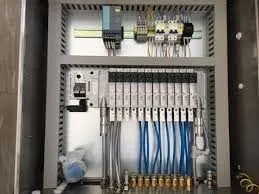
Valve banks can be configured in a variety of ways, depending on the specific requirements of the system. For example,
a valve bank may have multiple inputs and outputs, allowing it to control the flow of air to multiple actuators at once. It
may also include features such as flow control valves, which allow for precise control of the speed of the actuator
movement.
Overall, pneumatic valve banks are an important component of many automated manufacturing systems, providing
efficient and reliable control of pneumatic actuators for a variety of applications.
10) What is sensor & brief about its application in automation?
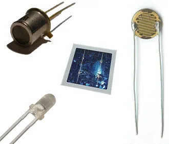
A sensor is a device that detects or measures a physical quantity, such as temperature, pressure, or motion,
and converts it into an electrical signal that can be read by a computer or other electronic device. Sensors are widely
used in automation to monitor and control various processes, and they play a critical role in ensuring the safety, efficiency,
and accuracy of automated systems.
Sensors are used in a wide range of applications in automation, including manufacturing, transportation, and
building automation. For example:
a) Automation and control systems
b) Manufacturing and quality control
c) Transportation and traffic management
d) Building automation and HVAC systems
e) Healthcare and medical devices
f) Aerospace and aviation systems
g) Robotics and industrial machinery
h) Agriculture and environmental monitoring
i) Home automation and consumer electronics
j) Sports and fitness monitoring
k) Security and surveillance systems
l) Energy management and smart grid systems
11) What are the types of the sensor?
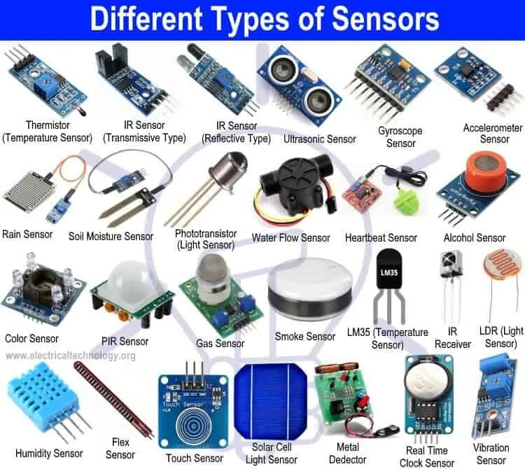
Some common types of sensors used in automation include:
a) Temperature sensors: Used to monitor the temperature of a system or process and adjust it as needed to maintain
optimal conditions.
b) Pressure sensors: Used to monitor the pressure of fluids or gases in a system and regulate the flow as needed.
c) Proximity sensors: Used to detect the presence or absence of objects in a system, and can be used to trigger actions
such as starting or stopping a process or activating a warning signal.
d) Motion sensors: Used to detect the movement of objects in a system and trigger actions such as stopping a process if
an object is in the way.
12) What are the fundamental points that need to consider while designing or selection of sensor?
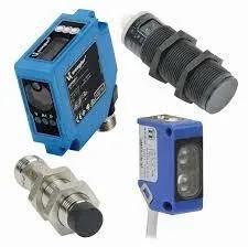
When selecting a sensor for a particular application, there are several important considerations to take into account.
Here are some of the key factors to consider:
a) Measurement range: The measurement range of the sensor should match the range of the physical quantity being
measured. If the range is too narrow, the sensor may not be able to detect changes in the quantity. If the range is too
broad, the sensor may be less precise or accurate.
b) Sensitivity: The sensitivity of the sensor refers to the smallest change in the physical quantity that the sensor
can detect. Higher sensitivity may be desirable for some applications where small changes are important.
c) Accuracy: The accuracy of the sensor refers to how closely the sensor's output matches the true value of the physical
quantity being measured. High accuracy is essential for many applications, such as medical devices and scientific
instruments.
d) Response time: The response time of the sensor refers to how quickly the sensor can detect changes in the physical
quantity. Fast response time may be important for applications where rapid changes are expected.
e) Environmental conditions: The environment in which the sensor will be used should be taken into account. Factors such
as temperature, humidity, and vibration can affect the performance of the sensor.
f) Cost: The cost of the sensor is also an important consideration. Some applications may require a high-end sensor
with advanced features, while others may be able to use a more affordable sensor.
g) Reliability: The reliability of the sensor is important in applications where downtime or failure can have
serious consequences, such as medical devices or aerospace systems.
Overall, selecting the right sensor for a particular application requires careful consideration of these and other factors to
ensure that the sensor provides accurate, reliable, and cost-effective measurements.