Week 8:- 3D Finishing - Challenges 1
3D FINISHING OF BIW FIXTURE
1. What do you understand about the 3D finish process?
The term "3D finish process" refers to completing the design and preparing it for final simulation and 2D details.
The fundamental guidelines for 3D finishing are as follows:
- To guarantee that all of the units can be assembled easily, the nominality of the holes must be examined.
- To guarantee the simple assembly of various parts, the hole diameters and concentricity should be examined.
- The spaces between the various units are examined to make sure each one operates as intended.
- Fasteners are installed according to the size of the hole, and standard color codes are used to distinguish between basic, threaded, and counterbore holes based on customer requirements.
- The most common colors for holes are Cream for machined areas, Yellow for threaded holes, and Violet for simple holes.
- In order for everyone to know which assembly a part will fit in, the assembly and its components must be renamed to give each one a unique identification.
- The model is sent for simulation and 2D detailing following all of the aforementioned procedures.
2. What are the points that need to be taken care of while finishing the design?
- Hole concentricity & hole sizes : All parts are to be checked for hole concentricity and to be confirmed for easy assembly while finishing the parts.
- Machining Area : The machining area in every part should be defined and the machining area should be highlighted by using standard color code.
- Nominality : All units dimensions should be maintained nominal to facilitate easy assembly of the unit.
- Holes coloring standard : Color Code standard as per the customer requirement should be applied in the 3D finishing. Yellow for Threaded Hole, Cream for Machined area, blue for Dowel pin Hole.
- Pneumatic Layout: This method involves assembling several pneumatic pipes to serve as an intake to the pneumatic cylinder. For the units to operate properly, it must be completed correctly.
- Checking for gaps: To prevent conflicts between various units, a suitable distance should be kept between them.
- Implementation of fasteners: Depending on the part's load and requirements, fasteners should be used in every unit.
- Mylar splitting according to panel profile: Mylar splitting needs to be verified at the end of the design process. This should be done in accordance with the fixtures' panel's thickness and shape.
- Standard renaming of parts and assemblies: When the design is complete, parts and assemblies should be renamed appropriately so that each part may be easily identified by its unique identity.
3. What are the rough locators & what is their use?
A rough locator is a component that helps the operator find the automobile panel on the appropriate pins. A rough locator may be made of a custom item or a standard part.
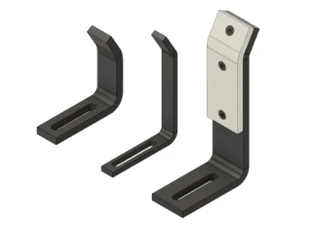
Uses:
- In the automation process, workpieces are located with the aid of rough locators. Locating is the process of specifying the ideal position for the workpiece to be in while it is being worked on by a person, group, or robot.
- The final product's uniformity and appearance are directly impacted by the precision of component location. These elements are therefore crucial to your setup.
- Another name for it is the fool proofing approach. Because the part cannot be loaded incorrectly because of the rough locator. The part can only be loaded in specific directions and orientations because the rough locators are adjusted based on the angle of the corresponding panel.
4. What are the points you need to consider while designing a rough locator?
- A rough locator should be positioned at the automobile panel's margins, where it must provide guidance.
- The rough locator must be positioned at the same angle as the automobile part edge and at least 2 to 5 mm away from the edge.
- The panel should be guided in the direction of pin arrest by a rough locator.
- The panel should be guided by the rough locator 10 to 15 mm before the pin engagement begins.
- The automobile panel's entry angle should be incorporated into the rough locator design. It often falls between 30 and 45 degrees.
- To attach the simple adjustments, the rough locator should have two slots.
- The slots ought to face the direction of the vehicle's part guidance.
5. What is the gun study process?
Welding is a method that is primarily utilized in the automotive business, and any company must constantly develop its requirements. The intricate steel structure of BIW is made out of 300mm to 500mm sheets with intricate shapes that are put together by welding. Reaching the spot weld locations is the initial step before beginning the welding fixture design. The weld spot distribution is used to determine the position and orientation of other crucial fixture components, such as clamps and locators.
Gun research essentially consists of studying the weld gun, which is a portable instrument used for semiautomatic welding of parts of different products. The operation of the gun depends on the part's thickness, size, and other characteristics. Using the 3D software, assess the gun that will be used for spot welding across the panel after studying it.
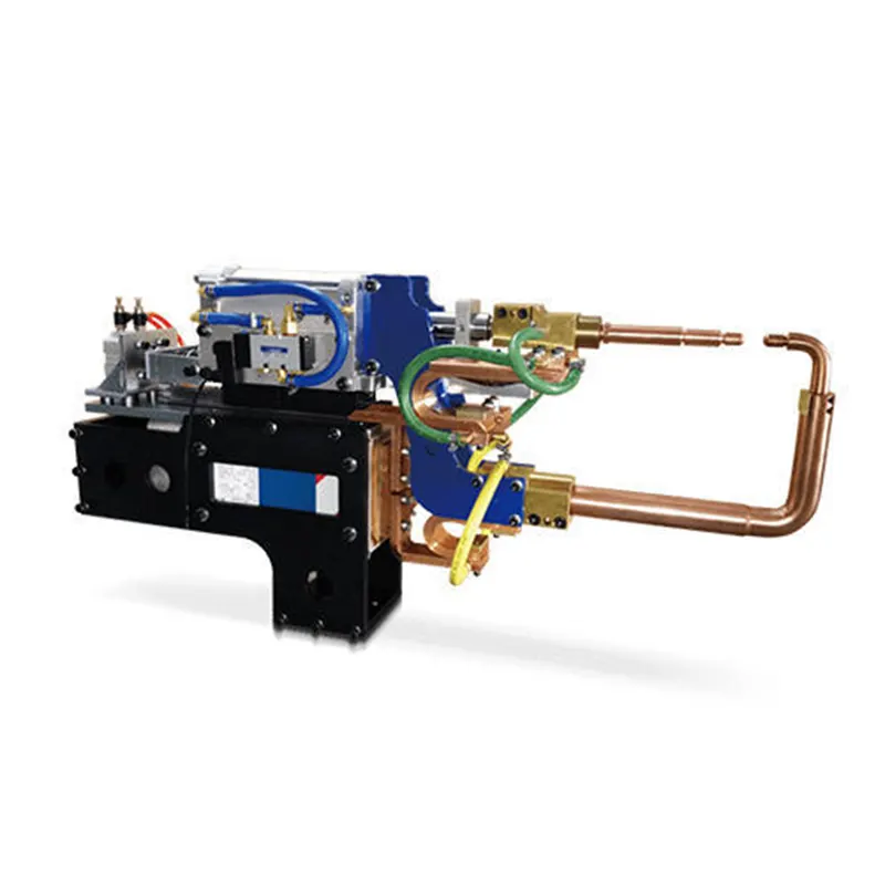
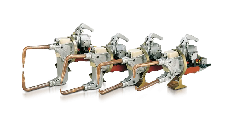
The weld gun position is verified over the designated spot weld spots to determine whether or not the gun falls to the fixture unit. The fixture is made to hold the automobile panel in place. The fixture unit is redesigned or repositioned if the weld gun falls on it, and it is once more verified whether the gun is falling or not. If the cannon hits the fixture unit, the weld spot locations stay the same, but the fixtures are reconfigured. Gun has two different types and they are as follow,
- C- type gun
- X- type gun
6. What are the points need to be considered during the gun study?
Studying a weld gun takes a lot of time, and the amount of weld locations determines how long the welding cycle takes.
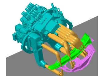
- The weld spot's axis must be normal to the weld surface along the welding direction.
- The total time needed to finish all of the weld spots is determined by the number of weld spots on the panel and the amount of time needed to spot each weld.
- It is possible to mimic the behavior of each model in the work cell over time if we wish to program one or more device models. Sequences are used to code instructions for every device. The devices' motion, manipulation, and action are specified by the sequence. Cycle time for each device associated with sequences can be obtained based on motion type, speed, acceleration, and the distance of each tag point from home location. This method robot cycle time is properly calculated.
- Once every device has been sequenced, a simulation is conducted with "collision check" turned on to ensure that there are no collisions throughout the welding process.
7.What is the pneumatic routing?
Pneumatic systems must to be leak-proof and effective. Occasionally, they aren't because of incorrect tube line routing that was caused by either ignorance, time-saving planning shortcuts, or both. Although it takes time, tube line routing planning can yield significant returns, particularly for intricate systems. After choosing the right fittings and sizing the tube lines, routing should be designed as the following stage of system design.
- Fitting joints should be as accessible as feasible. Assembling, tightening, and maintaining inaccessible joints is challenging and time-consuming.
- To do time-consuming computations like pressure drop, use software tools.
- To accommodate line growth and contraction, use U-bends.
- Incorporate offset bends to provide motion under load, even if the system appears to be "rigid."
- Prefer bends over straight tube lines because a straight line tube assembly without bends, such as the test stand example above, might result in joint discoloration, which could cause leaks.
- Ensure that the routing design provides space for the construction of any necessary connections.
- Reduce pressure drop by avoiding as many 90° bends as you can when navigating around obstacles. Compared to two 45° bends, one 90° curve loses more pressure.
- Lines should be routed around, not over, locations that need frequent maintenance or access.
- Consider clamping when designing routing. Proper clamping follows logically from appropriate design. It is frequently feasible to clamp many wires together.
- Remember maintenance and troubleshooting: avoid crossing lines and concentrate on logical design.
- Reduce the possibility that people will stand or climb on plumbing by designing the tube line routing.
8. What is the solenoid valve?
An electro-mechanically operated valve is called a solenoid valve. The type and properties of fluid that solenoid valves control, the electric current they use, the magnetic field they produce, and the mechanism they employ to control the fluid all vary. The mechanism ranges from rocker actuators, pivoting armature actuators, and plunger-type actuators to linear action.
The valve can be designed with two ports to control a flow or with three or more ports to switch between ports. On a manifold, several solenoid valves can be positioned together. In fluidics, solenoid valves are the most commonly utilized control components. They are responsible for mixing, distributing, dosing, releasing, and shutting off fluids. Numerous application areas contain them. Fast and secure switching, high dependability, extended service life, good medium compatibility of the materials employed, low control power, and compact design are all features of solenoids.
Working:
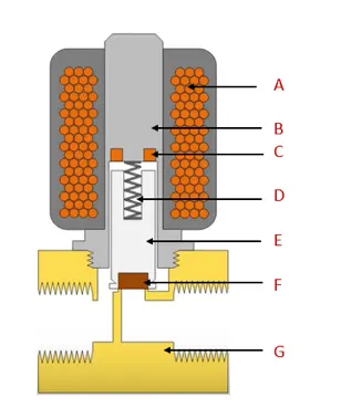
A solenoid and a valve body (G) are the two primary parts of a solenoid valve. The components are depicted in the figure. An iron core known as the plunger (E) is encircled by an electromagnetically inductive coil (A) in a solenoid. It may be typically closed (NC) or normally open (NO) when at rest. A normally closed valve is closed and a normally open valve is open when the valve is de-energized. The coil is activated and produces a magnetic field when current passes through the solenoid. This moves the plunger and overcomes the spring's (D) force by creating a magnetic attraction with it. The plunger is raised when the valve is ordinarily closed, opening the orifice and allowing the media to pass through the valve. The plunger descends while the valve is ordinarily open, obstructing the orifice and halting the media flow through the valve. In AC coils, the shade ring (C) stops humming and vibration.
Components:
- Coil
- Armature
- Shading ring
- Spring
- Plunger
- Seal
- Valve body
9. What is the valve bank?
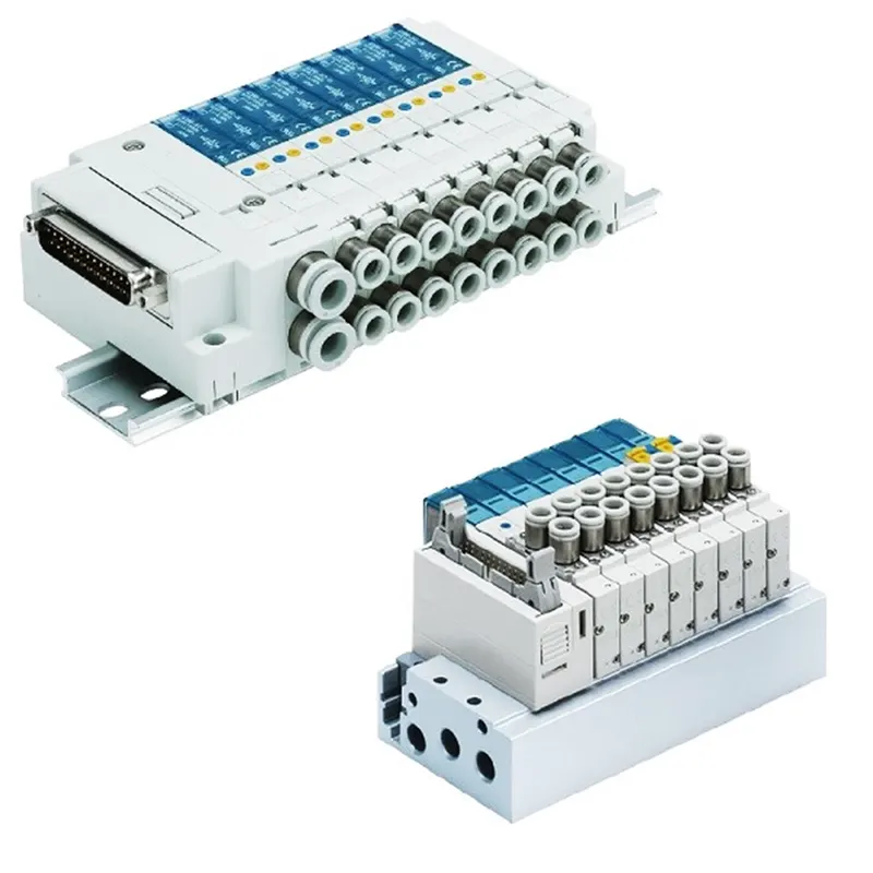
The arrangement of solenoid valves is known as a valve bank. Each solenoid in the valve bank will have its own vent passageways, a single servo line to each pneumatic valve, and a shared inlet port. The feed of high pressure servo air to a single pneumatic valve is independently controlled by each solenoid valve on the solenoid bank. In order to enable servo air to reach the servo port of the valve, the matching solenoid is selectively energized. The solenoid is de-energized to release the valve's servo port to ambient in order to restore the valve to its fail-safe state.
Common characteristics of the valve bank:
- They are made to withstand severe vibration levels.
- For light weight, it uses manifolds made of aluminum alloy.
- These are made to withstand extreme temperatures.
- The design architecture makes it simple to choose between two and six solenoid valves.
10. What is a sensor? & brief about its application in automation.
A sensor is a device that measures or detects a physical property and then records, indicates, or reacts to it in some other way. A sensor unit is a device made to use electrical sensors to detect automobile panels. Sensor data is sent to the PLC, which uses this signal to carry out the following action. Since the sensor is highly sensitive and easily damageable, a cover is supplied for its protection.
Sensors are crucial to the industrial automation sector because they enable intelligent and highly automated products. These enable the detection, analysis, measurement, and processing of a variety of changes that take place in the manufacturing sites, such as changes in position, length, height, appearance, and displacement. These sensors meet the requirements of numerous sensing applications by being crucial in anticipating and averting numerous future occurrences.
The several kinds of sensors utilized in industrial automation include the following: sensors that measure things like temperature, inclination, position, photoelectric, ultrasonic, vision, and proximity. Position sensors in general have a wide range of uses. They can be utilized in semiconductor process equipment, robot motion control, tank-level detection, and more. For instance, displacement sensors are utilized in machine tool metrology, assembly line testing, and the precise positioning of objects at the nanoscale level. They are also employed in the measurement of disk drive thickness. In machining, it is frequently utilized.
11. What are the types of sensor?
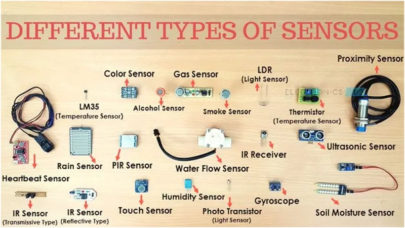
The sorts of sensors that are frequently used in a variety of applications are listed below. Temperature, resistance, capacitance, conduction, heat transfer, and other physical attributes are all measured by these sensors.
- Temperature Sensor.
- Proximity Sensor.
- Accelerometer Sensor.
- Infrared sensor (IR sensor).
- Pressure Sensor.
- light sensor.
- Ultrasonic sensor.
- Smoke, Gas and Alcohol Sensor.
- Touch Sensor.
- Color sensor.
- Humidity Sensor.
- Tilt Sensor.
- Level and Flow Sensor.
12. What are the fundamental points that need to be considered while designing or selecting a sensor?
- A sensor unit is a device that uses electrical sensors to detect the automobile panel.
- The PLC will receive the signal from the sensors and use it to initiate the subsequent step.
- Sensors are used to verify whether a panel or component is present.
- It ought to assist in preventing human error.
- Sensor numbers should ideally match the number of panels in an assembly. For instance, at least nine sensors should be used if nine panels are being assembled.
- Sensors ought to be slotted such that they can be adjusted in three different directions.
- The operator should be safe thanks to sensors.
- Fixtures typically use proximity, laser, and photoelectric sensors.