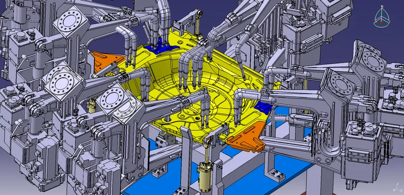
Week 8:- 3D Finishing Challenge 2
Input from previous challenge:
Fig.1 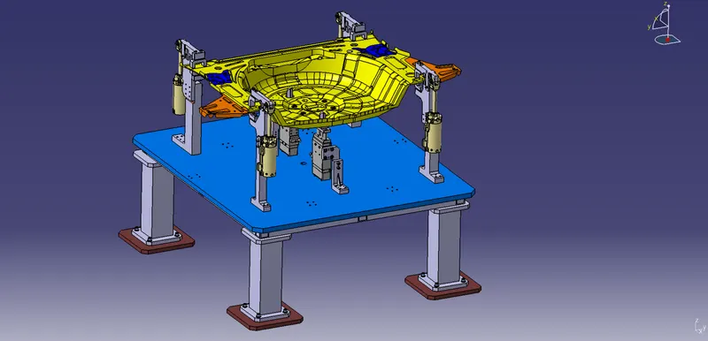
BIW FIXTURE WITH 3D FINISHING AND ROUGH LOCATORS:
Fig.2 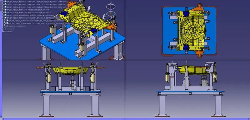
3D FINISHING PROCESS pointers:
- HOLE CONCENTRICITY:
Every holes (dowel, pin, and screw hole) should be concentric with respective mounting body holes.
Fig.3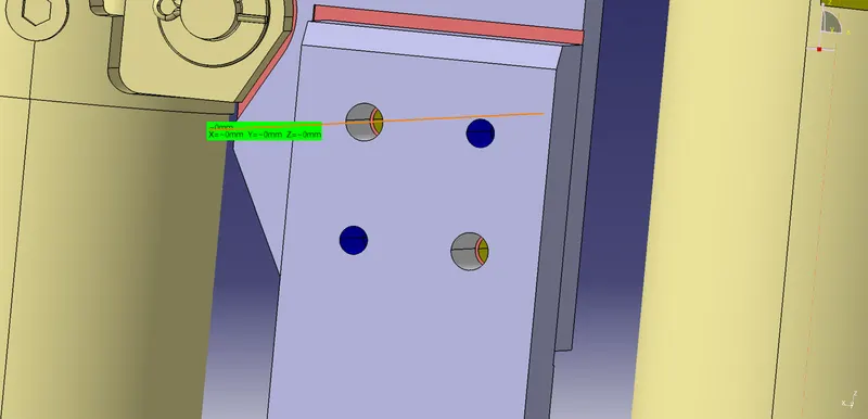
- MACHINING AREA:
Area to be machined for proper alignment and surface contact of mating parts or mounting parts.
The existing surfaces of contacting elements were depressed upto 1mm to 3mm varying on place, use and size of that element.
Example: The contacting area shown below between blade and riser is 1.5mm of machined area (in Reddish pink Fig.4).
It saves the cost of machining as in other case whole blade is to machined for about 1.5mm of depth.
Similar Machined areas were done on various fixture elements across the wholw fixture assembly.
Fig.4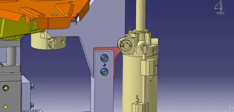
- NOMINALITY:
All the nominalities are measured with reference of a hole present in the base plate. (in red outline Fig.5)
Fig. 5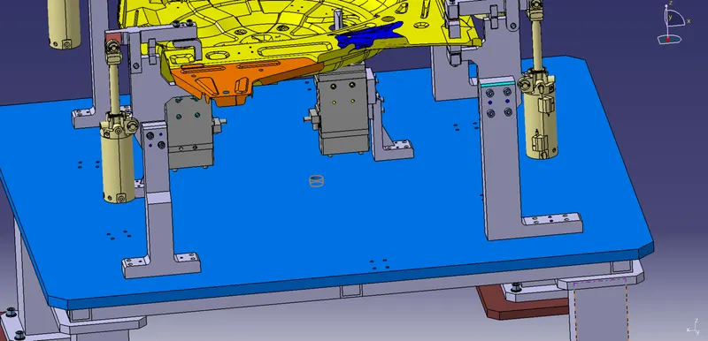
The nominalities of all units mounted on the base plate is shown below.
As all the units elements/parts were designed by taking nominalities in mind, so only units need to be checked for nominalities.
- Swivel clamp unit 1:
Fig.6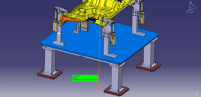
Fig.7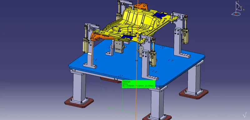
- Swivel clamp unit 2:
Fig.8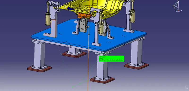
Fig.9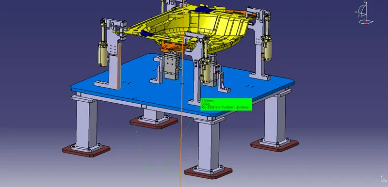
- Swivel clamp unit 3:
Fig.10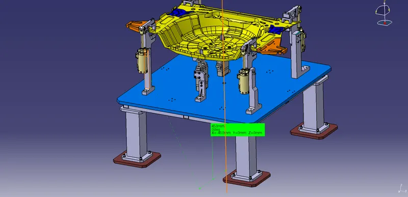
Fig. 11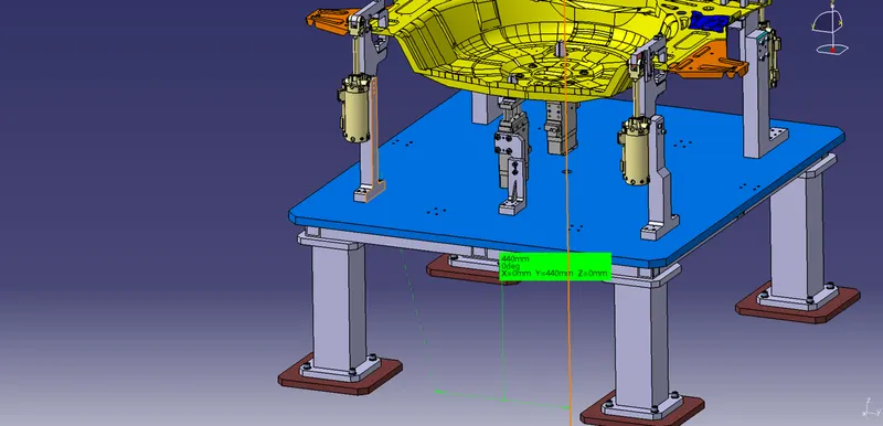
- Pin Unit: Due to pin holes present in the panel not being nominal Therefore nominality cannot be achieved while mounting each pin unit onto base plate.
The Non-nominality is explained by series of picture below.
The distance between the pin holes are not nominal (Fig.12)
Fig.12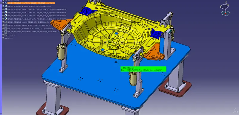
As can be seen (from Fig.13 and Fig.14) the Pin units are concentric to the panel pin hole.
Fig.13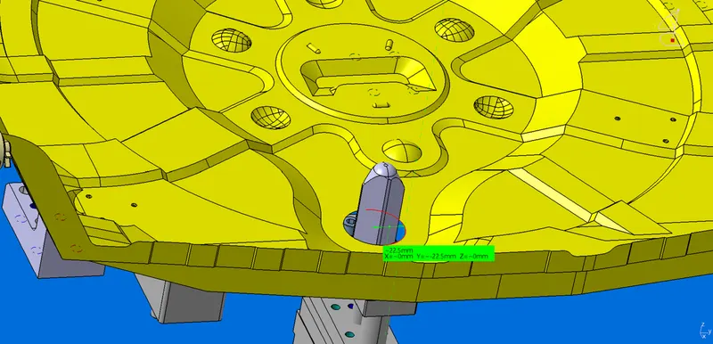
Fig.14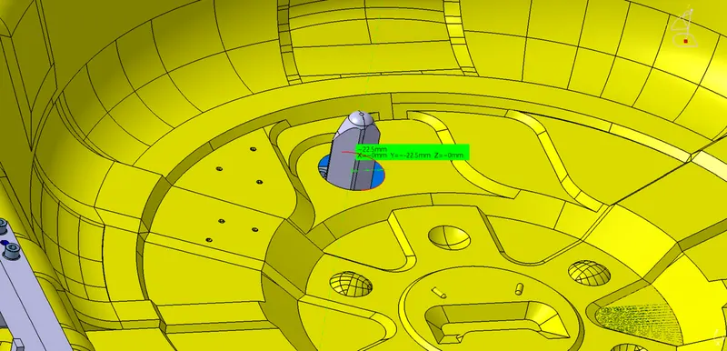
Also the panel is the nominal to the base plate reference hole. (Fig.15)
Fig.15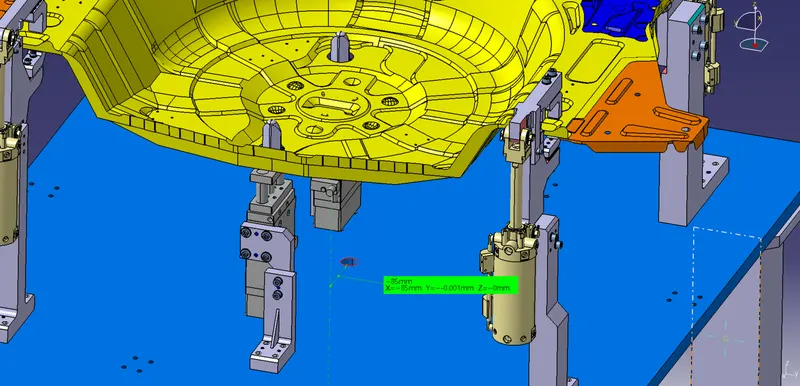
But the pin units are not nominal to the center hole on base plate. (Fig.16 and Fig.17)
Fig.16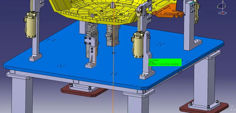
Fig.17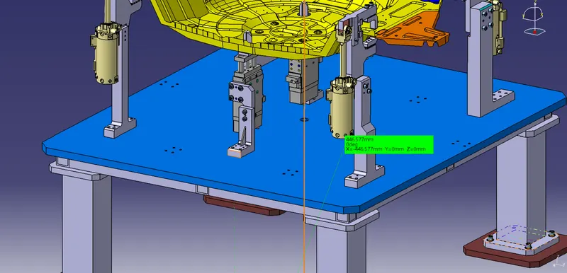
- Swivel clamp unit 1:
- HOLES COLOURING:
BLUE: Dowel holes, WHITE: Unthreaded portion of Screw holes (Fig.18)
YELLOW: Threaded portion of Screw holes (Fig.19)
REDDISH PINK: Machined Area (Fig.20)
PINK: Cylindrical Pin holes (Fig.21)
Fig.18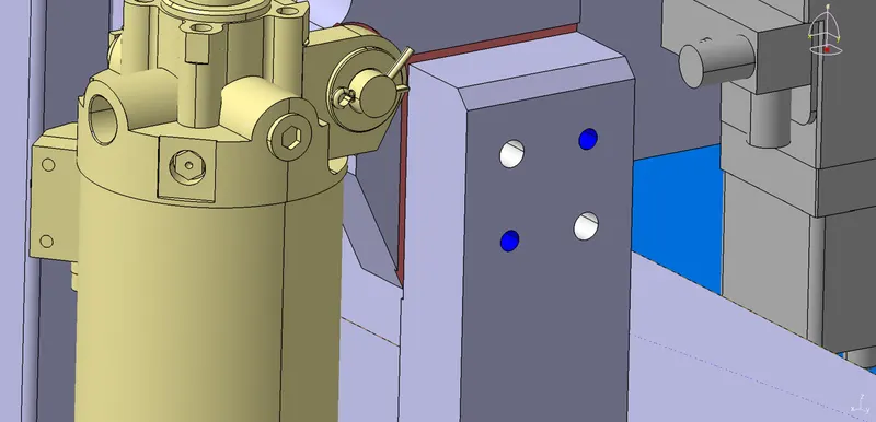
Fig.19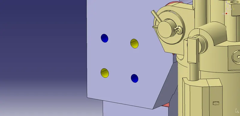
Fig.20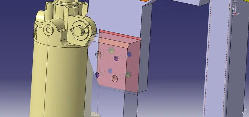
Fig.21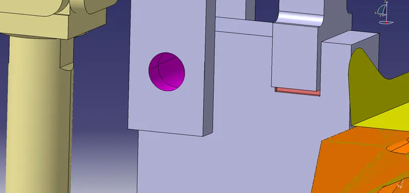
- PNEUMATIC LAY-OUTING:
It generally consist of Pipes from cylinder connected to valve banks and passes through a safety box like structure.
The safety box structure is shown below (In red outline Fig.22)
Fig.22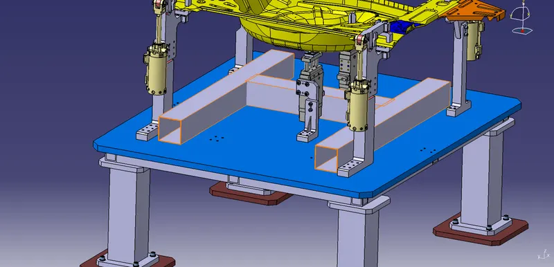
- FASTENER IMPLEMENTATION:
(In red outline Fig.23)
Fig.23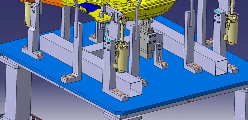
- MYLAR SPLITTING AS PER PANEL PROFILE:
- Swivel clamp unit 1:
Fig.24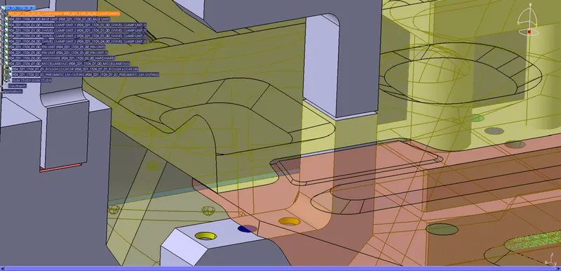
- Swivel clamp unit 2:
Fig.25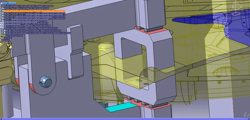
- Swivel clamp unit 3:
Fig.26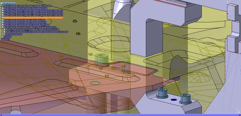
- Swivel clamp unit 1:
ROUGH LOCATORS:
Total 6 RL have been used 2 quantity of Type-I and 4 quantity of Type-II. (in Fig.27)
Fig.27 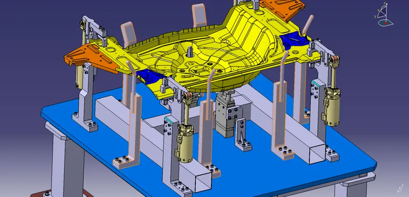
TYPE-I: (In red outline Fig.28)
Fig.28 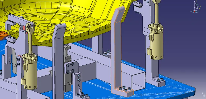
TYPE-II: (In red outline Fig.29)
Fig.29 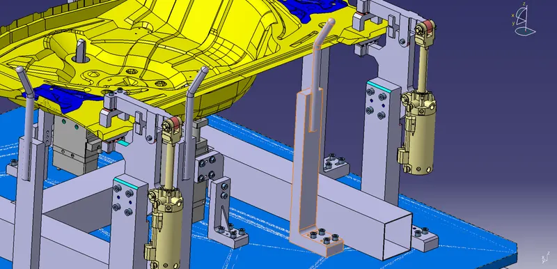
GUN STUDY:
In the gun study done on the panel and various fixture, it can be concluded that the spot welding gun will have enough space with clearance to any part of fixture. (shown in Fig.30)
Fig.30