Week 8:- 3D Finishing Challenge 2
Week 8:- 3D Finishing Challenge 2
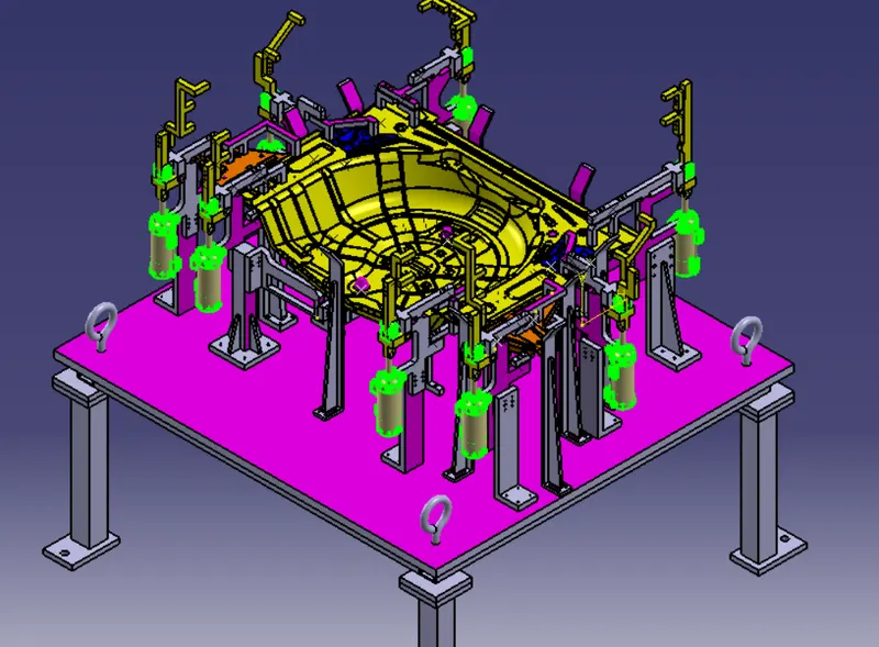
Aim - Perform 3D finish and create Rough locators for the Assembly design created for the challenge on week 7.
Introduction -
BIW fixture, also known as body-in-white fixture, is a specialized tool used in the automotive industry for the assembly
of vehicle bodies. The BIW fixture is a critical component in the manufacturing process as it ensures the accurate alignment
and positioning of various vehicle components during assembly. The fixture is typically made of steel and designed to hold
the car body in place with a series of clamps and supports.
With the help of BIW fixture, manufacturers can ensure that the car body is assembled precisely and with consistency,
which is essential for ensuring the quality and safety of the final product. BIW fixtures are typically customized for
each specific vehicle model, as they need to be able to hold the unique shape and dimensions of the car body
during assembly.
Overall, the BIW fixture plays a crucial role in the manufacturing of automobiles, helping to ensure that the
car body is assembled accurately and efficiently, ultimately leading to a high-quality finished product.
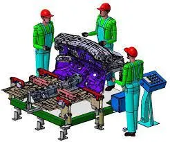
3D Finish -
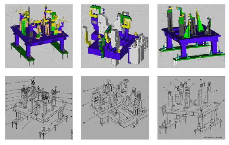
The 3D documentation for a BIW fixture design typically includes 3D models of the fixture components and the body
components that the fixture is designed to hold. The documentation must include detailed drawings,
assembly instructions, and other technical specifications.
Overall, 3D documentation plays an important role in ensuring the accuracy, efficiency, and quality of BIW fixture design
and manufacturing processes.
a) All hiles to be checked with referances to tolarenaces and nominality.
b) Ease of assembly has to be checked in this process.
c) The gaps between the different units to be checked to ensure the proper individual working of different units.
d) All Fasatners has to be checke properly with respect to type of holes either hole is simple hole, threder hole or counter hole.
e) All fasteners standrs has to be cheecked in this process.
f) All units must be idetified difrently so that easy to assemble.
g) 3D models can be used to perform simulations and analyses to determine the fixture's strength, durability, and
performance under various conditions.
Documentation: 3D models can be used to generate technical documentation, including detailed drawings, assembly
instructions, and specifications. This documentation is critical for the manufacturing process, as it guides the assembly
of the fixture and ensures that it meets all the required specifications.
In summary, 3D documentation plays an important role in BIW fixture design by enabling designers and engineers to
visualize, analyze, and document the fixture accurately and efficiently. It helps to improve the accuracy and quality of
the final product while reducing manufacturing time and costs.
Points Need to Be Taken Care of While Finishing the Design:
The following are the points taken into consideration while finishing the design.
- Hole Concentricity and Hole Sizes:
All part holes concentricity and hole sizes are checked for easy assembly while finishing the parts.
- Machining Area:
The machining area in every part should be defined and the machining area should be highlighted by using standard colour code. Machining is to be done on parts to properly Mount with mating parts. Machining only on desired faces reduces cost and save time. And also Machining increases accuracy of dimension. So before going to simulation or detailing machining area should be defined.
- Nominality:
All unit’s dimension should be maintained nominal to facilitate easy assembly of the unit.
- Holes Colouring Standard:
In a 3D finish hole colouring should be done because it helps to identify what type of hole it is. It depends on customer standards. Customer specific colour like:
Dowel hole should be given blue colour.
Threaded hole should be coloured with yellow.
Counter bore, open hole should be given cyan blue colour.
- Pneumatic Lay outing:
Pneumatic lay outing is collection of different pneumatic pipes which work as a inlet to the pneumatic cylinder. It should be done properly for proper functioning of the units.
- Gaps Checking:
The gaps between the different units are checked to ensure the proper individual working of different units.
- Fasteners Implementation:
Fast should be implemented in all the units as per the requirement and load on the part.
- Avoiding Clash Between Different Parts:
Proper gap should be maintained between units to avoid the clashes between the different units.
- Mylar Splitting as Per Panel Profile:
Mylar splitting as for panel profile should be confirmed while finishing the design.
- Proper Renaming of Parts or Assemblies as Per the Standards:
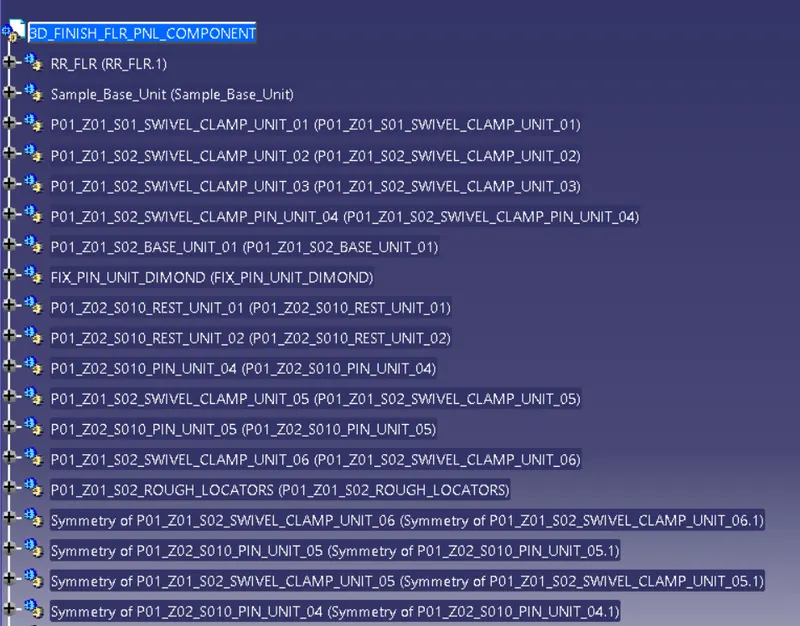
Proper renaming of parts and assembly should be done while finishing the design and hence we can identify each and every part easily with Unique Identification.
Typical parts of the base unit :-
I) Base Plate :-
Base Plate is a machined plate made of steel or Aluminium of thickness 25mm to 40mm on which the holes are drilled to
mount diffrent units like rest units, clamp units, pin units etc.
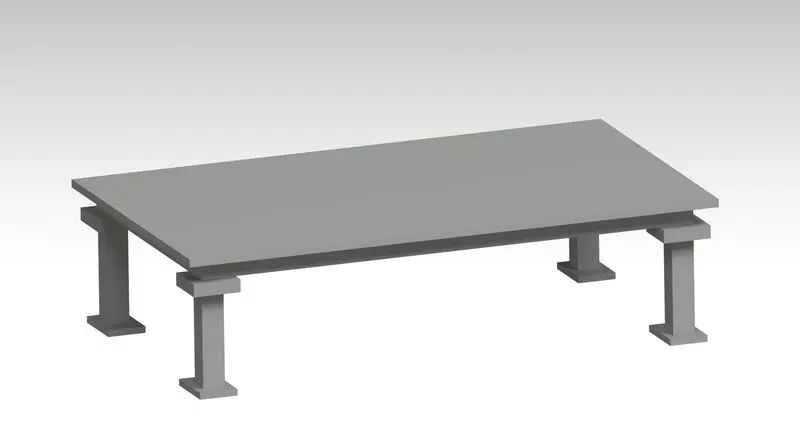
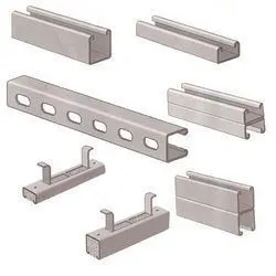
II) Trunking Channel :-
Cable trunking is an enclosure usually with a rectangular cross section, and with one removable or hinged side, that is used
to protect cables and provide space for other electrical equipment. They make electrical ducting and cable trunking
for concealing and securing cabling.
Trunking Channel is a duct that carries all the electrical and pneumatic connections(wires and pipes) for units of the tool.
The standards of trunking sizes :-
50mm x 50mm
150mm x 75mm
75mm x 50mm
150mm x 100mm
75mm x 75mm
150mm x 150mm
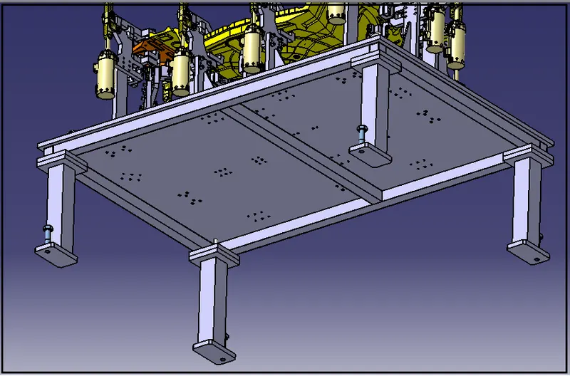
III) Pedestal :-
* It is used to connect the base plate with a floor plate.
* The pedestal can be a standard part or a make part, depending on the size and height of the fixture.
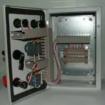
IV) Valve box
Pneumatic valves play an important role in a pneumatic system. They determine how much air passes through and in
which direction. This means that they can be used as control valves, but also as safety valves that shut off the air
supply in dangerous situations or that depressurise the system.
The valves pressurize and exhaust one outlet port to control a single-acting cylinder, or pilot another valve.
V) Measuring hole cover :-
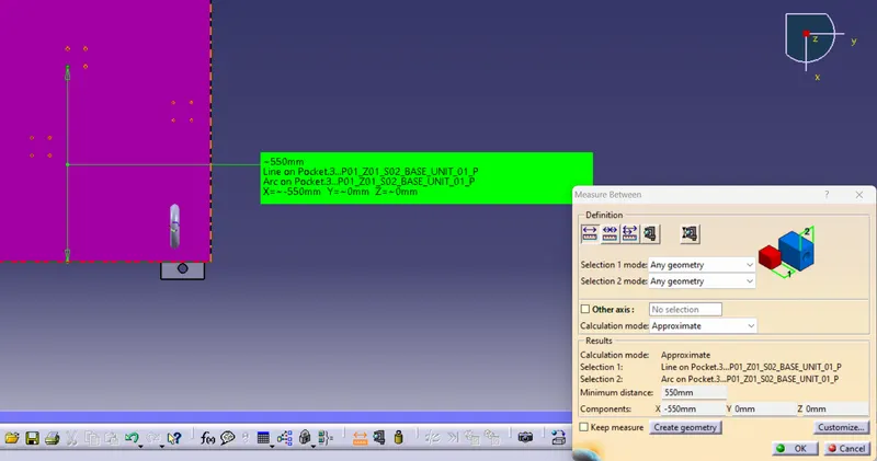
The measuring hole is drilled over the base plate which having exact cordinates and acts as reference for the
other holes. Due to irregular shape of the car panel the holes coordinates are not
nominal like 250.0, 310.0 But it like 250.62,310.84. These holes are covered by using some plate to protect
against dust, damage etc.
VI) Eyebolt :-
Eye bolts used as a connection point for rigging, anchoring, pulling, pushing, or hoisting applications.
Although eye bolts are commonly used in BIW applications.
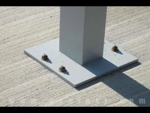
VI) Floor Plate :-
Floor plate is simple plate which holds the legs of BIW fixture to floor surface.
The base plate acts as an interface between the BIW fixture and the foundation, completing the load path into the floor.
Base plates help provide a uniform distribution of superstructure loads to the foundation
VII)Weld bar :-
A weld bar in a BIW fixture is a metal rod or bar that is used to hold the car body parts in place during the welding
process. The weld bar is usually attached to the fixture's base plate and is positioned to align with the joint
between two metal parts that need to be welded together
* Weld bars are used after the levelling is done by levelling screw.
*Weldbars are steel plates along the sides of the base plate of a pedestal.
*Weld bars are used to position the positions permanently.
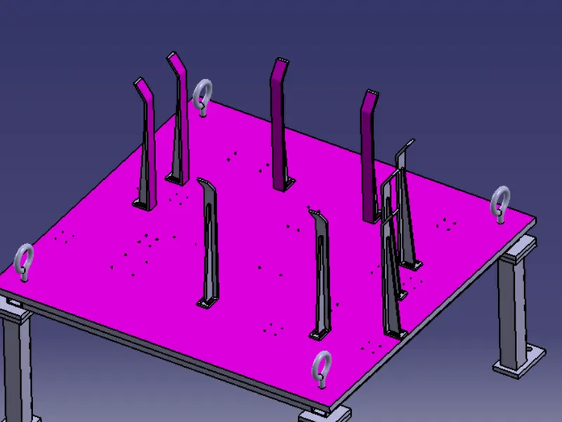
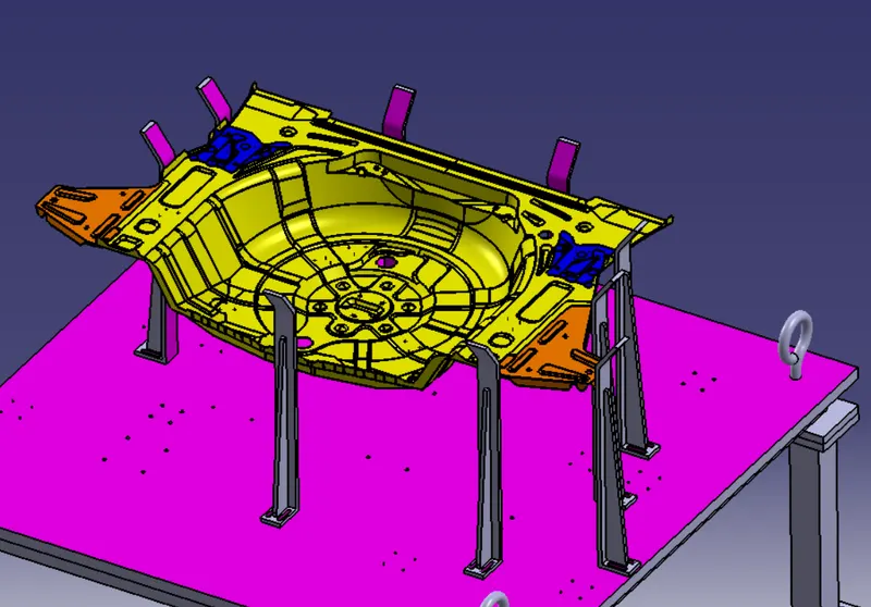
Rough Locators & what is their uses -
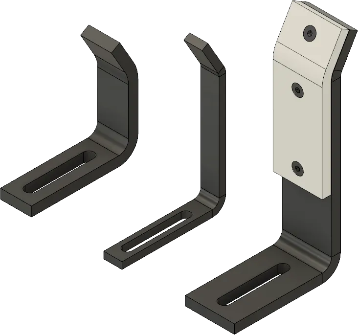
In BIW fixture design, rough locators are temporary fixtures that are used to locate and hold the body components
in place during the assembly process. They are called "rough locators" because they provide a general positioning
of the body components, but do not provide the precise alignment and orientation required for final assembly.
Rough locators are typically made from inexpensive and easily machinable materials such as wood, plastic,
or soft metal. They are designed to be easily and quickly fabricated and installed, allowing for rapid assembly o
f the body components.
The use of rough locators is beneficial in several ways:
a) Cost-effective: Rough locators are inexpensive to produce, which makes them an affordable option for temporary
fixtures in the assembly process.
b) Rapid assembly: Rough locators can be quickly installed and removed, allowing for fast and efficient assembly
of the body components.
c) Adjustable: Rough locators can be easily adjusted or modified to accommodate variations in the body
components or assembly process.
d) Reduced risk of damage: The use of rough locators reduces the risk of damage to the body components
during the assembly process, as they provide a temporary and less rigid hold compared to the final fixtures.
Overall, the use of rough locators in BIW fixture design can help to improve the efficiency and accuracy of the
assembly process while reducing the overall cost of fixture design and manufacturing. However, it is important to
note that rough locators are not suitable for final assembly and must be replaced with more precise fixtures before
the final assembly process.
Designing considartion of a Rough locators -
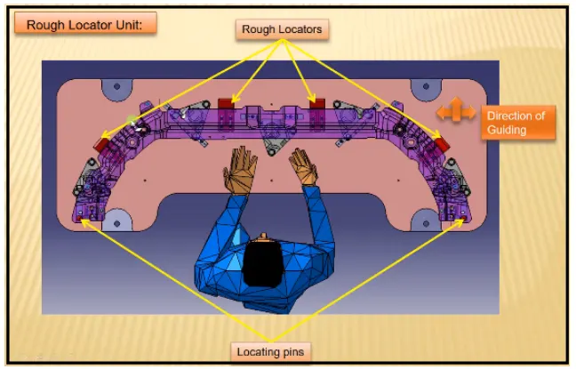
When designing a rough locator in BIW fixture design, there are several key points that should be considered to
ensure that the rough locator is effective and meets the desired specifications.
Some of these key points include:
a) Material selection: The material used for the rough locator should be easy to machine,
inexpensive, and able to withstand the forces applied during the assembly process. Common materials used for
rough locators include wood, plastic, or soft metals such as aluminum.
b) Part positioning: The rough locator should be designed to hold the body components in the correct position and
orientation during assembly. Rough locator has to be placed in the same angle of the car part edge with minimum
distance of 2.5 mm from the edge of car part, so it should no damage panel.
c) Accessibility: The rough locator should be designed for easy installation and removal during the assembly process.
This can include features such as slots or holes for fasteners or handles for easy handling.
d) Flexibility: The rough locator should be designed with some degree of flexibility or adjustability to accommodate
any variations in the body components or assembly process.
e) Rough locator : should be designed with entry angle for the car panel. Generally it ranges between 30-45 degree.
By considering these key points, designers can ensure that the rough locator is effective, efficient, and meets the
desired specifications for the BIW fixture design. It is important to note that rough locators are temporary fixtures and
should be replaced with final fixtures before the final assembly process.
Gun study process -
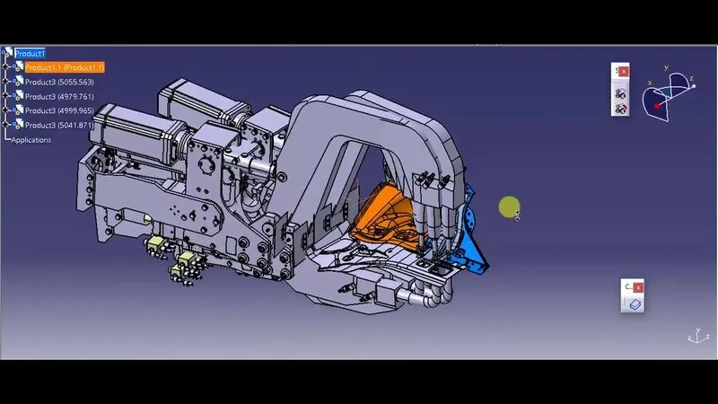
In BIW (Body in White) manufacturing, the gun study process is a simulation technique used to analyze the performance
of automated welding guns. The gun study process is a critical step in ensuring the quality of the welds in the final product
and involves the following steps:
a) Gun selection: The appropriate welding gun is selected based on the type of joint, material thickness, and other
relevant factors.
b) Gun calibration: The welding gun is calibrated to ensure that it is operating within the specified parameters for voltage,
amperage, and wire feed speed.
c) Gun path programming: The welding gun path is programmed to ensure that it follows the correct path along the joint
and maintains the correct orientation and distance from the joint.
d) Virtual simulation: A virtual simulation is performed using software to simulate the welding process and analyze the
performance of the welding gun. The simulation helps to identify any potential issues or problems with the gun path or
welding parameters.
e) Validation: The optimized welding parameters and gun path are validated through actual welding tests to ensure that
the weld quality meets the desired specifications.
The gun study process is critical for ensuring the quality of the welds in BIW manufacturing. By performing a virtual
simulation of the welding process and optimizing the welding parameters and gun path, manufacturers can ensure that
the welds are strong, consistent, and meet the desired specifications for the final product.
Points need to consider during the gun study -
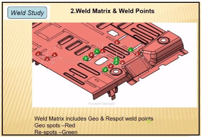
During the gun study process in BIW (Body in White) manufacturing, there are several key points that should be considered
to ensure that the welding process is optimized and the weld quality meets the desired specifications. Some of these key
points include:
a) Joint design: The joint design should be carefully considered to ensure that it is appropriate for the material, thickness,
and type of welding process being used.
b) Welding parameters: The welding parameters, including voltage, amperage, and wire feed speed, should be optimized
to ensure that the welds are strong and consistent.
c) Gun path programming: The welding gun path should be programmed to ensure that it follows the correct path
along the joint and maintains the correct orientation and distance from the joint.
d) Weld bead size and shape: The size and shape of the weld bead should be carefully considered to ensure that it is
appropriate for the joint design and welding process being used.
e) Material preparation: The material should be properly prepared prior to welding to ensure that it is clean and free from
any contaminants that could affect the quality of the welds.
f) Cooling time: The cooling time between welds should be carefully considered to ensure that the welds cool sufficiently
and are not subjected to excessive heat, which could affect their strength and consistency.
g) Weld quality testing: The welds should be tested for quality using non-destructive testing techniques such as ultrasonic
testing, X-ray testing, or visual inspection to ensure that they meet the desired specifications.
By considering these key points during the gun study process, manufacturers can ensure that the welding process is
optimized and the weld quality meets the desired specifications for the final product. This helps to ensure that the final
product is strong, durable, and safe.
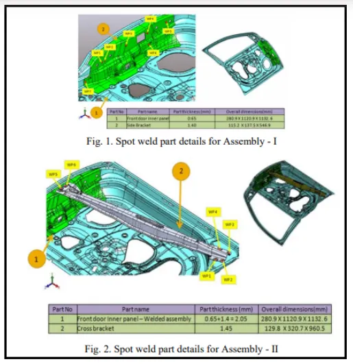
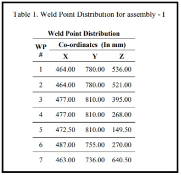
Table 1 with respect to the body line of car.
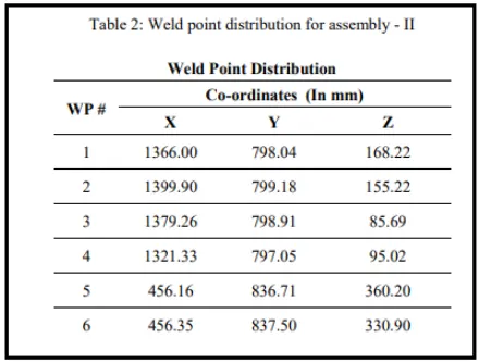
The weld spot locations with respect to the body line of car are as shown in Table 2.
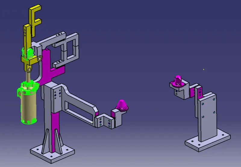
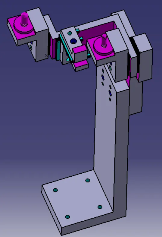
Pin, Clamp unit and Rest unit :-
Pin Unit - there is mainy two tupes of pin units one is fix type pin unit and another one is retractable type pin unit.
in detail mentioned below.
Fix pin unit -
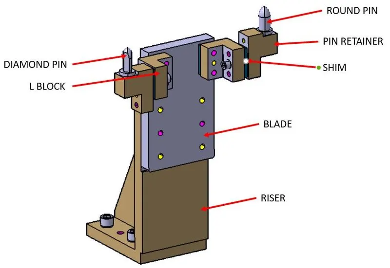
An assembly of standard and manufacturing parts consisting location pin is called Pin unit. A pin unit in which pin’s position
is fix, is called Fixed Pin Unit. Pin unit is used to lock the rotational position of panel. Round Pin is used to control panel in
two directions while Diamond Pin is used to control panel in one direction.
Retractable Pin Unit
Inline Retractable Pin unit consist one Pin cylinder which operates the pin in one direction. In this unit Pin is directly mounted
on the cylinder and it is must to have pin and cylinder inline with the hole or slot of the panel. Pin cylinder is controlled in
two directions with the help of shimming. Below picture is an example of inline retractable pin cylinder.
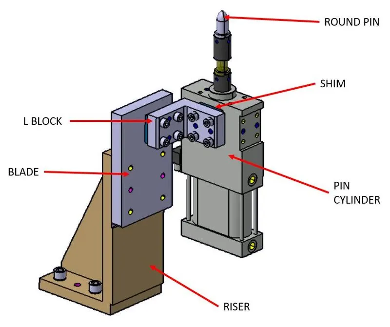
Clamp unit - A Clamp is a device that is used to hold the part tightly, yet, firmly in the assembly, The clamp prevents any sought
of movement of the assembly in the fixture and ensures proper operation on the part without any distortion.
The clamp must be placed in such a way that it does not interpret the operation.
The clamp plan is the data provided by the customer. The clamp plan provides information on the location of pins,
rest units, Clamp units, Dumps, etc.
1) It gives the details of the exact position of the clamping locations in form of coordinates.
2) The clamp position in some cases will be in such a way that it might damage the tool, or very near to pin position.
3) In such cases, We should not take the decision to change the clamp plan without discussing it with the customer.
Fundamentls of design :-
3-2-1 principle: Our ultimate intention for using pin unit is to fix the work piece so that it does not deviate from
the position while the operation is being performed on it. For this reason we use 3-2-1 principle.
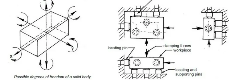
Every component we know has 6 degrees of freedom. They are listed below:
- Translational motion along x-axis.
- Translational motion along y-axis.
- Translational motion along z-axis.
- Rotational motion along x-axis.
- Rotational motion along y-axis.
- Rotational motion along y-axis..
In 3-2-1 principle we make use of locating pins in the given order to fix it on a fixture:
1) 3 pins are located on the bottom side of the component. These pins constrain the translational motion of the body in
z direction and rotational motion along x-axis and y-axis. Thus 3 degrees are restricted. But the body still can rotate
along z-axis and translate in x-axis and y-axis.
2) 2 pins are located on the back side of the component. These pins constrain the translational motion along x-axis and
rotational motion along z-axis. Thus we have constrained 5 degrees in total. But translation along y-axis is still possible.
3) 1 pin located on the adjacent side of the 2 pins we can constrain the last degree that is translation along y-axis.
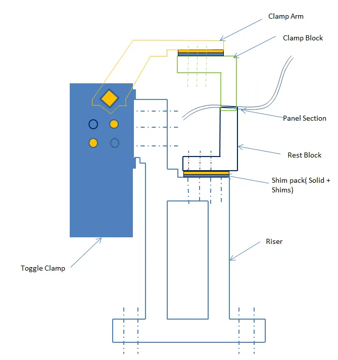
Parts of a clamp unita and rest units are as follows
Colour Code -
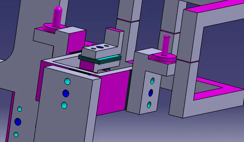
Blue - Dowel holes.
Dark Blue - Bolting holes.
Pink - machining Surface.
Base Unit -
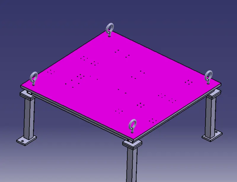
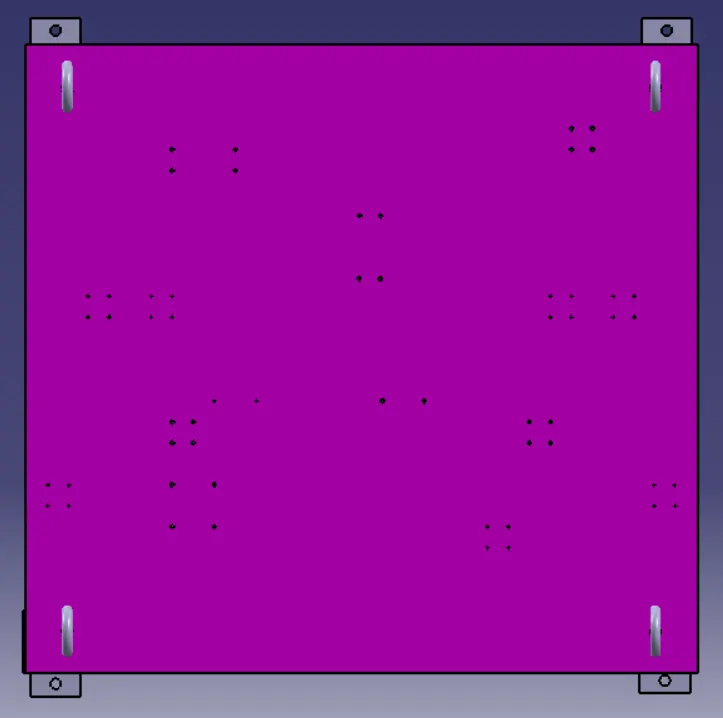
Hole Nominality -
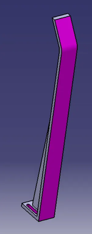
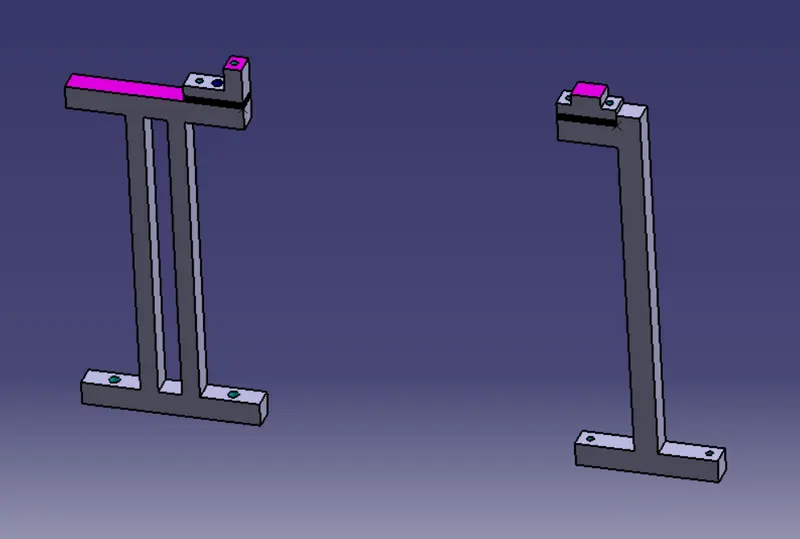
Rough Locators -
Pin Unit
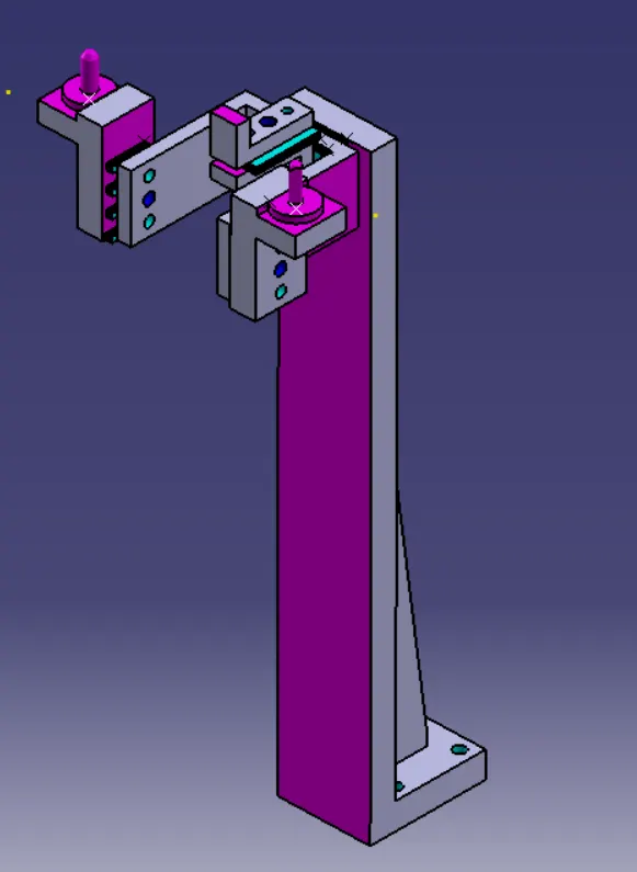
Clamp Unit -
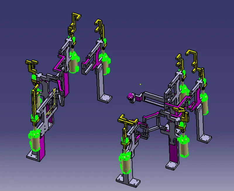
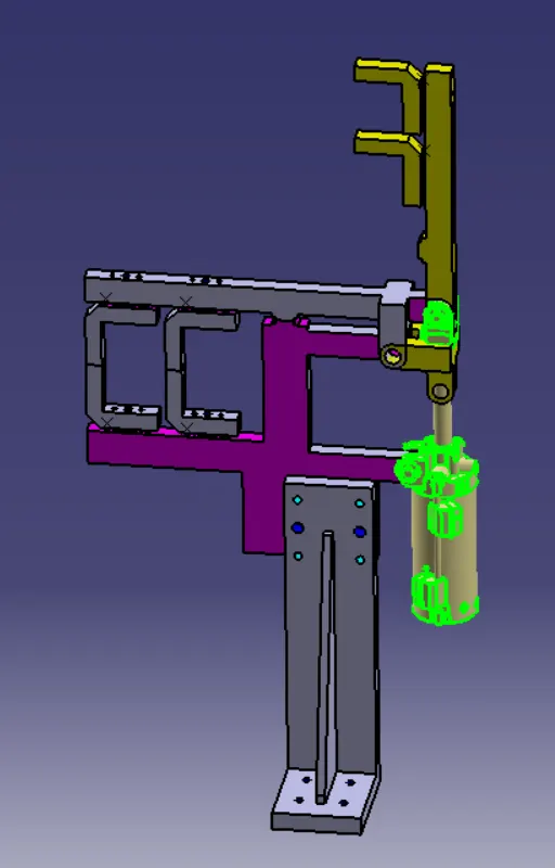
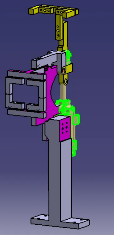
Rest unit -
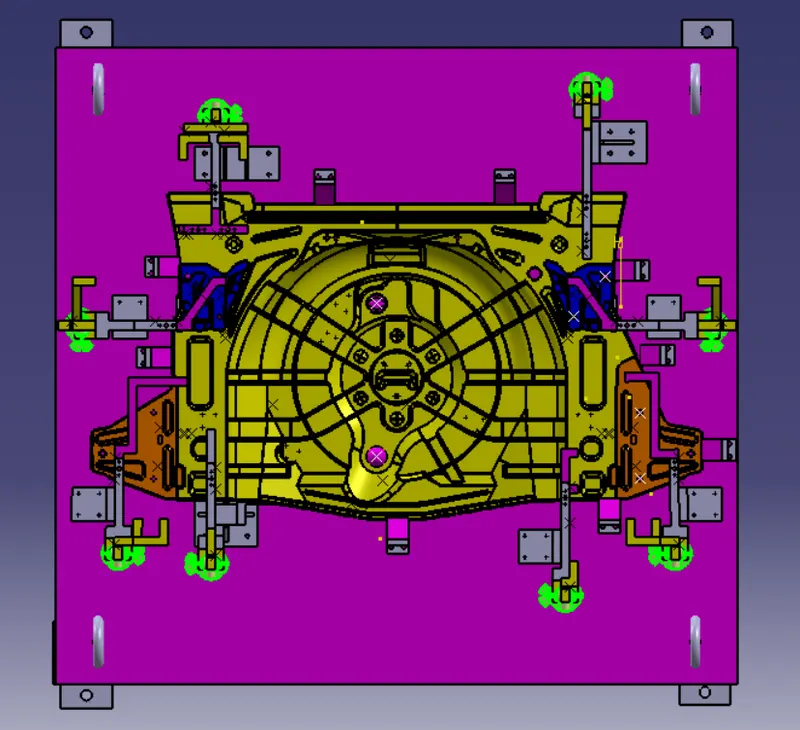
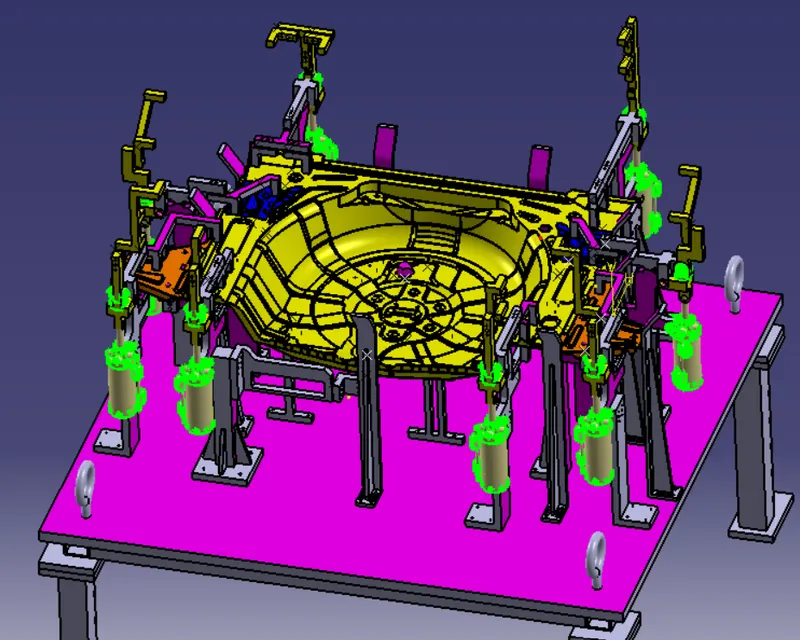
Assembly -
CONCLUSION -
Hence, 3D finishing is performed on the designed Assembly of Fixtures and Rough Locators were designed for the
given panel.