Week 8:- 3D Finishing Challenge 2
AIM:
- Perform 3D finish for all units of Assembly design.
- Create Rough locators for Assembly.
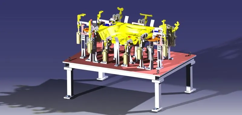
3D-FINISHING:
3d Finish is a process where the design is being completely finish and to be ready for final simulation and 2d detailing.
- While finishing the design the nominality is checked which ensures the easy assembly of all the units.
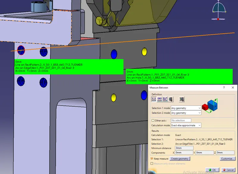
- The hole concentricity and holes sizes are checked which ensures the assembly of different parts.
- The gaps between the different units are checked to ensure the proper individual working of different units.
- Design the rough locators, which helps to loading a panel in correction orientation.
- Design the pneumatic lay outing for pneumatic connection.
- Gun study is major and most important part in 3d finishing.
- Selection of sensors, Solenoid valves as per the requirement and implementing in design.
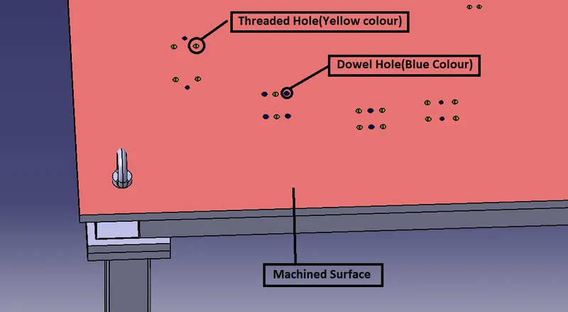
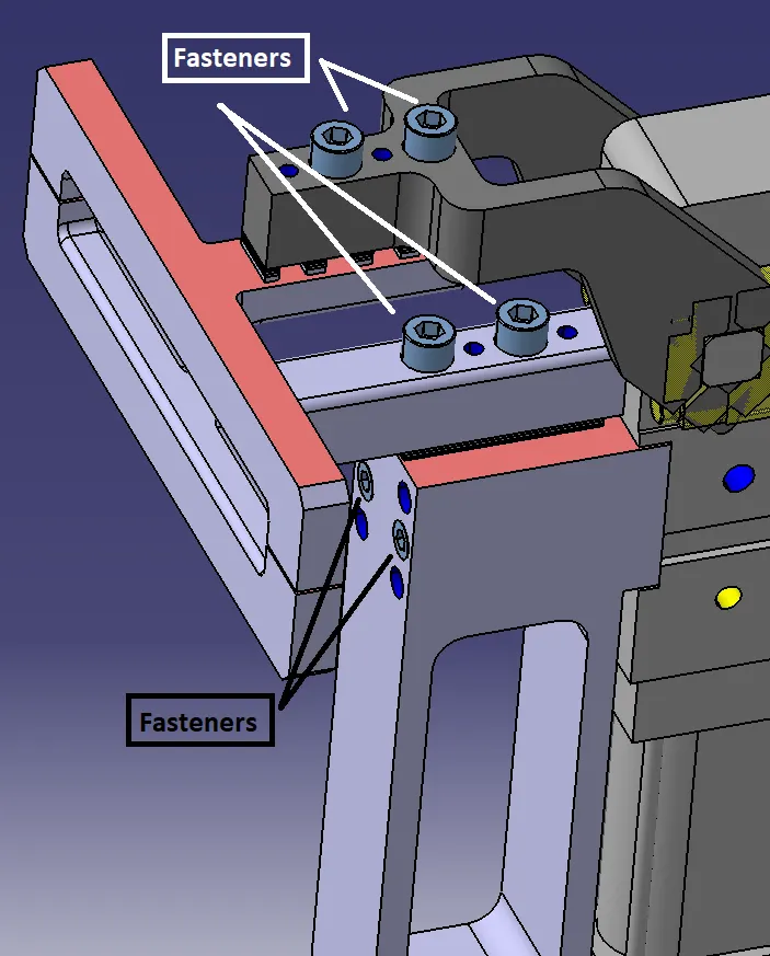
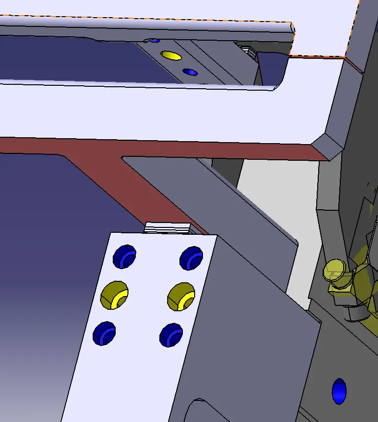
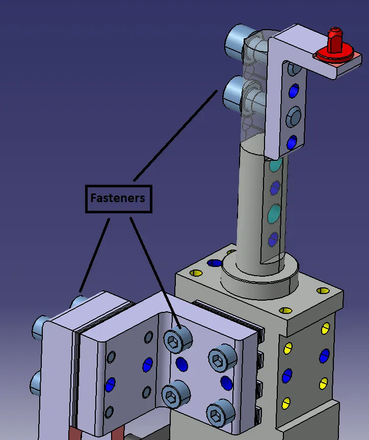
- Fasteners are implemented as per the hole size and the standard colour codes as per the customer requirement are applied to differentiate the type of hole whether its dowel hole, Threaded hole or clearance hole.
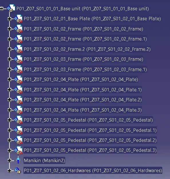
- Renaming of the assembly and the part is done to give every part a different identity so everyone can identify in which assembly this part is going to be fit.
- After doing all these things the model is sent for simulation and 2d detailing.
Points Need to Be Taken Care of While Finishing the Design:
The following are the points taken into consideration while finishing the design.
- Hole Concentricity and Hole Sizes:
All part holes concentricity and hole sizes are checked for easy assembly while finishing the parts.
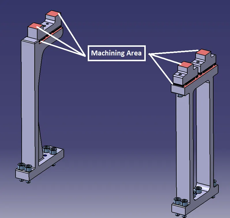
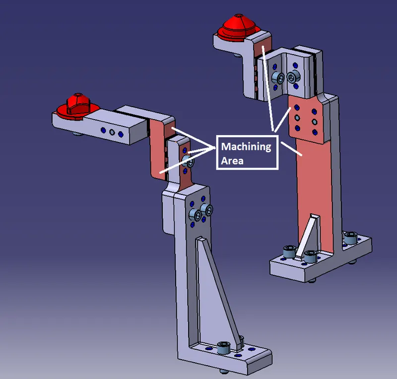
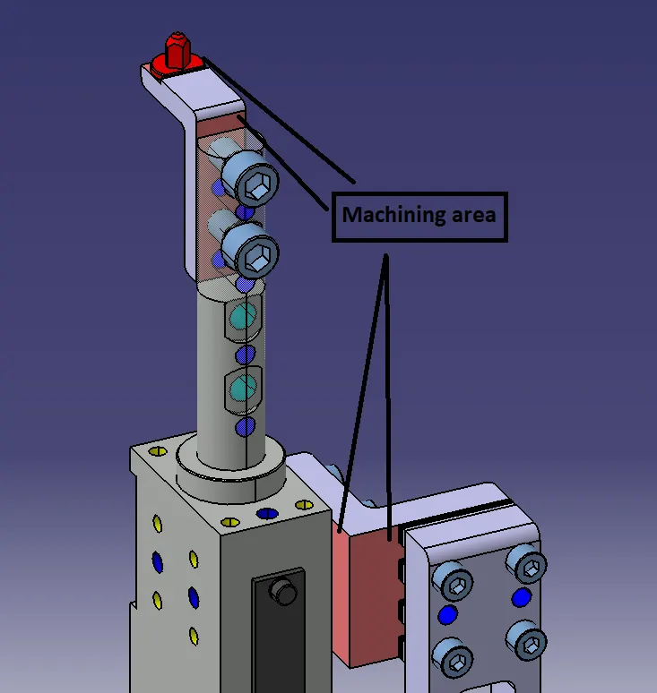
- Machining Area:
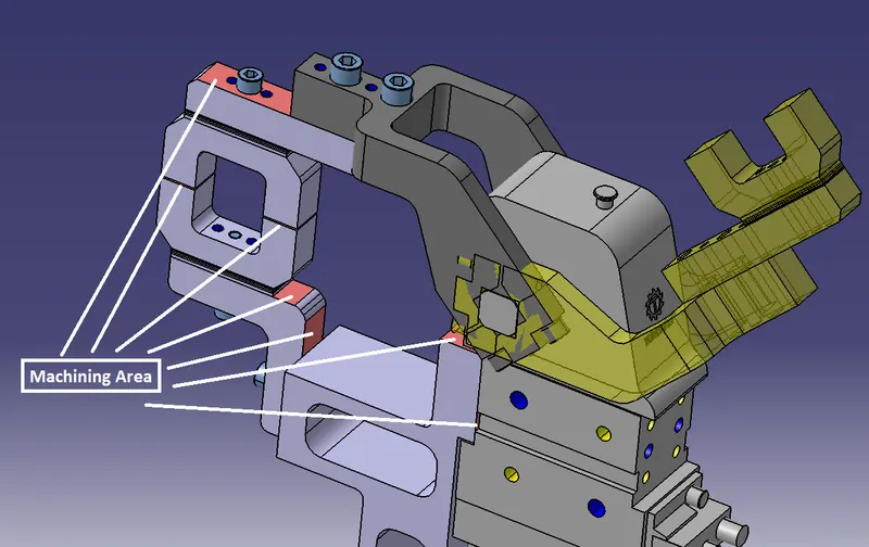
The machining area in every part should be defined and the machining area should be highlighted by using standard colour code. Machining is to be done on parts to properly Mount with mating parts. Machining only on desired faces reduces cost and save time. And also Machining increases accuracy of dimension. So before going to simulation or detailing machining area should be defined.
- Nominality:
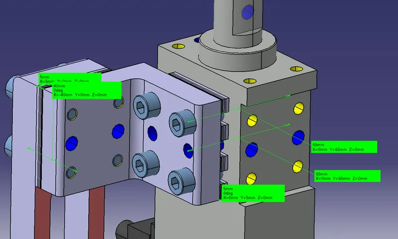
All unit’s dimension should be maintained nominal to facilitate easy assembly of the unit.
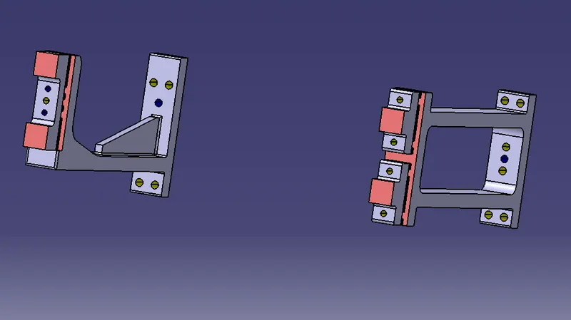
- Holes Colouring Standard:
In a 3D finish hole colouring should be done because it helps to identify what type of hole it is. It depends on customer standards. Customer specific colour like:
Dowel hole should be given blue colour.
Threaded hole should be coloured with yellow.
Counter bore, open hole should be given cyan blue colour.
- Pneumatic Lay outing:
Pneumatic lay outing is collection of different pneumatic pipes which work as a inlet to the pneumatic cylinder. It should be done properly for proper functioning of the units.
- Gaps Checking:
The gaps between the different units are checked to ensure the proper individual working of different units.
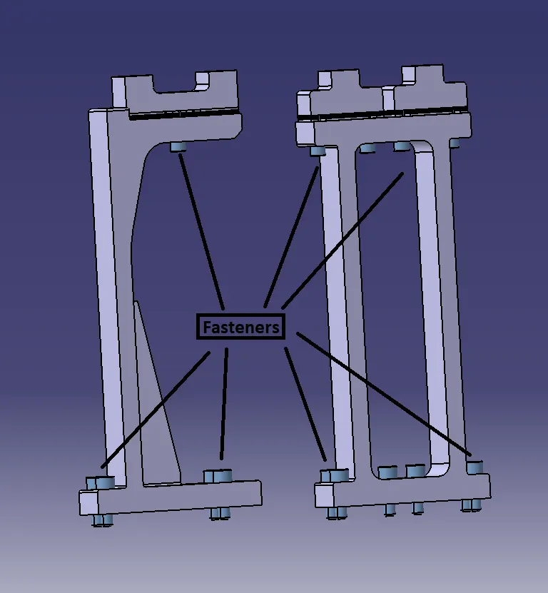
- Fasteners Implementation:
Fast should be implemented in all the units as per the requirement and load on the part.
- Avoiding Clash Between Different Parts:
Proper gap should be maintained between units to avoid the clashes between the different units.
- Mylar Splitting as Per Panel Profile:
Mylar splitting as for panel profile should be confirmed while finishing the design.
- Proper Renaming of Parts or Assemblies as Per the Standards:
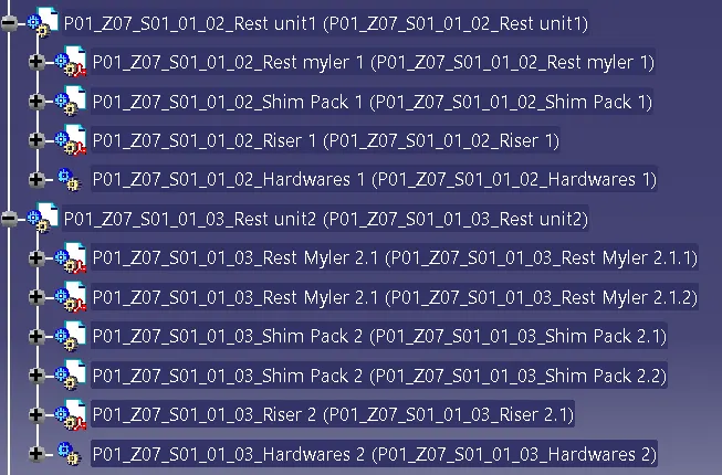
Proper renaming of parts and assembly should be done while finishing the design and hence we can identify each and every part easily with Unique Identification.
ROUGH LOCATORS:
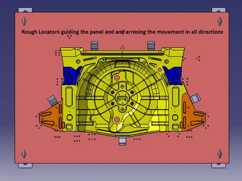
- A rough locator is a part designed to guide the panel, to locate the car panel on to the pins accordingly. A rough locator can be of standard part or a make part.
- Rough locators also work as Poka yoke. Poka yoke is a Japanese concept used for mistake proofing.
- Rough locators are also used to help to locate the work pieces in the automation process. Locating refers to the desired location where you want the workpiece to be when it is getting worked on either by a person or a team or a robot.
- The accuracy of the locating components directly affects the consistency and how the final product will come out. This is why these components are essential to our setup.
- It can be also called as fool proofing method. Because without rough locator the part cannot be loaded in correct position.
- The rough locators are set accordingly to the angle of the respective panel and hence the part can be loaded in a defined direction and orientation only.
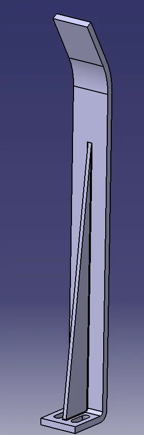
Points Needed to Consider While Designing A Rough Locator:
The following are the points needed to be considered while designing the rough locator.
- Rough locator should be placed at the edges of the car panel, which it has to guide.
- Applicator has to be placed in the same angle of the car part edge with a minimum distance of 2-5 mm from the edge of the car part.
- Prof locator should guide the panel in pin arresting direction.
- Rough locator should start guiding the panel before 10 to 15mm to the start of the pin engagement.
- Applicator should be designed with entry angle for the car panel. Generally, it ranges between 30-45 degree.
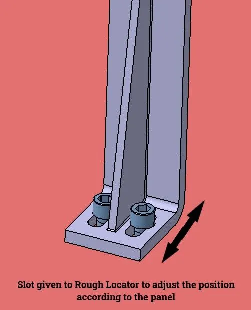
- Rough locator should be designed with two slots to mount the easy adjustment.
- The slot should be in the direction of car part guiding.
GUN STUDY:
Welding is predominantly used in automobile industries and requirements for fixtures that ease the welding process is a continuous development task in any industry. Car Body-In-White (BIW) is a complicated steel-structure including 300~500 sheets with complex shape and are assembled by means of welding in a high rhythm through 55~75 robotic work-stations. The foremost step taken before starting the design of welding fixture is to arrive at the spot weld locations. The location and orientation of other critical units of the fixture including clamps, locators etc., are decided based on the weld spot distribution. The weld spots for Front door inner panel Side bracket assembly are located as shown in Table 1 with respect to the body line of car. It includes the study of the weld gun (A portable device for semiautomatic welding of parts of various articles) which is going to be used for the operation depending on the size of the part, Thickness of the part etc. It includes the study of the weld matrix & the weld point positions. There are two types in weld point one is geo weld points which ensures the geometry of the assembly & second is the Re spot weld points which adds strength to the already welded part.
The device used to make spot welding on the panel is called Gun. The Gun may differ depending upon the application. Fixtures will be designed by considering the weld spots on the panel. After designing the Fixture, the CAD file of the gun be placed on the weld spots to check whether the Gun is clearances with the Fixture. After adjusting the Fixtures, the coordinates of the welds be taken for further operations of Weld Gun.
Points needed to consider during gun study:
Weld gun study is very time-consuming process, the entire welding cycle time study depends on the no. of spots & weld gun study.
Following are the points need to consider during gun study.
- The axis of weld spot along welding direction must be normal to the weld surface.
- The no. of weld spots for the panel, the time required to spot each weld & the total time required to complete all weld spots.
- If we have one or more device models & we want to program, the behaviour of each model in the work cell can be simulated over time. Instructions for each device are coded by giving sequences. The sequence defines the motion, manipulation & action of the devices. Based on the distance of each tag point from home position, motion type, speed & acceleration one can obtain cycle time for each device assigned with sequences. This way robot cycle time is precisely calculated.
- After sequencing all the devices, a simulation is run with “collision check” ON & made sure that the welding operation is collision free.
FIXTURE ASSEMBLY:
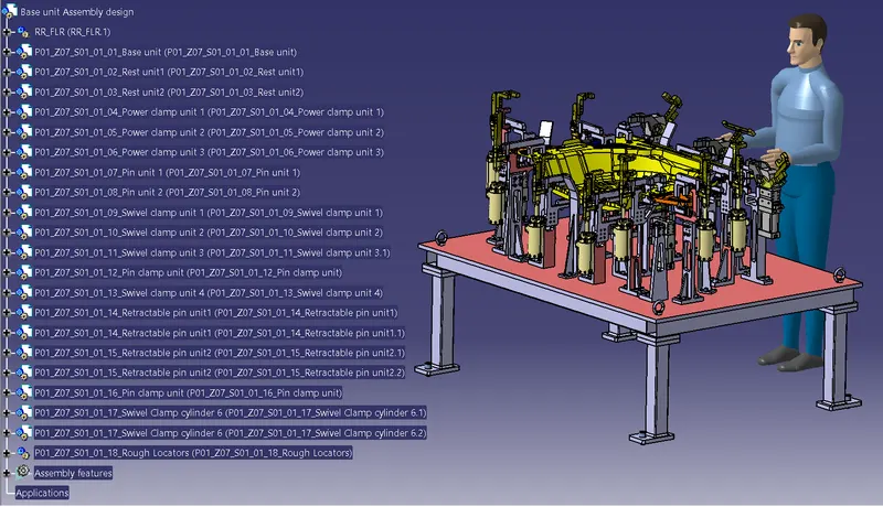
Renaming and structuring of the design tree:
Renaming of the design tree is done. and structuring design tree in way that its simple to identify the units. some units use multiple time those are easy to identify by its name.
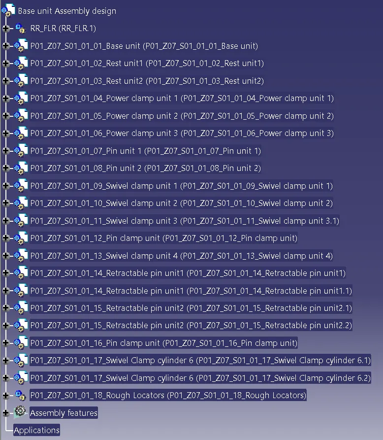
BASE UNIT:
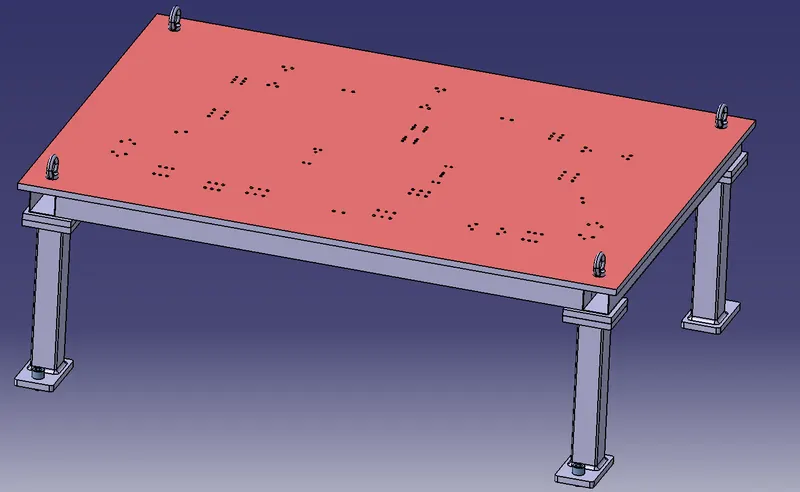
A base unit is the unit designed to mount all the other units of the tool,also other parts necessary for a tool like pneumatic valve box,trunking cable path will also be mounted on to a base unit.
Below are the some parts of a base unit in general.
- Trunking channel
- Base plate
- Valve box
- Measuring hole cover
- Eye bolt.
- Pedestal.
- Weld bars.
- Floor plate.
Typical Parts of a base unit:
The typical Parts of a base unit are:
Base Unit:
Base Plate is a machined plate of 25 to 40mm thickness made of steel and aluminium on to which the holes are drilled to mount the individuals units like clamp units.pin units etc of a tool.
There are three key benefits to a Base plate:
- They can help to quickly and accurately tram in fixtures and vises.
- They can hold large, complicated, or odd-shaped parts.
- They protect the cast iron machine table.
Pedestal:
A pedestal is a part which connects the base plate to the floor plate.A pedestal is a standard part in general,and in some cases it can be a welded frame integrated with the base plate.
A standard pedestal can be of different heights and different sizes.
Depending on the size of the base plate,the number of pedestal varies for load distribution.
A pedestal are of different types with different inclinations.
Trunking Channel:
Trunking channel is a standard part which will accommodate all the pneumatic and electrical hoses and wires for the units.The trunking channel include all the pressure inlet cables going to the pneumatic parts of the fixture and protects them from damaging while operation is in process.
Valve Box:
Valve Box is a standard part which will contain all the valves for the pneumatic units.The valve box is the box which includes different solenoid valves.The pneumatic fixtures work on air pressure provided to it.So the arrangement of air pressure inlet and outlet is done within this valve box.The trunking channel includes all the pressure inlet cables going to the pneumatic parts of the fixture and protects them from damaging while operation is in process.
Eye Bolt:
An eye bolt is a bolt with a loop at one end. They are used to firmly attach a securing eye to a structure, so that ropes or cables may then be tied to it.
Machinery eye bolts are fully threaded and may have a collar, making them suitable for use with angular loads up to 450. Eye bolts without a shoulder should not be used for angular loads.Heavy forged eye bolts with a continuous eye may be forged with an integral shoulder, allowing their use for heavy off-axis loads.
These are used for the transporting of the tool by inserting hooks into them.Some, hooks or fork lift holes are also provided in some cases for transporting purposes.
Floor Plate:
Floor plate are grouted to the floor with fixed bolt on the ground.These are also called as foundation plates.
There will be a clearance of 10mm maintained between the pedestal base plate and the floor plate.
This clearance will be used by the leveling screws,for leveling the entire tool.
Weld bars are to be used to weld the positions permanently after leveling is done.
A weld bar is a plate along the sides of the base plate of the pedestal.
Fundamentals Of a Base Plate Design:
The fundamentals of a base plate design are:
- As designer it is important to know how big base plate or bigger base welded structure will be handled during the fabrication & handling process. Special care needs to take care of flatness if the base size is very long.
- A base plate size should cover all the units with its outer periphery including opening.
- A base plate is preferred to be designed with respect to BCS coordinates.
- A base plate should be drilled with datum holes / measuring holes in line with a pitch of 1000 mm in general.
- Number of datum holes is depends on the size of the base plate.
- Datum holes should be drilled at nominal values of coordinates, & in terms of 50 x 100. (In general) ex. X=100, Y 600, Z-250.
- Datum holes should be drilled with dia 100 mm away from other units.
- Datum holes should be covered with cover plates.
- Depending upon the weight, eye bolt size is selected for lifting holes on base plate Generally, 4 eye bolt provision is made You also need to select the location of eye bolt considering the rope/ belts used while shifting the structure or complete fixture are not damaging any units (rest, clamp or location units) nearby.
- Depending upon the component size & weight of the total units you can decide whether you need a fabricated base or just plate. Mostly fabricated bases are used made of square or rectangular tube with the plate.
- Most of the OEM makes 4 dowel holes at 4 corners & put small aluminum plate marking X Y&Z coordinates of dowel holes. If the base length is too long few OEM' s follow the methodology of having holes at 500 mm distance.
- The best unit of the fixture must be strong enough so that deflection of the fixture is as minimum as possible. This deflection of a fixture is called because of forces of welding, clamping of the work piece.
- The base unit of the fixture should have the mass to prevent vibration & chatter.
- The base unit may be built from simple sections so that other units may be fastened with screw or Welded necessary. Those parts of the fixture that remain permanently with the fixture may be welded. Those parts that need frequent changing may be held with screws .
- The base unit should be parallel to the floor to adjust this there should be provision of the height adjusting mechanism.
Renaming of parts list in base unit:
Colour Coding given to the holes on the base plate:
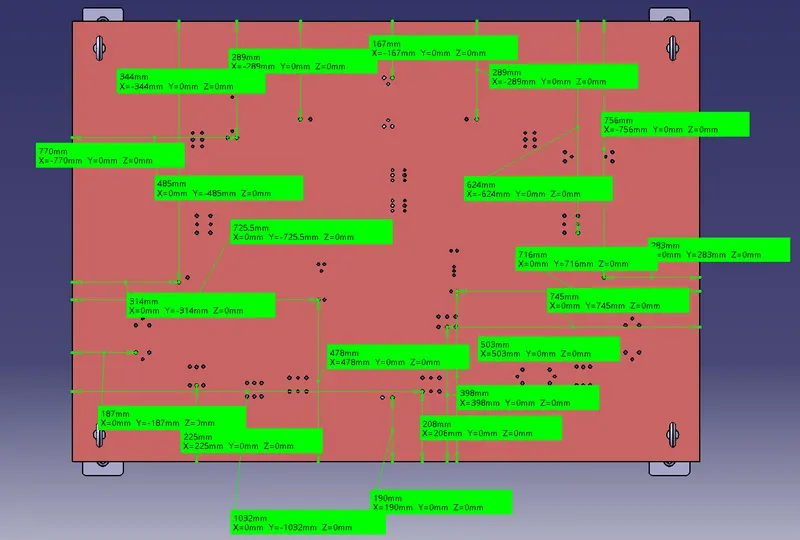
- Threaded hole and dowel holes making nominal and colour-coding are done so easy to distinguish holes.
- Threaded hole (Yellow), clearance hole (Sky blue), Dowel Hole(Blue), Machining surface(orange).
Positioning of rough Locators on the Base Plate:
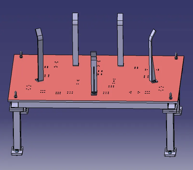
Holes made nominal to the base Plate:
|
Checking Parameter |
Action |
|
Rename of the design tree |
Done |
|
Mark Machining Area |
Done |
|
Nominality |
Done |
|
Holes colouring standard |
Done |
REST UNIT:
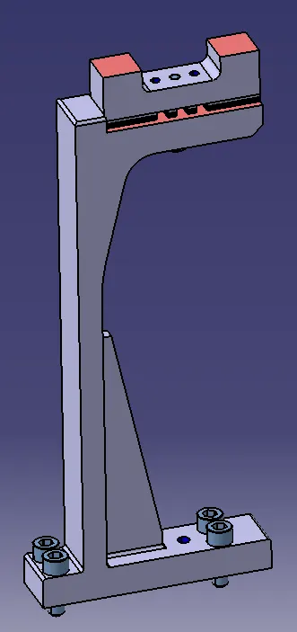
Rest unit is unit designed to support car panel using Mylar/ NC block/ rest component is rested only, no upper clamp or force applied there. It is the simplest unit to design because it has fewer parts to design & the purpose is only resting of the car panel.
Because of the simplicity the rest unit is combined with other unit to reduce the cost of the overall project.
It can be combined with clamp unit to clamp as well as to rest the car panel. It can be combined with locating unit to locate as well as to rest the car panel. Also locating, clamping & Test unit can be combined together in one unit to reduce cost.
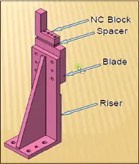
There is no cylinder attached to it. It has rest Mylar, blade and riser & below is different parts of rest unit. Rest unit is also divided into simple support unit, multiple support units & retractable support unit.
Marking of Machining area:
Fasteners Implementation:
Colouring Standards:
Proper Renaming of Parts:
|
Checking Parameter |
Action |
|
Rename of the design tree |
Done |
|
Mark Machining Area |
Marked |
|
Nominality |
Done |
|
Holes colouring standard |
Done |
|
Fasteners Implementation |
Done |
POWER CLAMP UNIT:
A clamp unit is a unit designed to clamp/hold the car panel with NC blocks/Mylars/rest by using a pneumatic cylinder. Clamp arm, finger, Rest/backup, L-block, shims, riser, pneumatic cylinders are the typical parts of clamp unit. Clamping force should be considered while designing clamp unit. Usually clamp open position is 90o.Fingers are attached to clamp Mylar. In Clamp unit shim to one side is more enough because it will restrict translation motion in upward direction and downward direction only. There is another type of clamp unit known as swivel type. There is pivot pin around which clamp arm rotate.
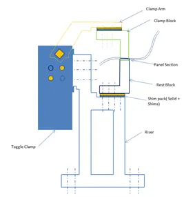
Clamping Guidelines:
Locating the work piece is the first basic function of a jig or fixture. Once located, the work piece must also be held to prevent movement during the operational cycle. The process of holding the position of the work piece in the jig or fixture is called clamping. The primary devices used for holding a work piece are clamps. To perform properly, both the clamping devices and their location on the work holder must be carefully selected.
Factors in Selecting Clamps:
Clamps serve two primary functions.
- They must hold the work piece against its locators.
- The clamps must prevent movement of the work piece.
Procedure of Clamping the work piece to the Panel:
- Place the work piece, supply air at clamp side without installing clamping block, operate the clamp arm to the end of clamp.
- Under the above conditions, adjust shim so that the space between the work piece and the clamping block is about 0.5 mm. Theoretically there is no clamping force for holding a work piece under this condition.
- In order to generate clamping force from the state described in step B, insert additional shim. The thickness of the shim differs depending on the arm length and pressure, so please refer to the graph on front matter 3 as a guide. About 10% error may occur due to the difference in tolerance of the clamp cylinder body.
Considerations to be taken while designing a rest unit or a clamp unit:
Considerations to be taken while designing a Rest Unit or a Clamp unit are:
1.Study of process planning document:
Process document should contain following information, which are necessary to design clamp unit.
- No of sheet metal panels to be welded.
- Total no of spots.
- Welding gun details if it is already recommended by process engineer study it in details like shape and its type.
- Study the PLP (Principle Location Points) data along with the nearby spot data.
2.CAD Software:
If you are using any specific CAD software as per the customer requirement e.g., CATIA understand the customer guidelines how to create the fixture, unit, weldment and base fabrication. Once you have understanding of CAD software methodology to be followed for design of single part, Unit assembly and base then start the design by adding the panel assembly in your fixture or unit assembly.
3.Height Selection:
Take an overview of the working height if we have manual welding. For robotic welding also its important to see the working height in consideration of the robotic gun, turn table height if manual loading is done.
4.Gun Placement:
Put the proper gun at the spot location. Do the proper gun study and place the gun as per the GEO or re-spot decision and operator approach. Once basic gun is placed considering the throat depth and throat gap start building the clamp and rest block at the PLP.
5.Panel section creation:
Take a section at PLP either in clamp opening direction or normal direction. Sections should be normal to base. Panel section through X, Y or Z direction passing through PL. Section will help in finalizing the shape of clamp and rest block. Most importantly used for finalization of gun shape.
6.Finalization of a base plate:
Consider following things before deciding the base plate.
- Height of maximum and minimum weld spot from the floor.
- No gun arm should touch the base plate.
- Operator ergonomic while accessing all the spots.
7.Construction of Rest and Clamp Block:
If standard Mylar has to be used then select the proper blank size as per the requirement consider 0.5 mm above the panel.
8.Clamp cylinder selection:
Select the clamping cylinder as per the pivot point distance from the PLP. You may choose various cylinder 50 Dia, 63Dia, 80 Dia.as per the requirement.
9.Clamp and Rest block creation:
Create clamp or rest block as per the company guidelines.
Many companies have size of clamp block as 20x20 mm and no of mounting screws and dowels. Many use 20x20 size rest or clamp block with one screw and 2 dowels or few uses with 2 screw and 2 dowels. Materials of clamp block and rest block to be decided as per the A class panel or B class. Most of exterior panel holding Teflon material is used. Otherwise, steel is used with heat treatment. Sometimes Aluminium blocks are also used. Start construction of mounting plate or fabrication structure as per the company standard to make the connection with the base plate.
10.Riser:
As per OEM, Tier 1 standard use the different standards mounting risers. Do not forgot to add the 5 mm shim.
11.Rough Locator or position sensor mounted on clamp unit:
If you are combining rough locator or part sensor bracket along with the clamp unit. Take necessary care means distance of rough locator from panel.
12.Hardware:
Add all the hardware screws, dowels and washer as per the size.
13.Clamp Open Position:
Check all the clamp open, gun open position and ensure that there is fouling with panels or any other surrounding units.
Fasteners Implementation:
Checking the Hole Concentricity:
Colouring Holes as per the Standards:
Yellow - Threaded Holes
Blue - Dowel Holes
Indicating the Machining Area:
Mylars Splitting as per the Panel Profile:
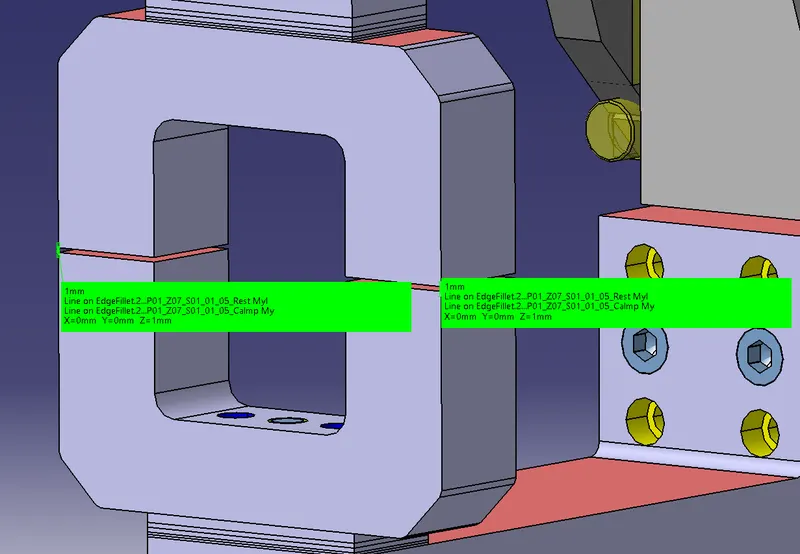
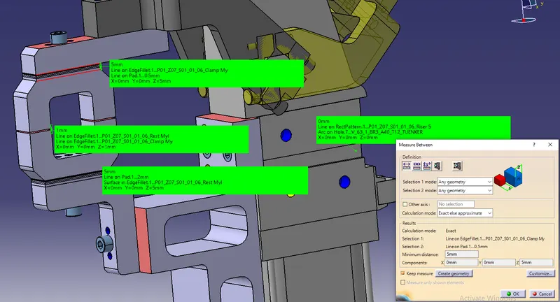
Checking the nominality of all the units:
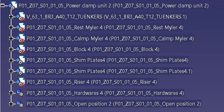
Renaming of all the Parts of POwer Clamp Unit:
Checking Parameters:
|
Checking Parameter |
Action |
|
Rename of the design tree |
Done |
|
Mark Machining Area |
Marked |
|
Mylars Splitting as per Panel profile |
Done |
|
Hole Concentricity |
Done |
|
Nominality |
Done |
|
Holes colouring standard |
Done |
|
Fasteners Implementation |
Done |
PIN UNIT:
A pin unit is a unit designed to locate the car panel using pins. There are two types of pin units. They are:
- Fixed pin unit
- Retractable pin unit
- Single Rod
- Dual rod
The below are the different parts of a fixed pin unit.
- Pin
- Pin retainer
- Shims/Spacers
- Blocks
- Blade/Adaptor plate
- Riser
- Cylinders
Fundamentals of Pin Unit Design:
It is necessary to have 2 pins to locate a car panel & here one pin must arrest 4 ways (4 translational) & other must arrest 2 ways i.e. 2 rotational) of a car panel.
The axis of the car panel hole & the axis of the pin should be same. The pin tolerance for a geo pin will be of closer tolerance i.e. 0.15mm & for re-spot pin is -0.28mm
- Pin should engage 3 to 5 mm from car panel entry surface.
- All pins should be accommodated with 2 way adjustable shims irrespective of direction of arresting.
- Round pins should be used in case of 4 way arresting of car part if the hole is round.
- Round pins can be used for 2 way arresting of car part only if the hole is slot.
- Diamond pins should be used in case of 2 way arresting of car part if hole is round
- Diamond pins should be used in case of 4 way arresting of car part if hole is slotted.
FIXED PIN UNIT:
The below are the different parts of a fixed pin unit.
- Pin
- Pin retainer
- Shims/Spacers
- Blocks
- Blade/Adaptor plate
- Riser
Indicating the Machined area:
Colouring Holes as per the standards:
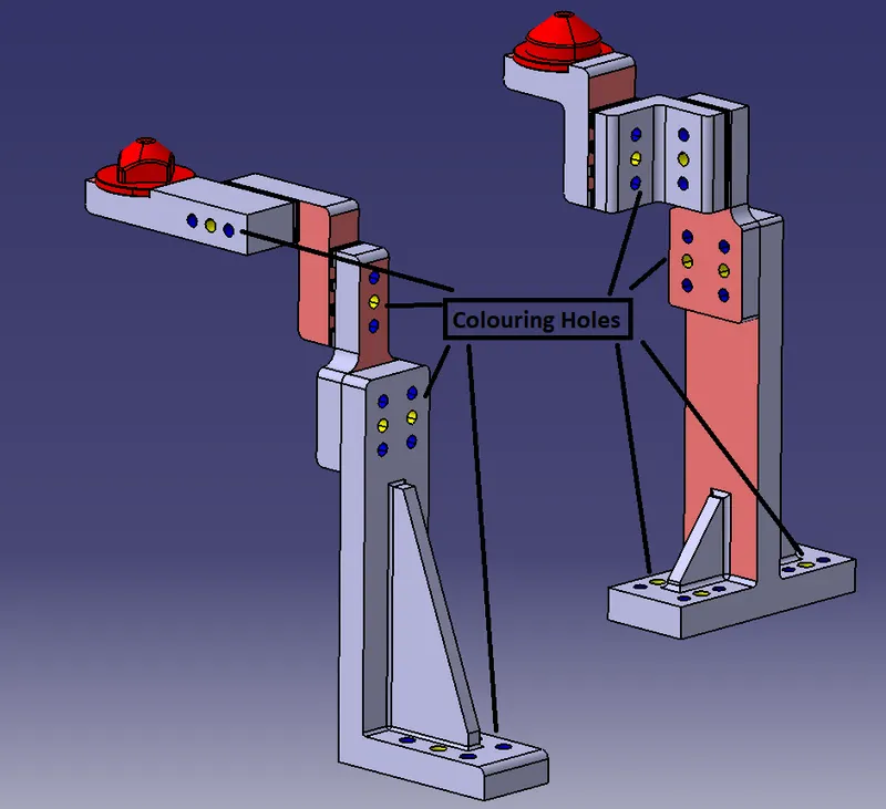
Fasteners Implementation:
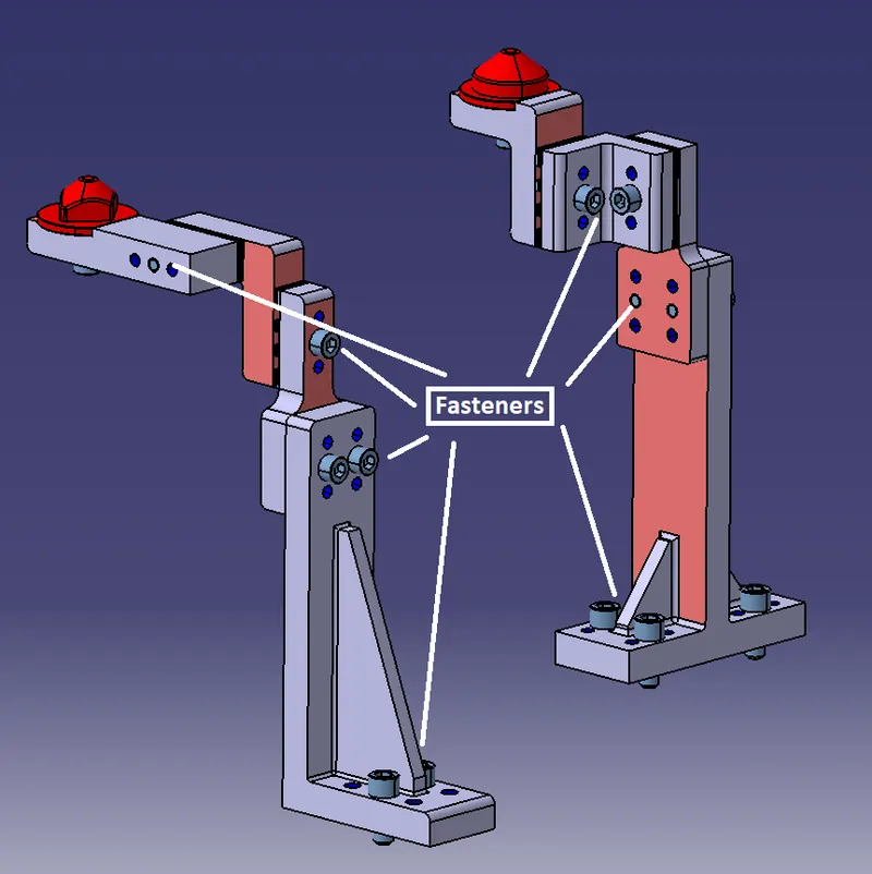
Checking the hole concentricity:
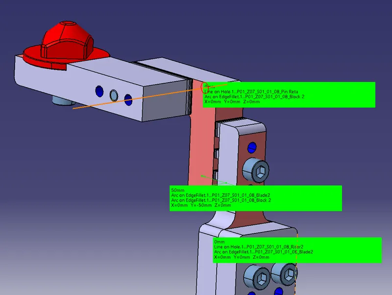
Checking the nominality of the Parts:
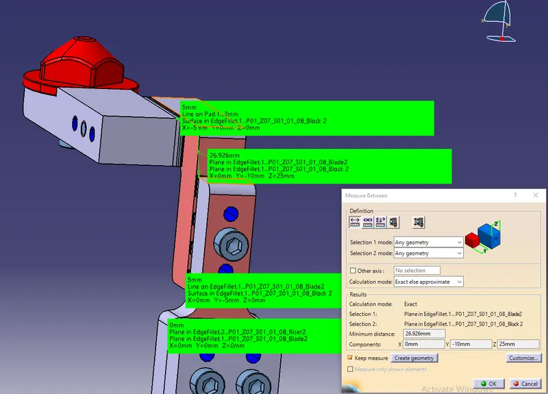
Renaming of all the parts of the pin unit:
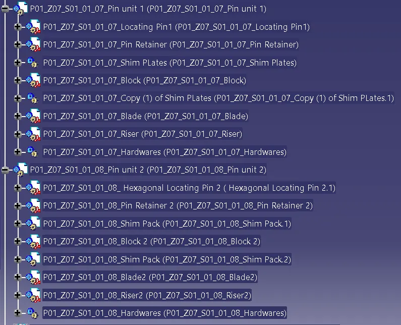
Checking Parameters:
|
Checking Parameter |
Action |
|
Rename of the design tree |
Done |
|
Mark Machining Area |
Marked |
|
Hole Concentricity |
Done |
|
Nominality |
Done |
|
Holes colouring standard |
Done |
|
Fasteners Implementation |
Done |
SWIVEL CLAMP UNIT:
Clamp Unit:
A clamp unit is a unit designed to clamp/hold the car panel with NC blocks/Mylars/rest by using a pneumatic cylinder. Clamp arm, finger, Rest/backup, L-block, shims, riser, pneumatic cylinders are the typical parts of clamp unit. Clamping force should be considered while designing clamp unit. Usually clamp open position is 90o.Fingers are attached to clamp Mylar. In Clamp unit shim to one side is more enough because it will restrict translation motion in upward direction and downward direction only. There is another type of clamp unit known as swivel type. There is pivot pin around which clamp arm rotate.
Parts of a Clamp Cylinder:
- Clamp cylinder:In clevis clamp unit, swivel type cylinder is used. Pneumatic Cylinder are mechanical devices which use the power of compressed gas to produce a force in a reciprocating linear motion. Like hydraulic cylinders, compressed gas or a fluid forces a piston to move in the desired direction. The piston is a disc or a cylinder, and the piston rod transfers the force it develops to the object to be moved. Engineers sometimes prefer to use pneumatic because they are quieter, cleaner and don't require large amounts of space for Fluid storage. Because operating fluid is a gas and its leakage from the pneumatic cylinder will not only drip out but, contaminate the entire surroundings. Making pneumatic more desirable where cleanliness is a requirement.Once actuated, Compressed air enters into the tube at one end of the piston and imparts force on the piston in other direction. Consequently, the piston gets displaced.
- Rest Myler:A Mylar is an NC block which is mounted on the clamp arm of the cylinder and it presses the car panel to the Rest Mylar, so therefore holding the car panel.
- Clamp Myler:A Clamp arm is a make part, it is made as per the positioning of the clamping cylinder, Stopper and shims. Clamp arm is made from Hard material.
- Clamp Arm:The distance between the pivot point and the cylinder mount should be 50mm. This is necessary because cylinder stroke is 100 mm and it must be achieved when it is at 900 position and clamp arm mounting hole must be in line with the cylinder.
- Stoppers:The function of the stopper is to restrict the movement of the clamp from going beyond the limit. Stopper is mounted between Clamp arm and Blade. Stopper has two parts, Male stopper and a Female stopper. The Male stopper is attached to the clamp arm and the Female Stopper is attached to the Blade. When these two Parts meet, they restrict the motion.
- Blade:A blade is a make part designed according to the position of the riser, clamp cylinder, Clamp arm, Rest Mylar and stopper.
- Riser:A Riser is a standard part or a make part which provides height to the pin unit, Clamp unit as per the requirements. Riser should have adequate strength so it can sustain the load of the car panel, Clamping cylinder, Blades.
- Bushes:Bush is friction type bearing. It is lubricated with grease, oil. It permits relative motion between mating parts. It is made of hard material also ID and OD are precisely machined or grinded. It is Press fitted and after worn out it is replaced with new one instead of replacing other part which save cost. Mostly Phosphor bronze or gun metal is used for manufacturing of bushes.
- Shim Plates:In Fixture, we are providing tolerance to each part mostly manufactured. Those tolerances tend to stack up and Reflect together. In order to avoid that we use shims so we can easily adjust after assembly so whatever stack up there we will rectify it through shims. Shims come in thickness of 0.1,0.2,0.5, etc.We provide shim to accommodate clamp as well as rest mylar in two directions. Clamp & rest mylar can be adjusted in one direction only i.e., up or down. Also, two-way shim provided for locating pin to accommodate adjustment.
Design of Swivel Clamp unit:
- Study the PLP (Principal location Points) data along with the nearby spot data.
- Depending on the angle of cross section. Mylars will be having shimming either in one direction or in 2 directions. General thumb rule if the section is inclined more than 150 or clamping surface is 3D profile then 2 direction shimming are provided
- Take an overview of the working height if you're having manual welding. For robotic welding also it's important to see the working height in consideration of the robotic gun, turntable height if manual loading is done.
- Put the proper gun at the spot location. If process engineer has gun shape stick to X, C or Y type of gun. Do the proper gun study and place the gun as per the Geo or re-spot decision and operator approach. Once basic gun is placed considering the throat depth and throat gap start building the clamp and rest block at the PLP.
- Panel section creation: Take a section at PLP either in clamp opening direction or normal direction Sections should be normal to base. Panel section through X, Y or Z direction passing through PLR Section will help it finalizing the shape of clamp and rest block. Most importantly used for finalization of gun shape.
- Finalization of a base plate plane: Consider following things before deciding the base plate Height of maximum and minimum weld spot from the floor. No gun arm should touch the base plate. Operator ergonomic while accessing all the spots.
- Construction of Rest and Clamp block: If standard Mylar has to be used (Few companies make standard height and length of steel blank with few holes and dowels for clamping) they select the proper blank size as per the requirement consider 0.5 mm above the panel.
- Select the clamping cylinder as per the pivot point distance from the PLP Once clamp and rest block are built, start construction of mounting plate or lubrication structure as per the company standard to make the connection with the base plate, shimming is 2mm solid+3mm shim pack. In few companies 3mm shims are used. Make connection plate between rise and Mylar Material can be C45, Teflon, Aluminium or S-Gurn as per the customer requirement Generally S Gurn Mylars are made of more thickness.
Factors to be considered while designing a clamp unit:
- There should be adequate space between the cylinder and another part like riser, car panel because cylinder moves or swing while opening and closing.
- Pin clam unit is used where two panels or components are located and clamp for welding.
- Clamp make is in such a way that it clamps two car panel at once.
- Every clamp Mylar should have rest Mylar.
- Clamp unit has shims in only in one direction.
- All parts should snap and butt properly to each other.
- Make sure that parts of the clamping unit are min 10 to 12 mm away from the car panel, so they don't damage the car panel.
- Design tree should be structured in a way that makes a part on the top and followed the standard part.
- Avoid any clash, it will not rise issue at assembly.
- The product design should be in such a way that it will be easy to make, assemble and quality check.
- We should preferably use quick acting clamps, the clamping method will not damage the work piece. The clamp should be open in such a way that clamp arm moves away from the operator.
- There must be adequate clearance for loading and unloading. So, the process becomes fast and easy. The Size variation must be accepted.
- Avoid sharp edges and corners, they can harm the operators and cause a serious injury. Provide chamfer or fillet to the corner.
- The fixture must possess sufficient rigidity and robustness. It should not vibrate as it can lead to unwanted movement of the work piece and tools.
- Must ensure security in the operation.
Implementation of fasteners:
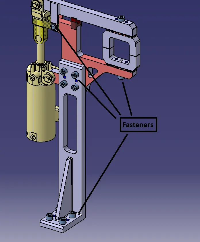
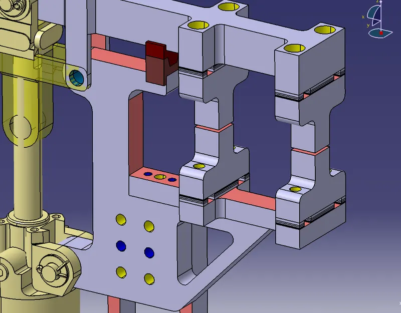
Holes Colouring as per the Standards:
Yellow - Threaded hole
Blue - Dowel hole
Indicating the Machined area:
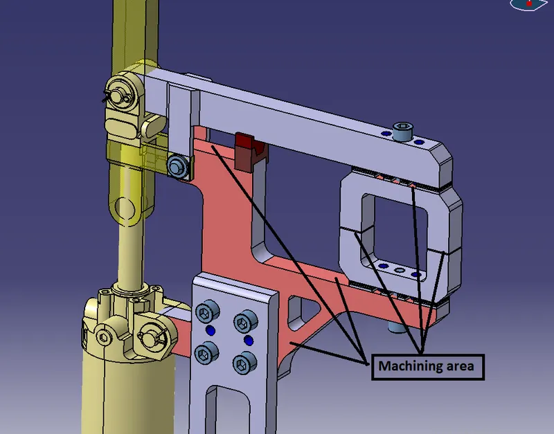
Checking the nominality of all the parts:
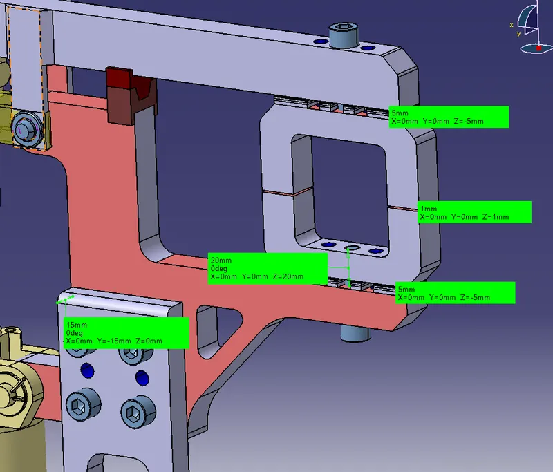
Renaming of all the Parts:
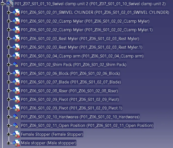
|
Checking Parameter |
Action |
|
Rename of the design tree |
Done |
|
Mark Machining Area |
Marked |
|
Hole Concentricity |
Done |
|
Nominality |
Done |
|
Holes colouring standard |
Done |
|
Mylar Splitting as per panel profile |
Done |
|
Fasteners Implementation |
Done |
PIN CLAMP UNIT:
Fasteners implementation:
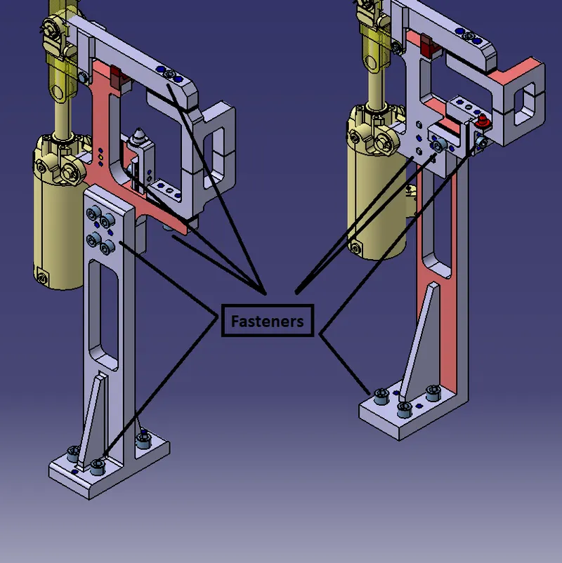
Indicating the Machining area:
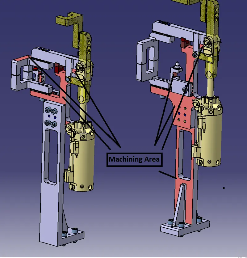
Mylars Splitting as per the Panel profile:
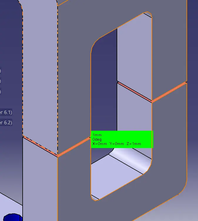
Checking the Nominality of all the Parts:
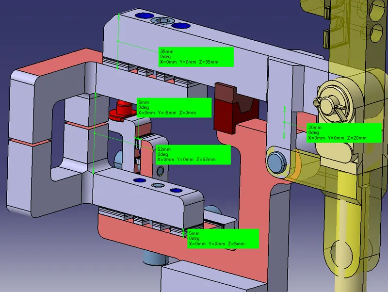
Renaming of all the Parts:
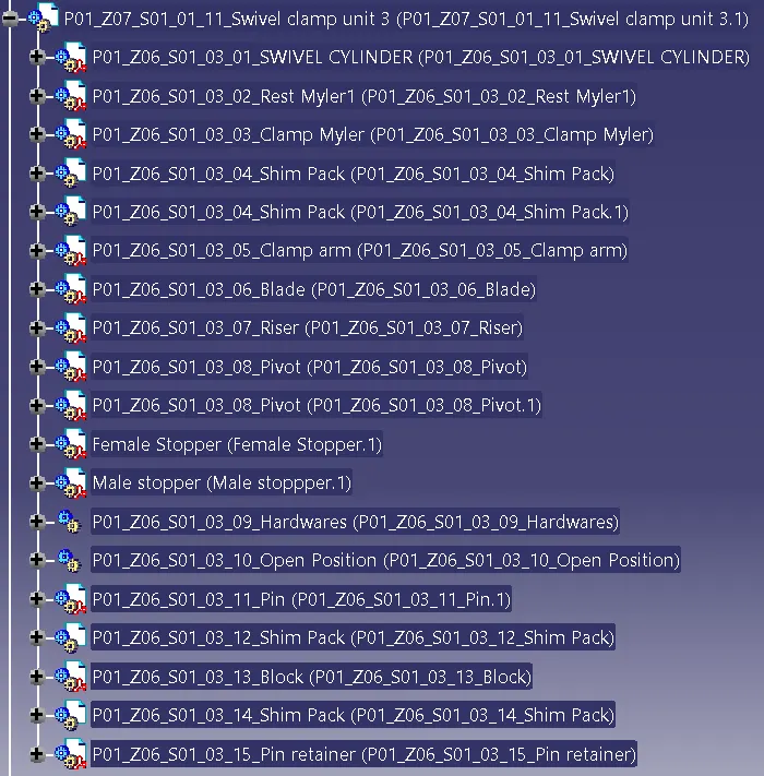
|
Checking Parameter |
Action |
|
Rename of the design tree |
Done |
|
Mark Machining Area |
Marked |
|
Hole Concentricity |
Done |
|
Nominality |
Done |
|
Holes colouring standard |
Done |
|
Mylar Splitting as per panel profile |
Done |
|
Fasteners Implementation |
Done |
RETRACTABLE PIN UNIT:
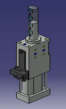
A retractable pin unit is a unit designed to locate the car panel using pins, but the entire pin package parts will be mounted on the retractable pneumatic cylinder.
Cylinders:
SZK_40_1_BR3_A14_T12_TUENKERS:
Pneumatic cylinder in aluminium block design with precision guide of the piston rod, secured against rotating. Compact Housing Made from High Strength aluminium with mounting options on several sides. Drive mechanism with circular section cylinder for the thrust forces and extraction forces of approx.350/250N.Total strokes 40mm integrated inductive sensitive sensing system.
Colouring holes as per the standards:
Yellow - Threaded Hole
Blue - Dowel Hole
Cyan Blue - Blind hole
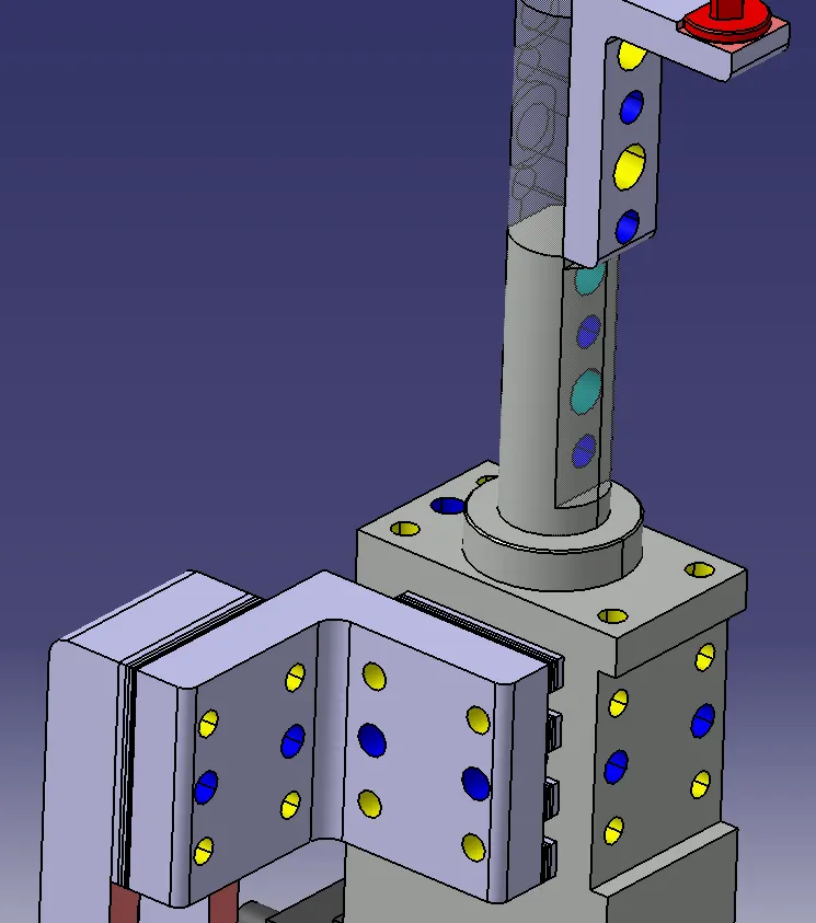
Fasteners Implementation:
Indicating the Machining area:
Checking the nominality of parts and holes:
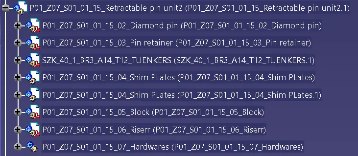
Renaming of all the Parts:
|
Checking Parameter |
Action |
|
Rename of the design tree |
Done |
|
Mark Machining Area |
Marked |
|
Hole Concentricity |
Done |
|
Nominality |
Done |
|
Holes colouring standard |
Done |
|
Fasteners Implementation |
Done |
IMAGES OF ALL THE UNITS USED IN THE ASSEMBLY AFTER 3D FINISHING:
Panel:
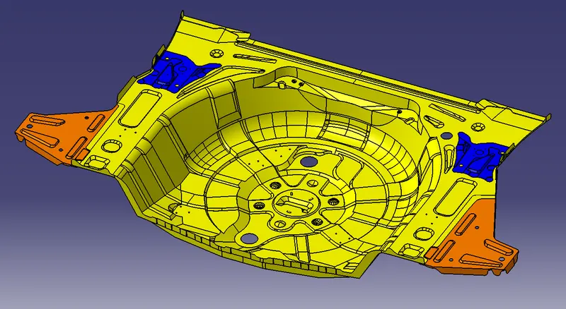
Base Unit after 3D Fininshing:
Rest Units:
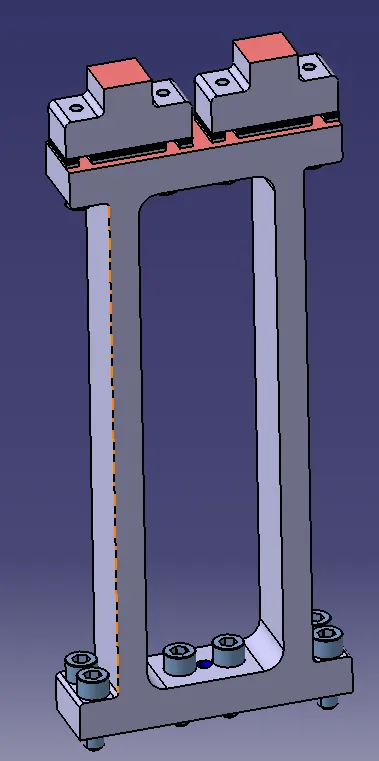
Power Clamp Units:
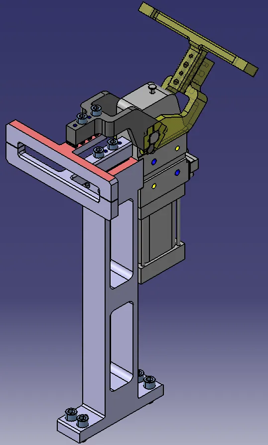
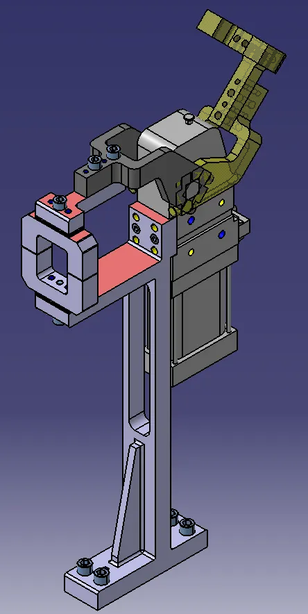
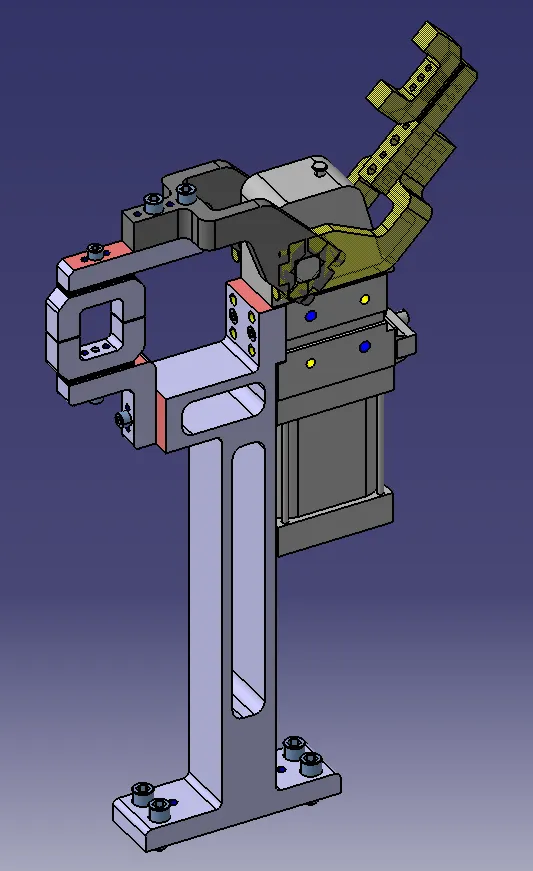
Pin Units:
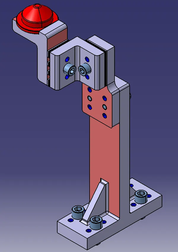
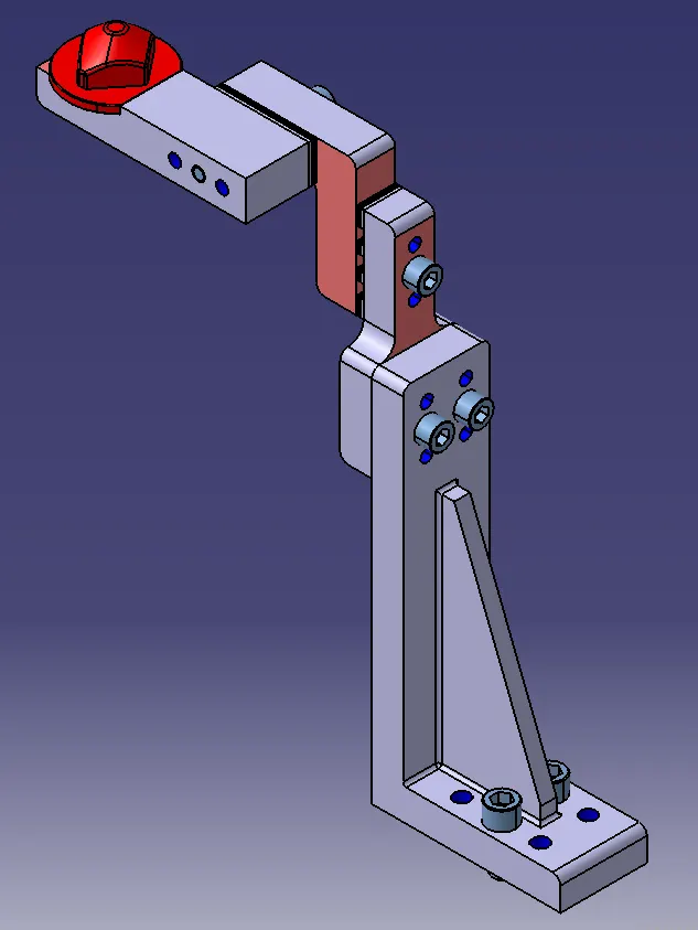
Swivel Clamp Units:
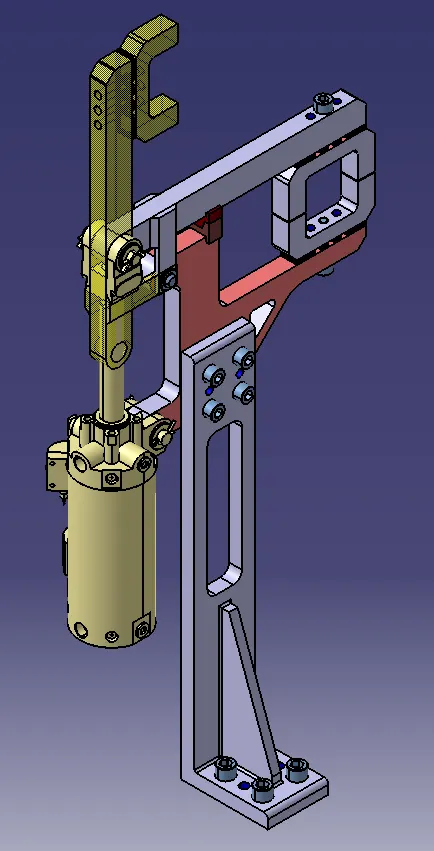
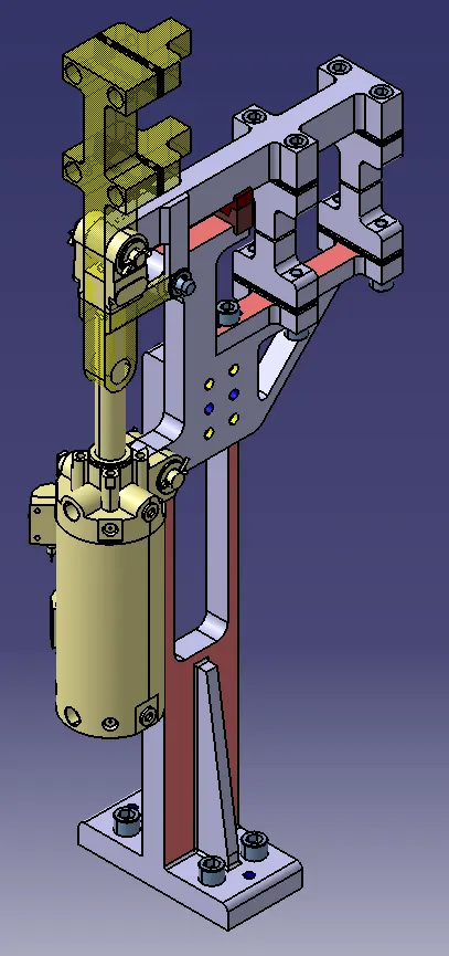
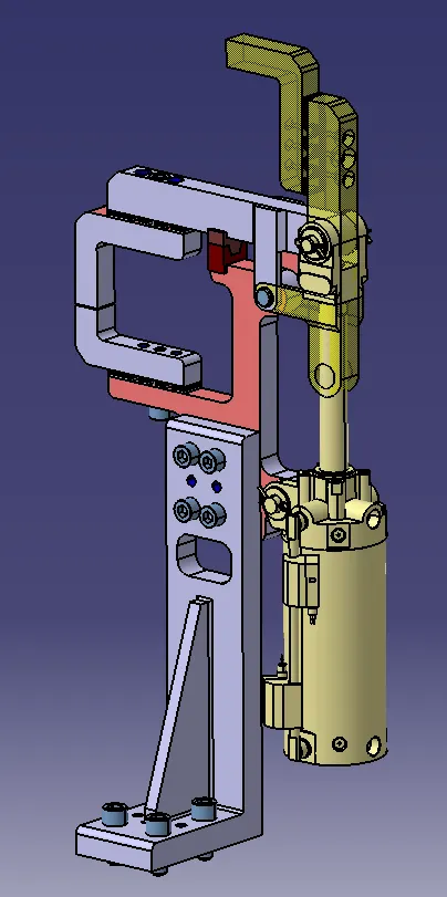
Pin Clamp Units:
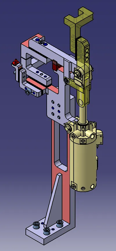
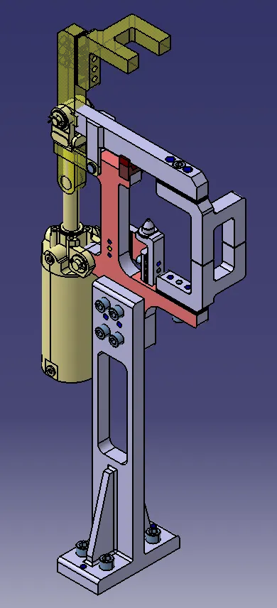
Retractable Pin Units:
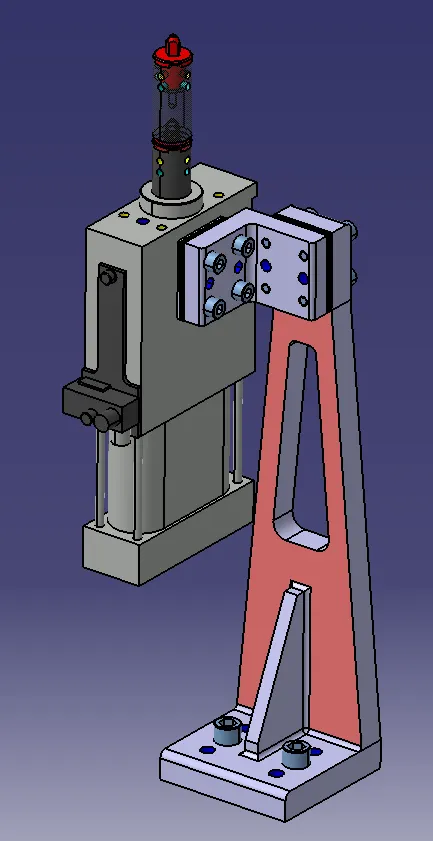
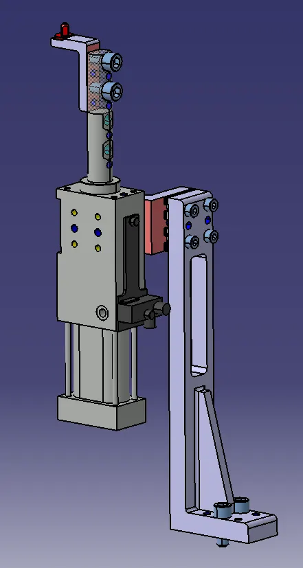
Positioning of the units on the Base Plate:
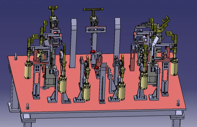
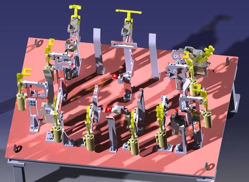
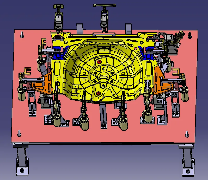
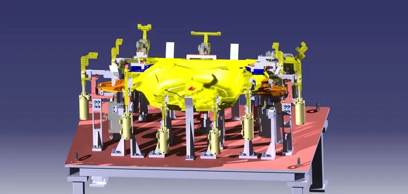
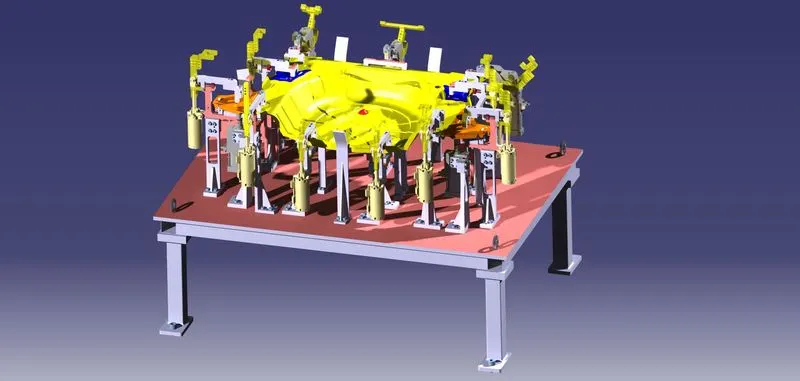
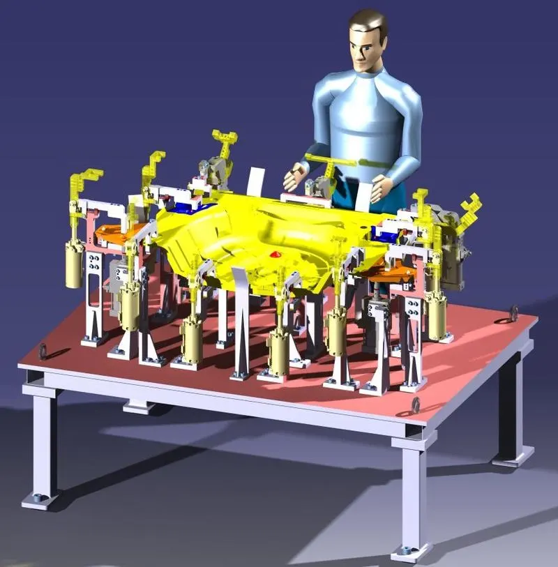
FINAL IMAGE OF THE FIXTURE:
CONCLUSION:
Hence, 3D finishing is performed on the designed Assembly of Fixtures and Rough Locators were designed for the given panel.