Week 8:- 3D Finishing Challenge 2
3D FINISHING & DESIGNING OF ROUGH LOCATORS
AIM:
To perform 3D finish and create rough locators for the assembly design created forthe given car panel.
SOFTWARE USED:
CATIA V5
CAR PANEL:
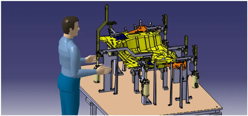
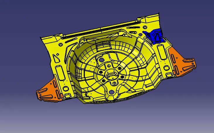
3D FINISHING:
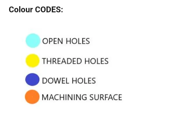
It is the process which is carried out before final simulation.Each and every units and every parts of the units are checked for nominal positons , proper budding,inline,clearences, and anyother clashes with other units are checked and verified.The part should be checked for proper clearences and reperenting the machining sides of a part by applying color codes.In this process the part is checked with hole concentricity,designing of rough locators for guiding the panel.Fasterners are implemented as per the hole size & the standard color codes as per the customer requirement are applied to differentiate the type of hole,threaded hole,or clearence hole.Remaining of the assembly & the part is done to give every part of different identity so everyone can identify in which assembly this part is going to be fit.After doing all this things the model is sent for simulation and 2D detailing.
ROUGH LOCATORS:
- Rough locators are basically used where manual loading of panel is implemented on the fixture.
- These are used to guide the panels to correct positions and oreintation.
- These also helps for proper POKA-YOKE([poka-yoke] is a japenese term that means 'mistake-proofing'or 'inadverdent error proofing'.).Poka-Yoke ia any mechanism in any process that helps an eqipment operator avoid(yoke) mistakes(poka).
- Materials used for rough locaors are mild steel (MS) or other similar metals.
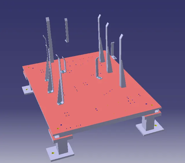
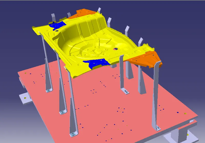
Following points needs to be considered while designing rough loactors:
- Height of the rough locators should not be the ergo data of the fixture.
- The entry point or top point of the rough locator must be 10 -15 mm above the panel surface.
- Rough locators should have the adjustment in the direction of guiding plane.
- 2mm gap to be maintained between rough locator and the panel at the time of design and we can provide 5 - 10mm in the positive or negative direction of guiding plane.
- Rough locators can be rod type or flat type depending upon the standards and other condiions.
GUN STUDY:
Welding is predominantly used in manufacturing industries and requirements for fixtures that ease the welding process is a continous developement task in any industry.Car body-in-white (BIW) is a complicated steel structure including 300-500 sheets with complex shape and assembled by means of welding in a high rhythm through 55-75 robotic work stations.The foremost step taken before starting the design of welding fixture is to arrive at the spot welding locations.The locations and orientations of other critical units of the fixture including clamps,locators,etc.,are decided based on weld spot distribution.The weld spot for front door inner panel side bracket assembly are located .
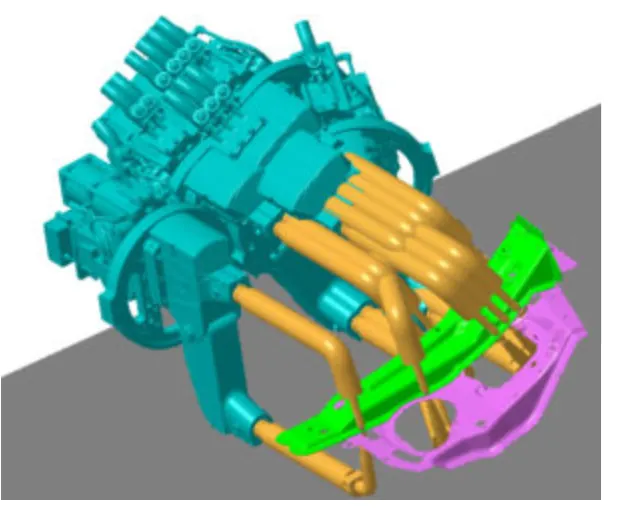
There are two types of weld points one is geo weld points which ensures the geometry of the assembly and the 2nd one is the respot weld points which adds strength to the already welded part.
The device used to make spot welding on the panel is called gun.The gun may differ deoending upon the appliccation.Fixtures will be designed by considering the weld spots on the panel.After designing the fixture the cad file of the gun be placed on the weld spot to check weather the gun is clearence with the fixture.After adjusting the fixtures the coordinates of the welds be taken for further operations of gun.
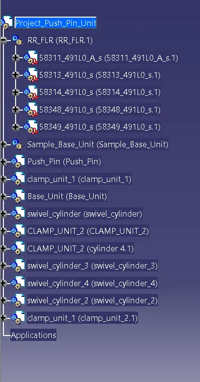
DESIGN TREE:
3D FINISH:
In 3D finish we perform and ensure following points:
- Naming of parts.
- Structuring of design tree.
- Holes concentricity.
- Nominality.
- Machining surfaces.
- Mylar spliting.
- Gaps checking.
- Budding of parts.
- Make changes if any clash.
- Tooling hole.
- Fastners(Washers,bolts,dowel pins,etc.)
Pin units and pin-clamp units cannot be maintained to nominal positions because the holes in the panel itself not nominal.
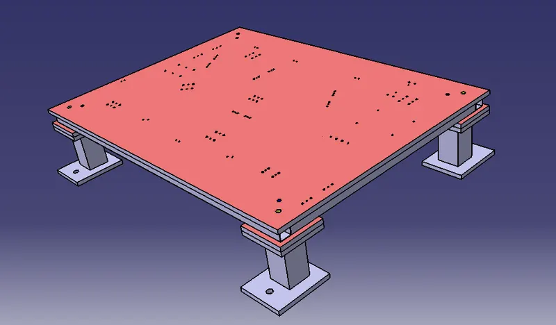
1.BASE UNIT:
- BASE UNIT is the unit in which all other units are mounted on it.
- Threaded holes and dowel holes should be done at nominal positions and color coding must be done to distinguish the holes easily.
- Threaded hole-YELLOW
- Clearence hole-SKY BLUE
- Dowel hole-BLUE
- Machining surface-ORANGE
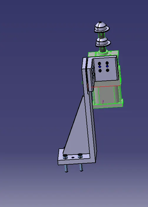
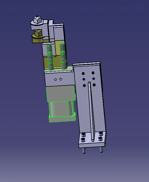
2.FIXED PIN UNITS:
Holes are make to the nominal and concentric to each other.
Proper budding of two parts is done.Rough locators and fastners are implemented .
Color codes done as per the standards.
Structuring design tree and renaming of parts is done.
Below are some of images after 3D finishing done of fixed pin unit.
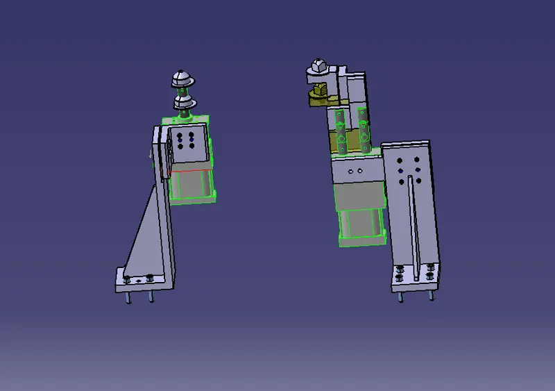
3.RETRACTABLE PIN UNIT:
- Holes are make to the nominal and concentric to eachother.
- Open position of retactable pin unit shown in light color of optimacity 25%.
- Proper budding of two parts is done.
- Color coding is done as per the standards.
- Structuring design tree and renaming of parts is done.
- Below are the some images after 3D finishing done on fixed pin unit.
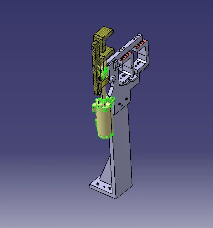
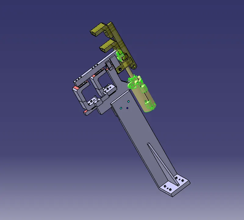
4.SWIVEL CLAMP UNIT:
- Holes are make to the nominal and concentric to each other.
- Proper budding of two parts is done.
- Rough locators and fastners are implemented.
- Color coding is done as per the standards.
- Structuring design tree and renaming of parts is done.
- Mylar spliting is done.
- Consider the thickness of the panel is 1 mm .,
- Open position is shown in yellow color.
- Move the entire unit to nominal position with respect to base unit and put holes to the base unit.
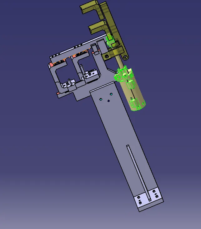
- Below are the some images after 3D finishing done on swivel clamp unit.
5.POWER CLAMP UNIT:
- Holes are make to the nominal and concentric to each other.
- Proper budding of two parts is done.
- Rough locators and fastners are are implemented.
- Color coding is done as per the standards.
- Structuring design tree renaming of parts is done.
- Mylar spliting is done.
Consider the thickness of panel is 1 mm.
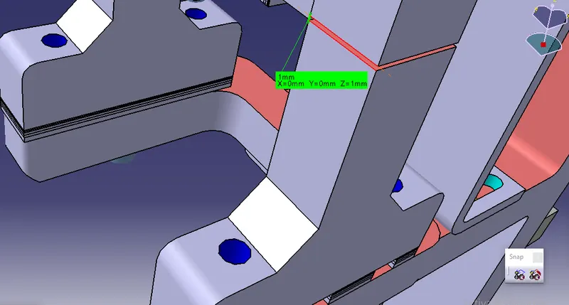
- Open position is shown in yellow color.
- Move the entire unit to nominal position with respect to base unit and put holes to the base unit.
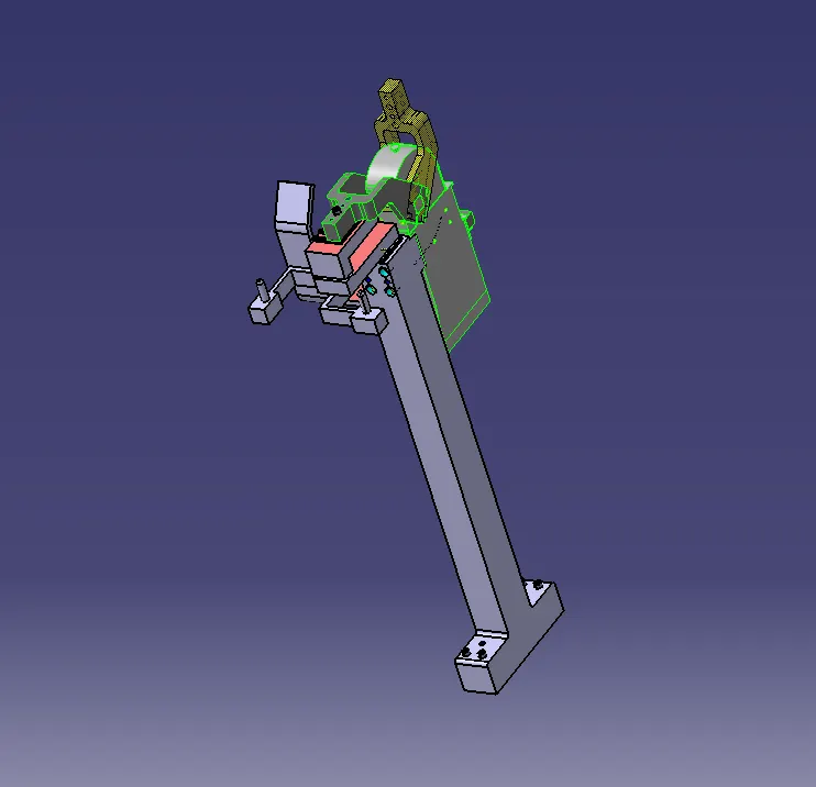
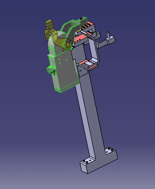
- Below are the some images after 3D finishing done on power clamp unit.
6.REST UNIT:
- Holes are make to the nominal and concentric to each other.
- Proper budding of two parts is done.
- Color coding is done as per the standards.
- Structuring design tree renaming of parts is done.
- Move the entire unit to nominal position with respect to base unit and put holes to the base unit.
- Below are the some images after 3D finishing done on Rest unit.
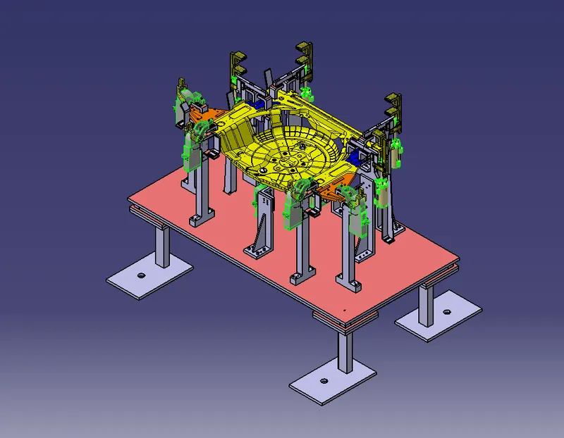
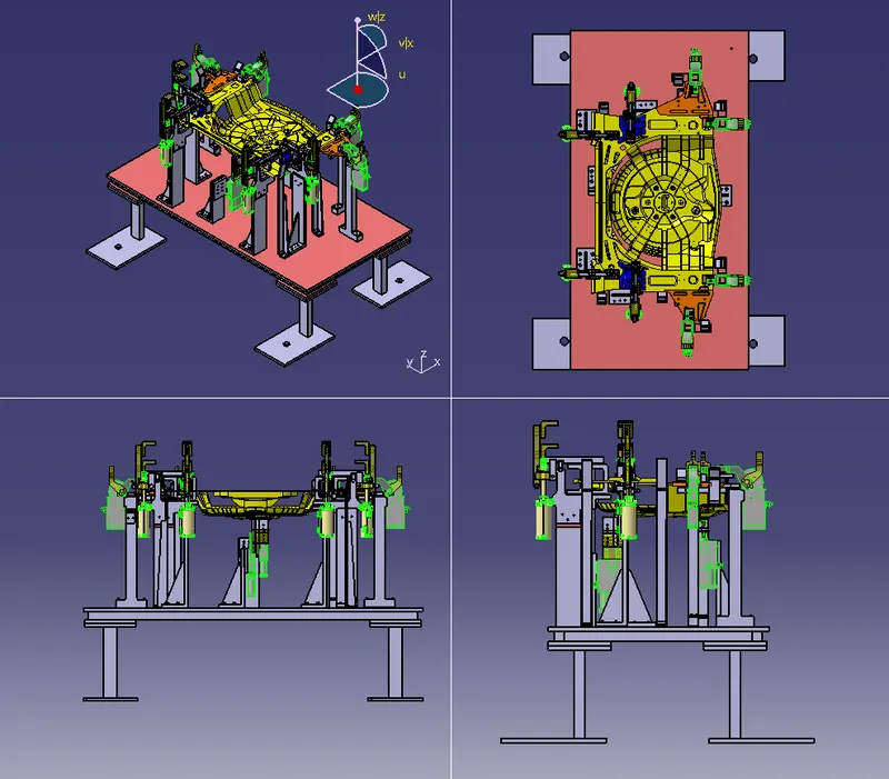
FINAL RENDER IMAGE OF FIXTURE:
ISOMETRIC VIEW:
CONCLUSION:
This way i designed all units required to fix the car panel and also it is achived 3-2-1 principle and perform 3D finish and Rough locators for the assembly design.