Week 8 - Challenge 3 - Switch Bezel Design
AIM:
To create the Switch Bezel plastic component through the given Class-A surface and at the end performing the draft analysis on the model.
OBJECTIVES:
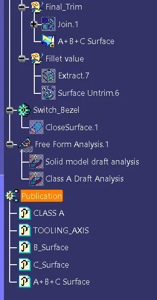
- To ensure proper tree structure is followed.
- Geometrical sets should have a proper name based on the sketches present inside of it.
- All the sketches should be created under the geometrical set.
- Use of the Close Surface feature to make a solid body from the surface.
- To publish the tooling axis, class A, B and C surface.
PROCEDURE:
First import the Class A Surface of Switch Bezel model in CATIA V5.
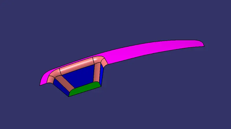
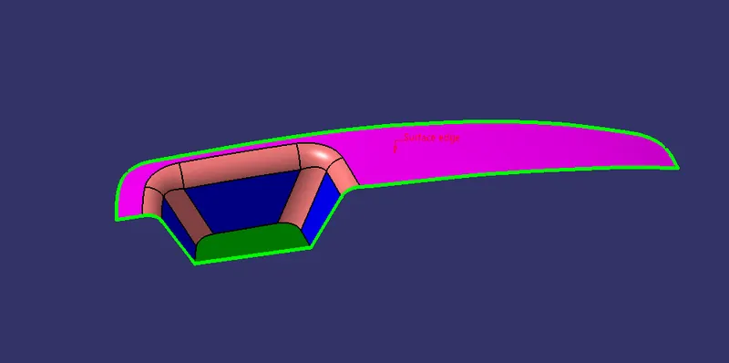
Check the connectivity of Class A Surface using boundary option. Ensure that there is no gap between the two surfaces.
TOOLING AXIS:
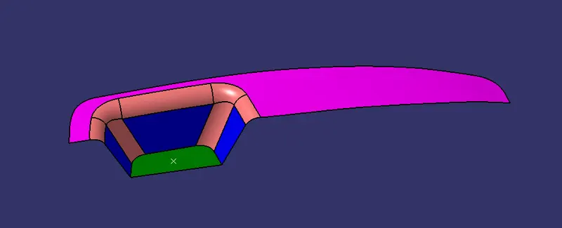
Now we need to create the tooling axis the base bracket model. Visually check which direction is better for creating tooling axis. Now in order to create the tooling axis in Z-direction, first create a reference point on any surface as shown in below figure.
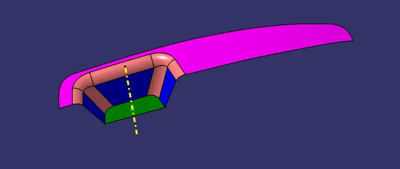
Now using the reference point, create a line in Z-direction. This line will give us the tooling axis.
CLASS B SURFACE:
- Consider the thickness of the component as 2.5 mm. Now we need to create a B surface which w of 2.5 mm be similar to the A surface at an offset value
- In this operation we creating a Class B surface in 3 different geometrical sets
- First we are creating a Top Rest. To create this surface we need to extract the Class A surface as shown in below figure.
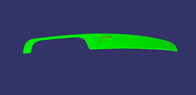
Once the surface is extracted untrim it and then extrapolate it by a required value on each side using point continuity. Now offset it by2.5 mm.
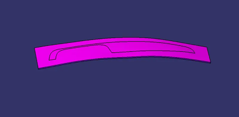
Similarly, we need to extract the Walls and Base surface of the Switch Bezel in different geometrical sets and perform similar operations on it as mentioned above.
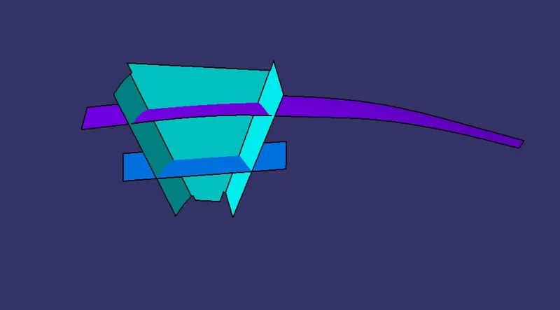
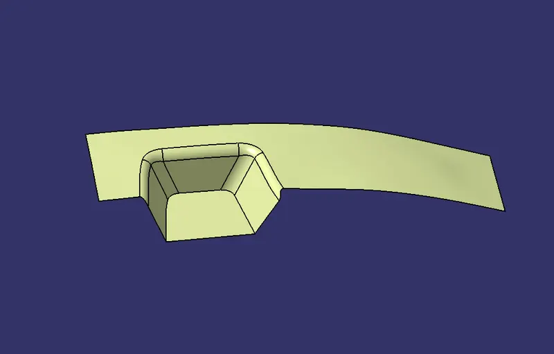
Once all the surfaces are created trim these surfaces to form a Class B surface. Give the appropriate fillets to form Class B surface.
CLASS C SURFACE:
To create a Class C surface, first extract the boundaries of the Class A surface and give them smooth curve as shown in figure below.
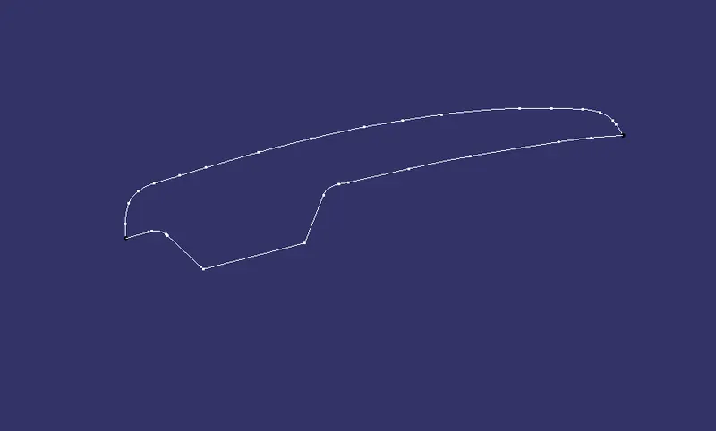
Now using the sweep option create the surface. To perform this operation, Go to the Toolbar> Sweep > Profile type > Line> Subtype> With draft direction > Guide curve 1- (select the extracted boundaries) > Draft direction - (select the tooling axis) > angle and length as 3 deg and 4mm respectively and click ok.
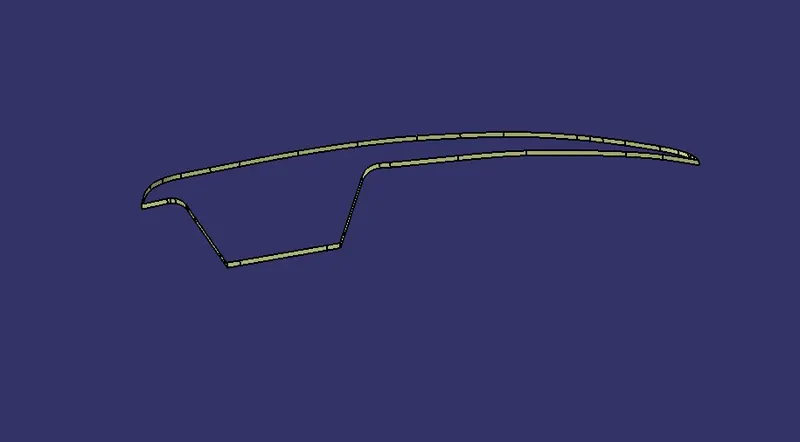
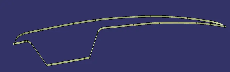
As there is some gap between these two surfaces, extrapolate these surfaces with appropriate value and trim them to form Class C surface.
TRIM SURFACES:
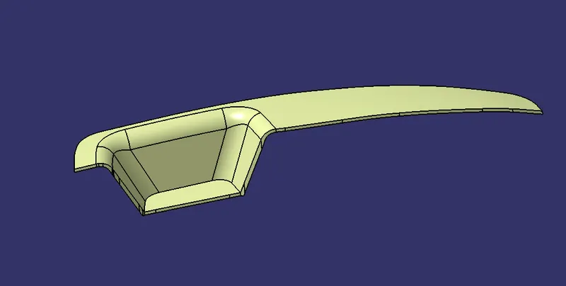
After creation of Class A, Class B and Class C surfaces, we need to join Class A and Class C surface to form a new surface. Then trim the joined surface with Class B surface to form the final required surface.
Solid Body:
Now using the close surface option from part workbench to a solid body from surface body.
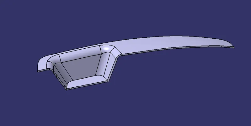
Different Views:
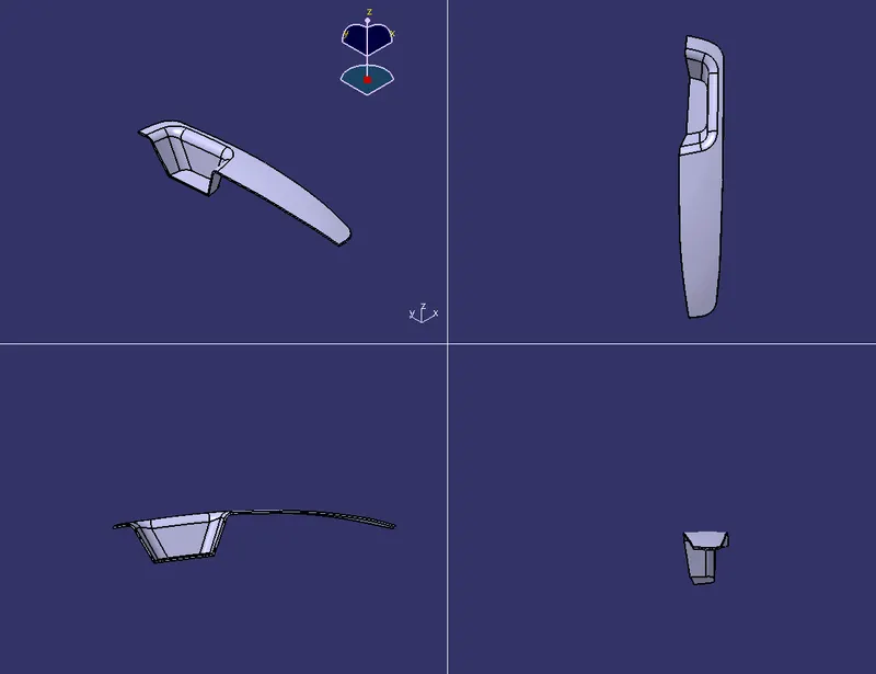
DRAFT ANALYSIS:
To perform Draft Analysis on the switch bezel model, first set the view parameters to Material Mode.
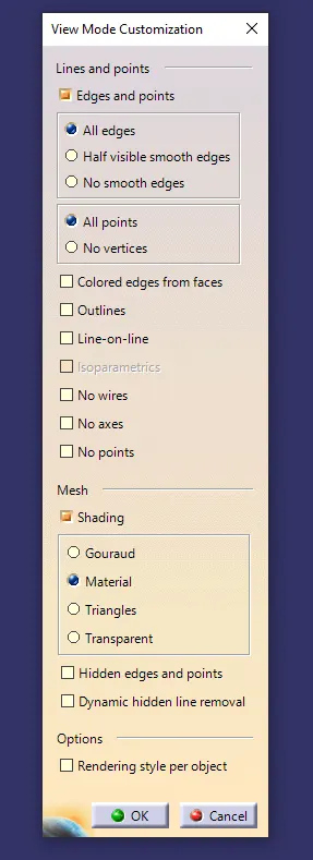
Then Go to menu bar> select insert> Analysis > Feature Draft Analysis.
To give the draft direction, use the compass and align Z-axis of it with the final tooling axis for the switch bezel model. Once it is properly aligned, lock the draft direction. Select the switch bezel and it will show us the current draft angle of the model. Set the draft value to 3 deg under the colour scale variant and press ok.
CLASS A SURFACE DRAFT ANALYSIS:
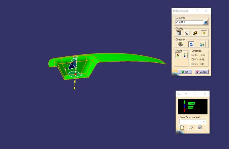
SOLID BODY DRAFT ANALYSIS:
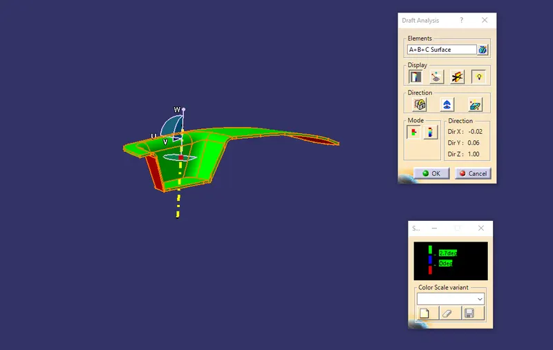
Using the Analysis option, we can perform the draft analysis on Class A surface and final part body of switch bezel.
To publish the Tooling Axis and Class A, Class B and Class C surfaces first select them and then Go to menu bar> Tools > Publication. This will publish the Tooling Axis and Class A, Class B and Class C surfaces which will be available in the Tree structure.
Tree Structure:
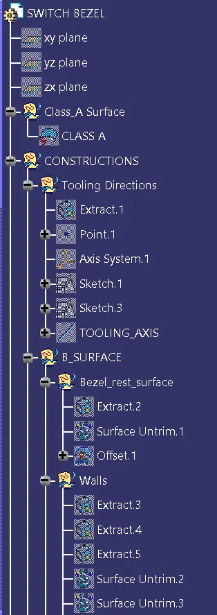
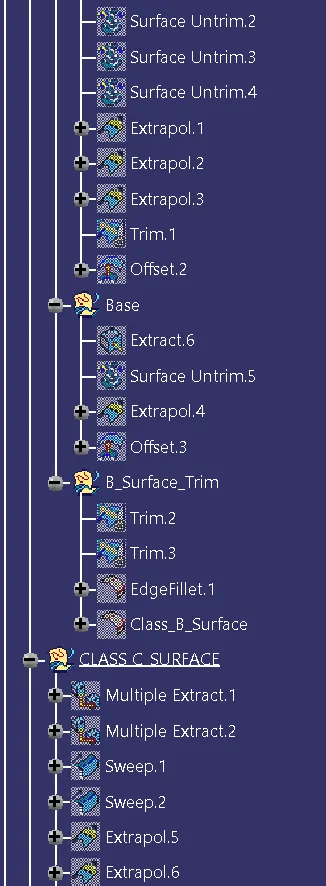
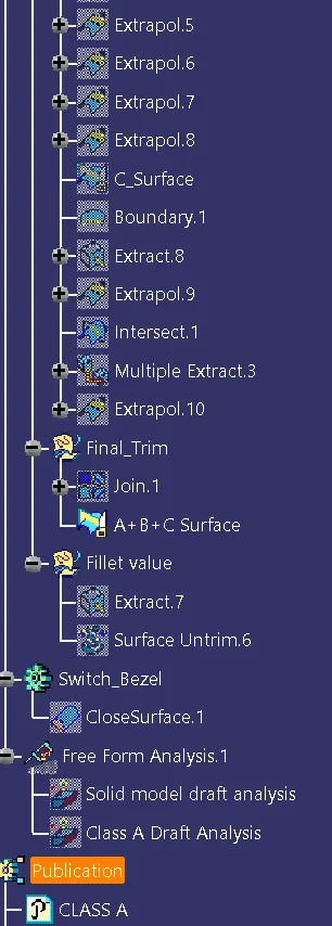
CONCLUSION:
Switch Bezel plastic component using Class A surface have been successfully created and draft analysis have also been performed for the same.