Door Arm Rest Week 8 Challenge
AIM:
- To create a door arm rest from the given class A surface by adding a thicknes of 2.5mm to it and also carry out the draft analysis of the component.
Tooling Axis:
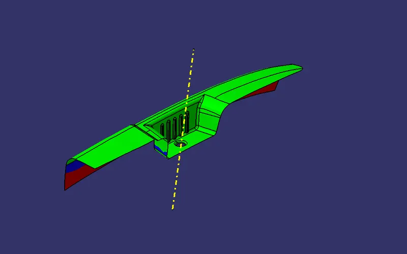
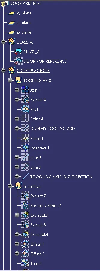
- Tooling axis is nothing but the direction in which the core and cavity opens and closes. Design engineer works is to analyse the Class A surface and find out the best possible tooling direction keeping in mind all the draft angle is with respect to the tooling axis so that the component can be easily ejected from the moulds.
Class B Surface:
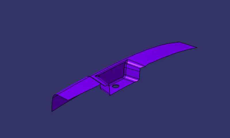
- To create a B surface, we need to offset the Class A Surface but the Surface cannot be the same as the Class A as it would create errors while the model is sent for prototyping.
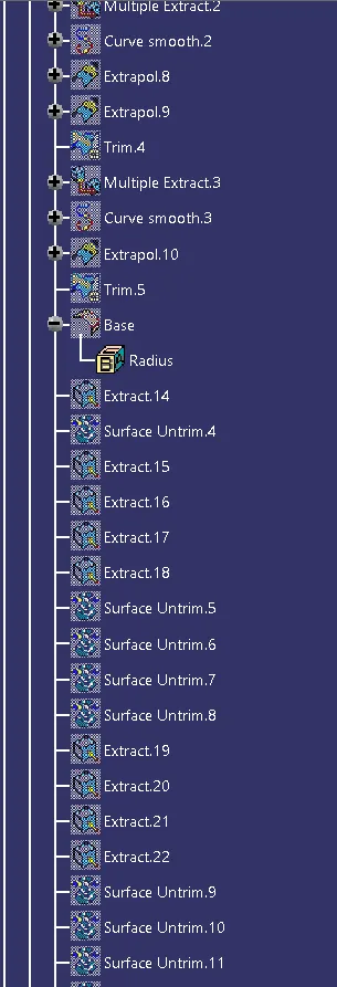
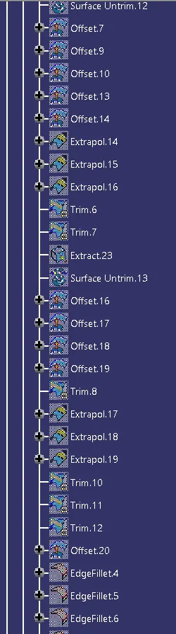
- We start with extracting the Top surface and Offset it to the thickness of the model (that is 2.5mm). Now, extract the groove parts and the base part and offset it to the same thickness.
- Now un-trim the extracted surfaces and extrapolate the surfaces such that every surface intersects with the neighboring surfaces. After completing the extrapolating, trim the surface such that the extracted surface is similar to that of the class A-surface (without fillets).
- The surface then needs to be filleted as the Class A surface with the 2.5mm added or removed by fillet radius.
Class C Surface:
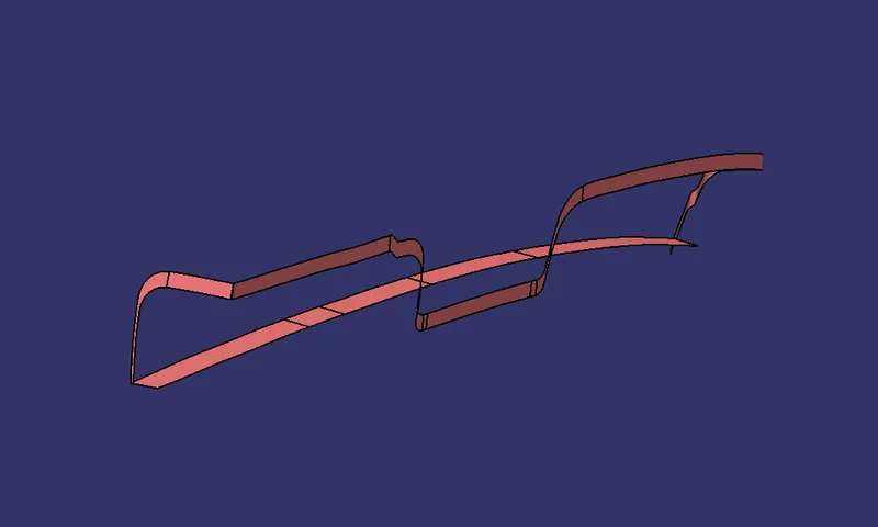
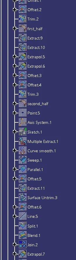
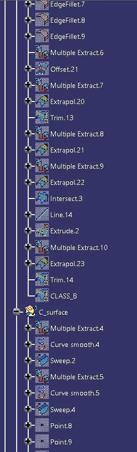
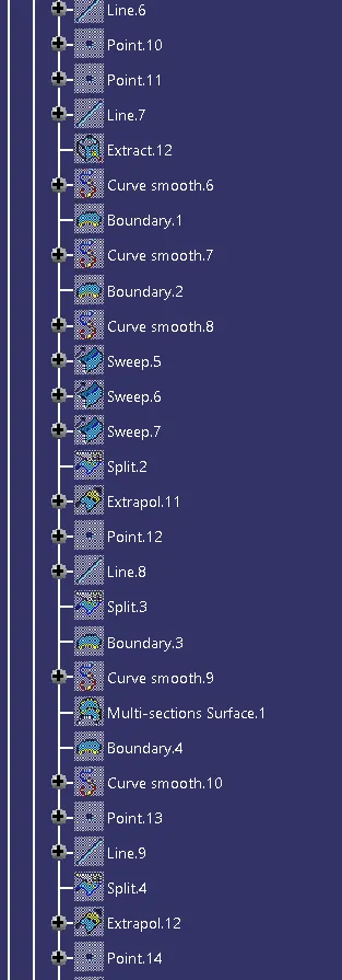
- Create a boundaries on class A surface on step by step based on staright plane and curved planes.
- Creates boundaries differently divided by the angle of boudary.
- Crerate sweeps on boundaries.
- We will get small gap between the surfaces its cleared using with joinig otption.
- Trim the sirfaces and join the classA And class b surfaces than will get c surface.
Joining Class A+B+C:
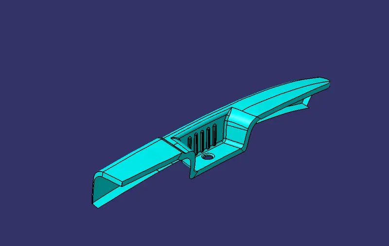
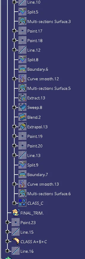
- Start with the joining the class A and class C surface together.
- Next trim the combined surface with the class B surface to create the final surface.
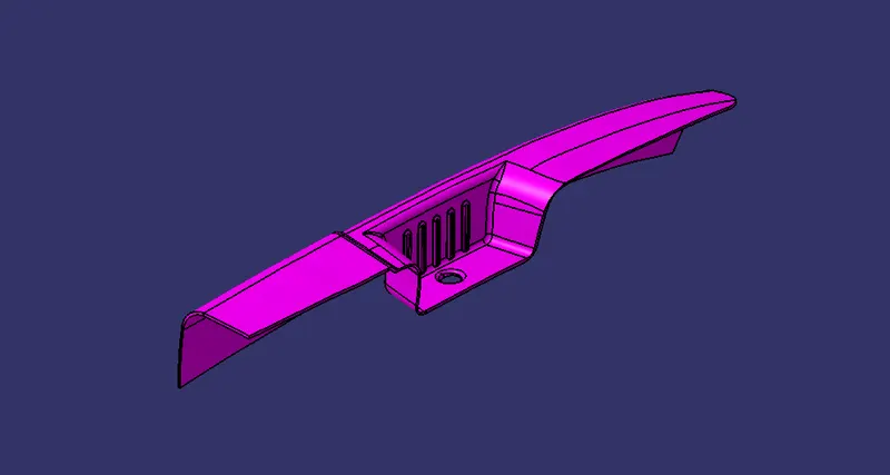
Solid body:
- Go to part design and insert a solid body.
- Create a closed surface.
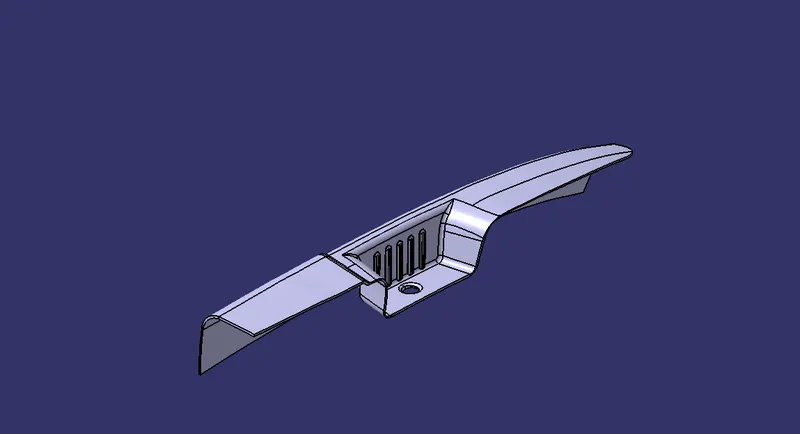
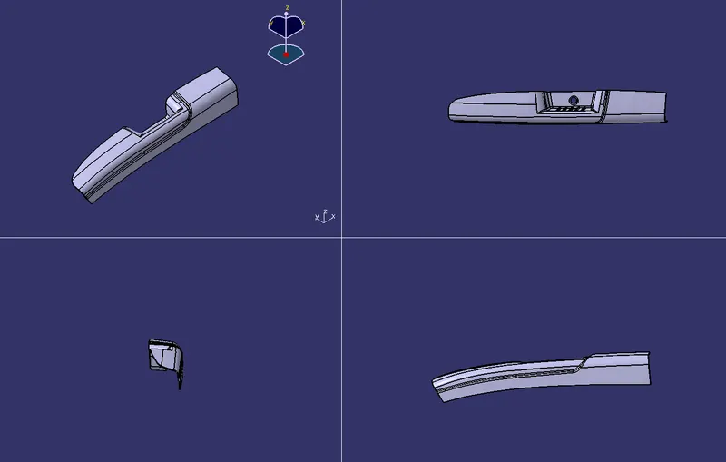
Different views:
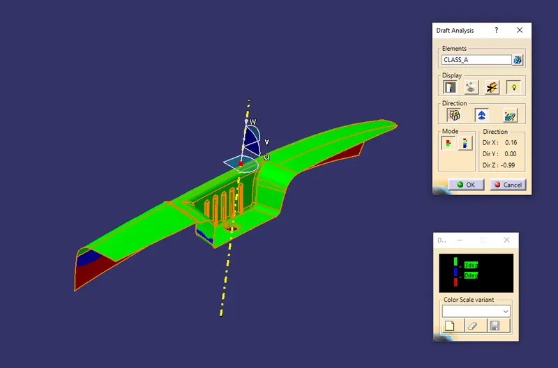
Draft Analysis:
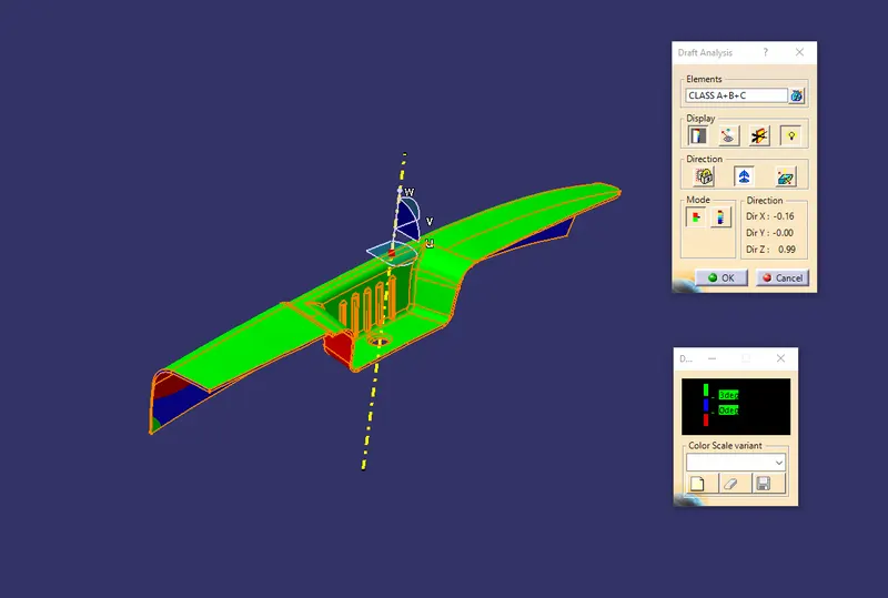
- To perform the draft analysis the view parameters are first set to material mode.
- Then go to Insert >>analysis>>feature draft analysis.
- First, select the axis system and drag the axis system to align and coincide with the tooling axis and lock the orientation. This axis system defines the draft direction according to the tooling axis.
- Switch on the color scale and set the minimum draft value. Here it is set to 3 degrees and it will be displayed in green color. Any draft angle below 3 degrees will be shown in red color.
- Here, the compass direction is rotated to have the positive direction in maximum portion of the part. Then the compass is locked in the orientation and a new tooling axis is created using the compass as the direction.
Class A:
Final Body:
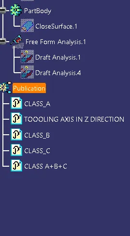
Tree Structure:
] 
Conclusion:
- Class A, B and C surface was created as per the automotive standards using catia v5software.
- Draft analysis was performed for the built model and it could be seen that the draft was under permissible limit for the manufacturing of the component.