Week 8:- 3D Finishing Challenge 2
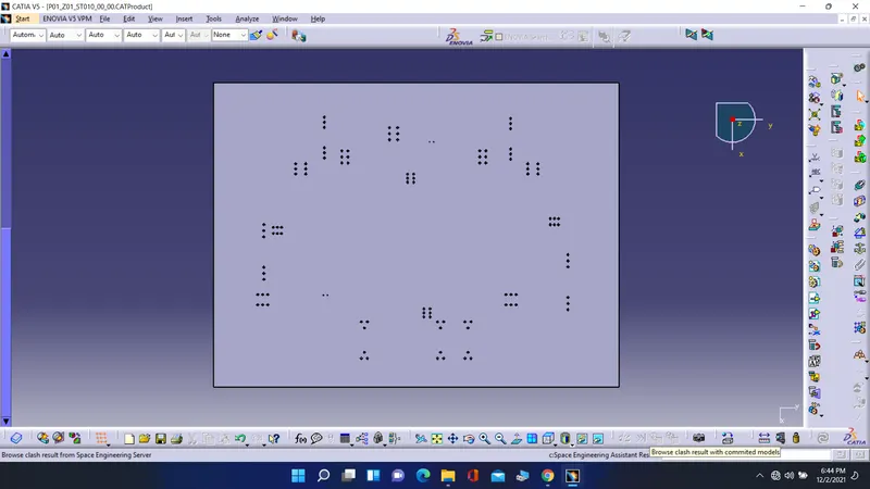
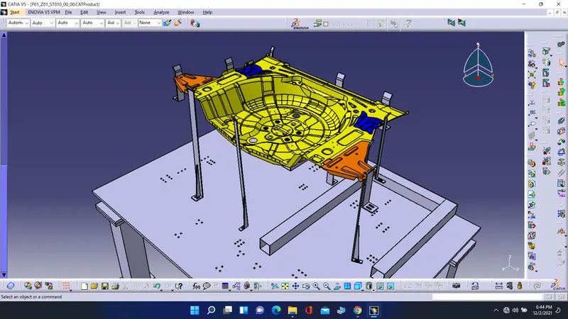
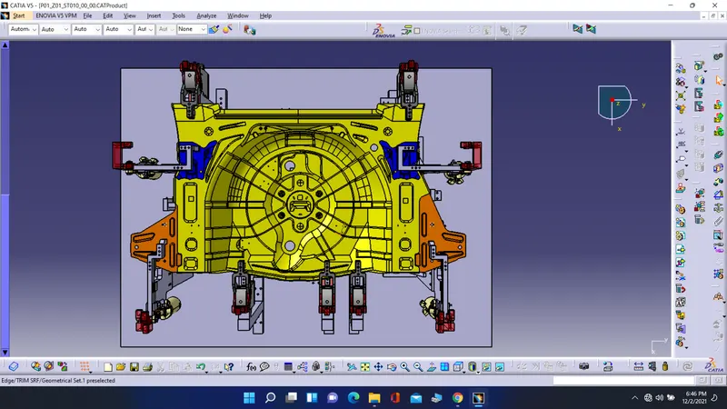
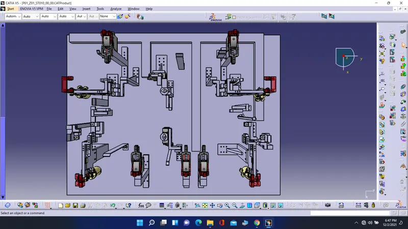
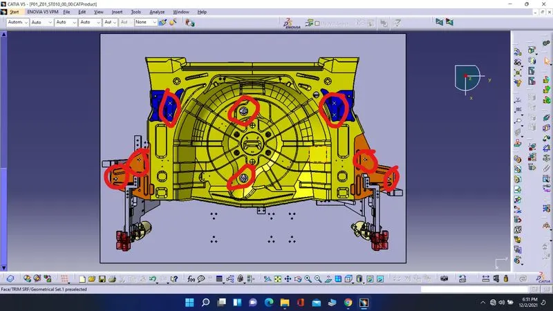
These are the following steps, which I followed to make this fixture design:-
- I created a part tree which parts I want to design this fixture. Like for fixed pin design we want a pin , pin retainer , shims, riser, block, and so on
- Second, I created a circular pin for fix pin unit and created a pin retainer. Then I created a block for the two way direction shims and then riser for fixed pin unit.
- The shims required two direction so the pin can move accordingly. To adjust the pin at the hole on the panel.
- The holes on the block, riser and retainer are required as two for fixed bolt and one is dowel hole.
- All the parts perfectly matching with each other so that I used snap tool to fix the par.
- For making the parts there are so many features used like pad, pocket, snap, manipulate, holes, circle, erase, line, and so on.
- Now for retractable pin unit there are different types of cylinder used to make pins.
- For one retractable pin I used diamond shaped pin and single rod cylinder. For this pin, we need risers and shims.
- For second one I used diamond shaped pin and double rod pin so if the next hole is next to one hole then we cannot use two-pin unit at same position. For this pin unit we need a pin retainer, block, riser and cylinder.
- Now, for the clamp unit first create a rest and clamp Mylar as required to the geometry.
- After that insert a clamp part from the design library and position it with clamp Mylar.
- Now create a riser to fit the clamp with the base plate.
- Design a clamp unit with following same steps on different position.
- Now we want to design a rest unit for same panel. For that, first create a rest Mylar and block to fix with riser.
- Now, create a riser, which is fix with a block.
- Again following with same steps, I created a rest unit for different position.
- For the swivel clamp unit we have to design two rest Mylar and two clamp Mylar for one clamp.
- After that, we have to design a clamp arm for the Mylar to stand by.
- In next step insert a cylinder from design library and position it as required. In addition, snap it with clamp arm.
- On the clamp arm we have to draw a through hole to move the cylinder and the hole size will be as bush size (18mm).
- Now create a blade to hold the rest Mylar, cylinder and fix with riser.
- On blade, draw a pivot point to hold the clamp arm and one point for the cylinder.
- Now create a riser with required length and I created L type riser.
- As mentioned in challenge I created a 3-swivel clamp unit on different positions.
- Now for pin clamp unit first design a pin, pin retainer, and block for it.
- Also, design a rest Mylar, clamp Mylar, clamp arm, and insert a cylinder.
- In addition, all the parts are rested on one rise. That is called as pin clamp unit.
- Now, for base unit first create a base plate on which all the unit can be fixed with required constraints.
- First, observe that there are any unit, which is clashing, which is other if happens than first required operations separate them with each other so they can fixed on the base plate. The tubes are on all around the base plate.
- Now, first create a square tube for the channel below the base plate.
- Now, on each corner create a plate for fixing with pedestal.
- Create a pedestal with square tubes and on bottom side of pedestal there is also a plate which is called as floor plate. Because it is fixed with a floor.
- 3D FINISHING PROCESS
- For 3D finishing there are some parameters we have to check with it.
- First the hole concentricity of all the parts and the sizes of the holes. The hole concentricity means the axis of the two holes must be in same line the difference between both axis must be zero in all X,Y, and Z coordinate.
- The machining are of the parts is where the machining is required like back side of the risers and L-Block.
- Nominality of the parts means with reference of base all the parts should not have distance in decimal form like 299.99, 28.950, or 786.896. it should must be in full digit like 300, 29, or 787.
- Holes colouring means the colour of the hole on basis of its size. Like threaded holes are is with yellow colour, dowell holes are in blue colour, open holes are in light green colour. So it is standard colours of the different sizes holes.
- Pneumatic layout means the space between the end of base plate and the end of the parts should be enough to plot a cable duct for pneumatic system.
- The gaps between all the parts close enough to fit the parts or must have enough space to assemble or disassemble the parts without any damage to other parts. And the implementation of the parts is fast.
- Clashing of the parts with each other should be avoid. Therefore, the design is good and easy.
- Mylars should be installed as per panel profile. Like the mylars can’t stay on holes or in between of two different panels. And the splitting of the mylars should be proper with reference the panel on which it is placed.
- Now the second step is rough locators. The rough locators guide the panel before the pin units. They are for the fix the panel before other units. Rough locators are can be installed on base plates or any other units riser.
- Valve banks are placed at side of the base plate on which the cable duct is connected and entire pneumatic system is handle from this.
- Sensors are required on the panel for inspecting the panel during the operation. and we can also inspect the panel on computer with help of sensors. We don’t required any physical interaction for checking the panel because of sensors.
- There are different types of sensors as per the requirement. Like proximity sensor is used for whether is object presence or not. Next is laser sensor used for check the distance with the help of laser. Like this so many sensors are available in market we can use them as requirement.
- Proper renaming of all the parts so the parts can easily identity and classified with it.
So, following these steps I completed the week 5 challenge.