Week 7 State of charge estimation
Battery Management System:
Battery management system (BMS) is an electronic system that manages a rechargeable battery (cell or Battery pack). such as by protecting the battery from operating outside its safe operating area, monitoring its state, calculating the data, reporting that data, controlling its environment, authenticiting, and balancing it.
The Main objective of the BMS is
- To protect the cells or the battery from damage.
- prolong the life of the battery.
- Maintain the battery in a state in which it can fulfill the functional requirements of the application for which it was specified.
Function of BMS:
- Cell Protection
- charge control
- SOC determination
- SOH determination
- cell balancing
- managing the system
- data logging
- communications
- Authentication and Identification.
Below is The Battery management system and Algorithm Testing
Dashboard
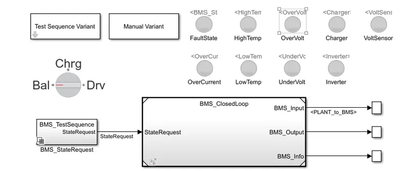
Closed loop Battery management system
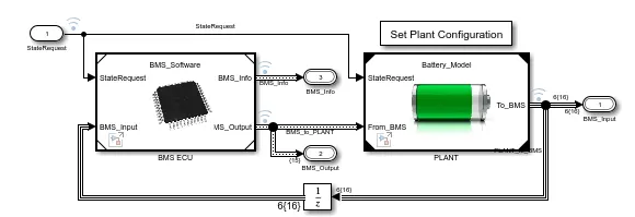
The BMS ClosedLoop consist of interlinking of the BMS and the plant (Battery pack). BMS ECU is the Heart of the system which controls all the progam, control algorithm and logics too.
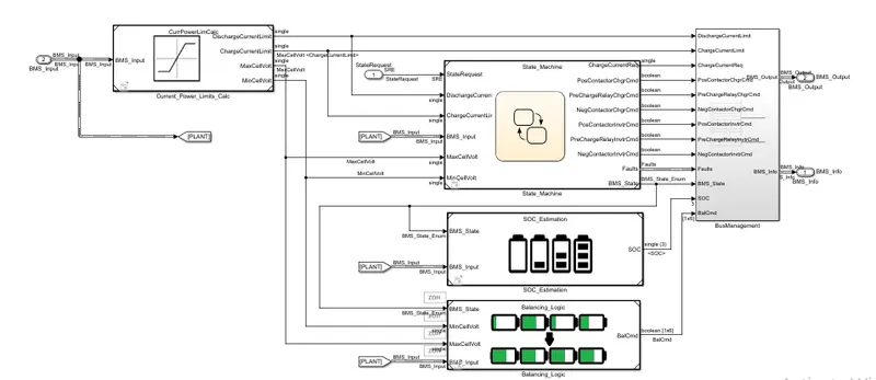
This is the entire system level design inside the BMS ECU. it has the following blocks in it:
- state machine
- SOC estimation
- Balancing Logic circuit
State machine block is responsible for implementing 3 logics namely:
- Driving characteristics.
- charging.
- Balancing.
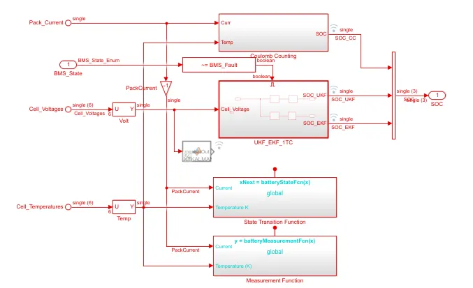
The SOC Estimation is the key important block in the BMS_ECU, which helps to determine the charge present in the cell at that time. State of chage estimation using extended kalman filter, coulomb counting and unscented kalman filter.
Kalman filtering is also known as linear quadratic estimation (LQE), is an algorithm that uses a series of measurement observed over time.
coulomb counting method measures the discharging current of a battery and integrates the discharging current over time in order to estimate the SOC. The following equation is used fo soc estimation.

SOC(t-1) = previous time step
`η`= efficiency
t= current time step
t-1 = previous time step
Q is the charge capacity of the Battery
This method is accurate and reliable than the voltage translational method but does not take into account of the discharge rate, temperature, hysteresis, age of battery etc.
The Test sequence variant has in build 3 modes.
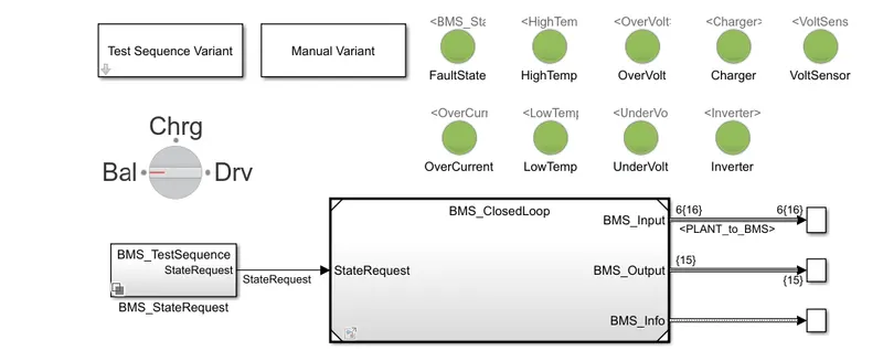
After debugging the model and running in each of the selected vaiant. below simulation is generated based on the test sequence input.
SCOPE1: Driving, charging and standby mode.
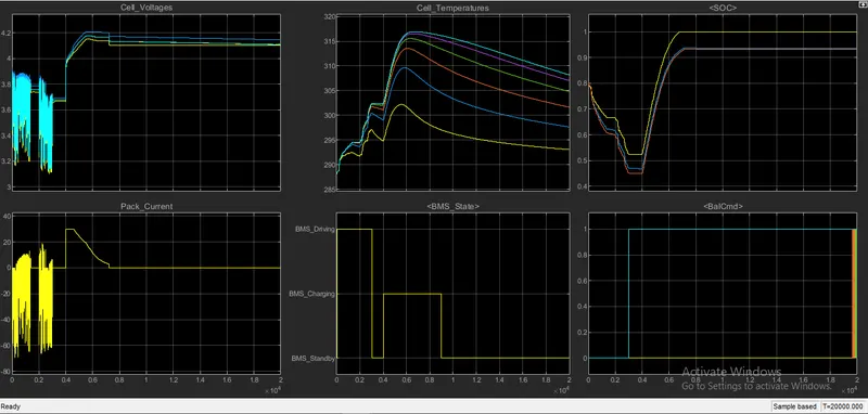
- The simulation is run for T=20000sec. Initially the vehicle is standby condition with soc 80%, then it is discharged which leads to reduction in soc from 80% to 45%. there is consumption of current which increase in cell temperature and reduction of cell voltage.
- after driving for few minutes the vehicle comes to standby mode, where all the value becomes stable.
- from Standby it jumps to charge state, where there is change in pack current, voltage and cell temperatures. after one cell reaches the soc 100% the BMS changes to standby mode.
SCOPE2: Discharge mode
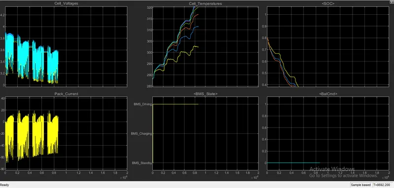
- The vehicle is in standby mode and after change request it goes to driving mode.
- The SOC is reduced from 80% to 0% due to continuous driving mode. there is cont change in cell voltage and current, with increases the cell temperature.
- due to soc reduced to 0% this cycle is 8692.200secs only driving mode.
scope 3: charging mode
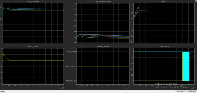
- The vehicle is charged from soc 80% to 100%. there is no other mode given. there is balancing happening in the charging mode.
- due to continuous charge current initially increases and decreases comes to 0A. while the voltage becomes after the current becomes zero.
There was no error found in 3 steps variant.