Project 1 Mechanical design of battery pack
Aim:
To prepare a detailed battery pack drawing along with its enclosure for the following specifications given
- using cell ANR26650M1-B
- Battery pack capacity 18Kwh
Introduction:
- Battery Pack:
A battery pack is a set of any number of identical batteries or individual battery cells. They may be configured in a series, parallel or a mixture of both to deliver the desired voltage, capacity, or power density
Components of battery packs include the individual cells or Modules, and the interconnections which provide electrical conductivity between them. Interconnections are also found in batteries as they are the part which connects each cell, though batteries are most often only arranged in series strings.
When a pack contains groups of cells in parallel there are differing wiring configurations which take into consideration the electrical balance of the circuit. Battery regulators are sometimes used to keep the voltage of each individual cell below its maximum value during charging so as to allow the weaker batteries to become fully charged, bringing the whole pack back into balance. Active balancing can also be performed by battery balancer devices which can shuttle energy from strong cells to weaker ones in real time for better balance. A well-balanced pack lasts longer and delivers better performance.
Rechargeable battery packs often contain a sensors, which the battery monitoring system uses to detect the Temperature, to monitor the voltage and control the battery pack operation.
For an inline package, cells are selected and stacked with solder in between them. The cells are pressed together and a current pulse generates heat to solder them together and to weld all physical connections internal to the cell.
Battery pack designing Process:
how is Capacity & Voltage determined?
With a simple series chain of cells, the battery capacity in Ampere-Hours is the same as the capacity of the individual cells since the current flows equally through all the cells in the chain.
High battery voltages are achieved by adding more cells in a series chain. The voltage of the battery is the voltage of a single cell multiplied by the number of cells in the chain. This does not
increase the Ampere-Hour capacity of the battery, but it increases the Watt-Hour capacity, or the total stored energy, in proportion to the number of cells in the chain. Battery capacity canbe increased through adding more parallel cells. This increases the Ampere-Hour capacity as well as the Watt-Hour capacity without increasing the battery voltage. For
batteries with parallel chains the capacity of the battery is the capacity of the individual chain multiplied by the number of parallel chains.
Whereas cell voltage is fixed by the cell chemistry, cell capacity depends on the surface area of the electrodes and the volume of the electrolyte, that is, the physical size of the cell. If at all possible, the number of cells in a pack should be minimised to simplify the design and to minimise potential reliability problems. Fewer cells require fewer support electronics. Thus, the parallel chains should be avoided by specifying the highest capacity cells available. Cells with different capacities or cell chemistries should not be mixed in a single battery pack.
Design of Battery Pack
The design of the outer package or housing of the battery depends to a great extent on the components it has to accommodate and the physical protection it has to provide for them. These components are not just the cells, but also protection devices, electronic circuits, interconnections and connectors which must all be specified before the final battery case can be designed. For high power, high energy batteries robust packaging is required for safety reasons. Its important for the performance of the Battery pack and for better lifetime of the battery.
The shape and dimensions of the battery pack are mostly governed by the cavity which is planned to house it within the intended application. This in turn dictates the possible cell sizes and layouts which can be used.
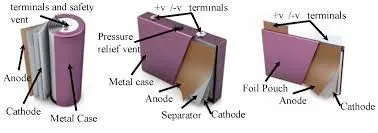
There are three types of cells that are used in lithium batteries – cylindrical, prismatic, and pouch cells. where they are selected based on the requirements. Prismatic cells provide the best space utilisation, however cylindrical cells provide simpler cooling options for high power batteries. The use of Pouch cells provides the product designer more freedom in specifying the shape of the battery cavity permitting very compact designs.
Electronic components:
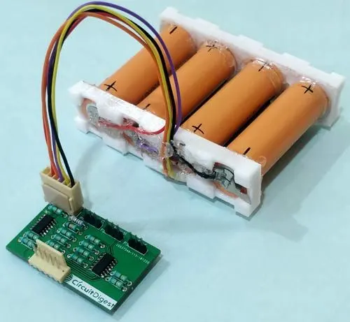
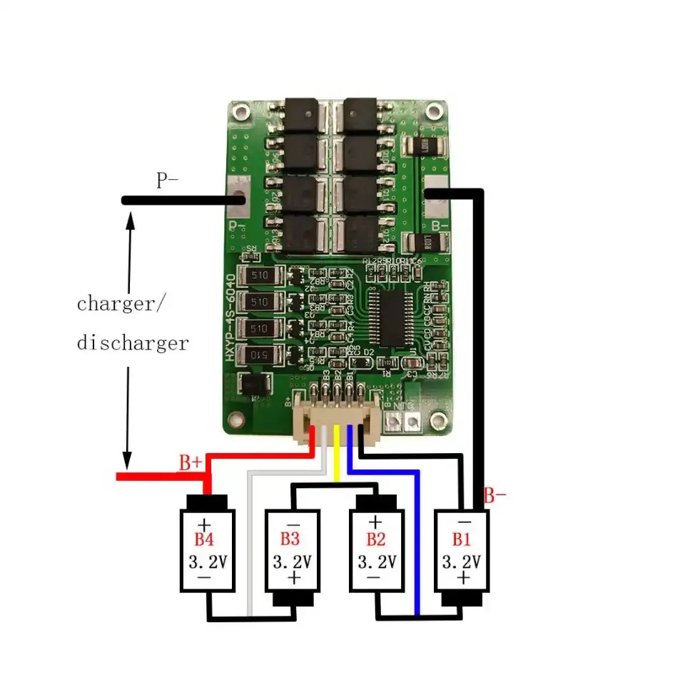
Besides the cells many battery packs now incorporate associated electronic circuits. These may be protection devices and circuits, monitoring circuits, charge controllers, fuel gauges, and
indicator lights. Electronics for high power multi-cell packs also include cell balancing and communications functions.The packs may also be designed to deliver more than one voltage from the basic cell combination, although applications requiring multiple voltage sources are more likely to make provision for this within the application. In addition to the basic battery support electronics the battery pack may include other functions such as heaters to extend the lower working temperature or solarcells to keep the battery fully charged. These circuits in turn have their own control circuits.

BMS Software
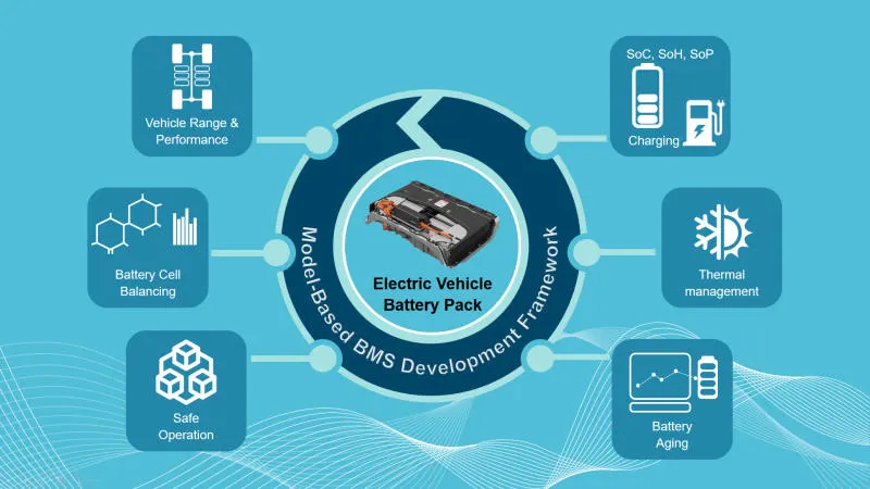
Software is a major component of Lithium batteries, particularly for automotive applications. Control systems are required to keep the cells within their specified operating range and to protect them from abuse. Communications with other vehicle systems are needed for monitoring the battery status and controlling energy flows.
Internal connections
Low power cells are usually connected together using nickel strips which are welded to the cell terminals or the case. Soldering is not recommended since the soldering process is apt to apply large, uncontrolled amounts of heat to the battery components which may damage the separators or the vents which are normally made of plastic. Modern computer-controlled resistance welders allow much more precise control of the welding process, both limiting the amount of heat applied to the battery and localising the heat to a small desired area. Welding also provides a stronger, low resistance joint. High power cells may use solid copper bus bars or braided straps. The electronic components are usually mounted on a conventional printed circuit board (PCB).
External connections:
The type of terminals or connections to the external circuits depend on, the current to be carried, the frequency with which the battery may be connected and disconnected and the design of the design of the circuit to which the battery will be connected. Flying leads with spade terminals or snap on studs are also used for low power applications. Metal tabs are also used on pouch cells.Terminals for high power applications are usually threaded metal studs to ensure a reliable connection. Safety requirements on high voltage batteries may also dictate shrouded terminals to prevent accidental exposure of the operator to dangerous voltages or of the battery to short circuits. Keyed or terminals or connections are also advisable to prevent connection to incorrect chargers or loads.
Thermal management is a major issue in high power designs, particularly for automotive applications. As part of the battery system, it may be necessary to provide air or water cooling ducts, pumps or fans and heat exchangers for high temperature working or heaters for operating in low temperature environments.
Packaging:
The battery casing has to provide the mechanical and electrical interfaces to the product it is designed to power as well as to contain all the components outlined above.The simplest and least expensive packaging for small batteries is shrink wrap or vacuum formed plastic. These solutions are only possible if the battery is intended to be completely enclosed by the finished product. The overall product cost can be further reduced by using insert moulding in which the interconnection strips and the terminals are moulded into the plastic parts to eliminate both materials and assembly costs. Over moulding may also be used to encapsulate and protect small components or sub-assemblies.
Identifications:
The pack design must incorporate some form of identification to indicate the manufacturer's name, the cell chemistry, the voltage and the capacity as well as the country of manufacture. Most manufacturers will also include a date stamp and or serial number to assist traceability in case of problems. This information is usually provided on a label but it may also be printed directly on to the battery casing
Cell specifications:
ANR26650M1-B - Nanophosphate High Power Lithium-Ion Cell
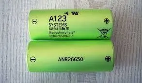
ANR26650M1-B Specifications
Nominal Ratings
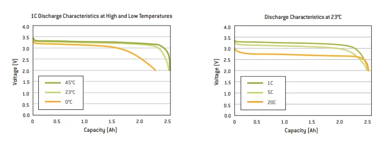
Voltage: 3.3 Volts
Capacity: 2.5 Ah
Energy: 8.25 Wh
Specific Power: 2600 W/kg
Impedance (1KHz AC Typical) 6 mΩ
Cycle Life at 1C/1C, 100% DOD: > 4000 cycles
Cell Type: 26650 Lithium Ion Power Cylindrical Cell
Discharging
Max Continuous Discharage: 50 A
Max Pulse Discharge Current >50% SOC (10s): 120 A
Minimum Voltage: 2 Volts
Temperature: -30ºC to 55ºC
Charging
Recommended Standard Charge: 2.5 Amps
Max Charge Rate: 10 Amps
Max Pulse Charge Current <50% SOC (10s): 25 A
Float Voltage: 3.45 Volts
Recommended charge V & Cut-off Current: 3.6 Volts, taper to 125mA
Temperature
(reduce charging current to 250mA when under 0ºC): 0ºC to 55ºC
Mechanical
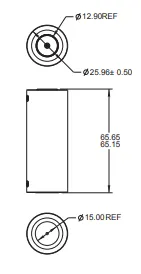
Diameter: Ø25.96 +/- 0.5 mm (1.0")
Length: 65.15 +/- 0.5 mm (2.6")
Mass: 76 g
Certifications
Transportation: UN 3480 (UN38.3), CIQ
Safety: UL 1642, IEC 62133
The LithiumWerks ANR26650M1-B is the next generation of A123 Systems’ pioneering 26650 cylindrical cell, now with greater power and energy density and lower impedance. This versatile lithium ion cell is suitable for a wide variety of applications and system designs. Proven performance in the toughest conditions, combining durability, reliability, and safety, the ANR26650 cell offers an excellent combination of price-performance.
- Battery pack calculations:
cell configuration:
Required battery energy capacity: 18Kwh
Assuming the total voltage of the pack has 330V.
𝐁𝐚𝐭𝐭𝐞𝐫𝐲 𝐂𝐚𝐩𝐚𝐜𝐢𝐭𝐲 (𝐀𝐡) =𝐁𝐚𝐭𝐭𝐞𝐫𝐲 𝐄𝐧𝐞𝐫𝐠𝐲 𝐂𝐚𝐩𝐚𝐜𝐢𝐭𝐲 (𝐖𝐡)/𝐁𝐚𝐭𝐭𝐞𝐫𝐲 𝐏𝐚𝐜𝐤 𝐍𝐨𝐦𝐢𝐧𝐚𝐥 𝐕𝐨𝐥𝐭𝐚𝐠𝐞 (𝐕)
Ah= (18*10^3)/330 =54.54 ~ 55Ah
To Calculate the total no of cells used need to calculate the no of cells in series and parallel.
XS= Battery pack voltage/ nominal cell voltage= 330/3.3= 100 cells are in series.
XP= Battery pack capacity Ah/ cell Nominal capacity Ah= 55/2.5= 22 cells are in parallel connections.
𝐓𝐨𝐭𝐚𝐥 𝐍𝐨 𝐨𝐟 𝐜𝐞𝐥𝐥𝐬 𝐢𝐧 𝐁𝐚𝐭𝐭𝐞𝐫𝐲 𝐩𝐚𝐜𝐤 = 𝐍𝐨 𝐨𝐟 𝐜𝐞𝐥𝐥𝐬 𝐢𝐧 𝐬𝐞𝐫𝐢𝐞𝐬 × 𝐍𝐨 𝐨𝐟 𝐜𝐞𝐥𝐥𝐬 𝐢𝐧 𝐩𝐚𝐫𝐚𝐥𝐥𝐞𝐥
Total no of cells in battery pack = 100*22 = 2200 cells are used for 18Kwh battery pack.
Therefore, the battery configuration is 100S22P
Mechanical constructions:
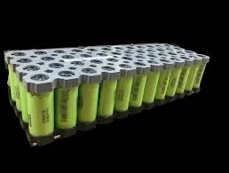
Assuming the clearance between the cells is 2mm.
𝐋𝐞𝐧𝐠𝐭𝐡 (𝐥) = (𝐍𝐨 𝐨𝐟 𝐜𝐞𝐥𝐥𝐬 𝐢𝐧 𝐬𝐞𝐫𝐢𝐞𝐬 × 𝐃𝐢𝐚𝐦𝐞𝐭𝐞𝐫 𝐨𝐟 𝐚 𝐜𝐞𝐥𝐥) + ((𝐍𝐨 𝐨𝐟 𝐜𝐞𝐥𝐥𝐬 𝐢𝐧 𝐬𝐞𝐫𝐢𝐞𝐬 + 𝟏) ×𝐜𝐥𝐞𝐚𝐫𝐚𝐧𝐜𝐞 𝐛𝐞𝐭𝐰𝐞𝐞𝐧 𝐭𝐡𝐞 𝐜𝐞𝐥𝐥𝐬)
Length (l) = (100*25.96)+((100+1)*2) = 2596+202 = 2798 mm
Estimated width of the Battery cells with holder,
𝐖𝐢𝐝𝐭𝐡 (𝒘) = (𝐍𝐨 𝐨𝐟 𝐜𝐞𝐥𝐥𝐬 𝐢𝐧 𝐩𝐚𝐫𝐚𝐥𝐥𝐞𝐥 × 𝐃𝐢𝐚𝐦𝐞𝐭𝐞𝐫 𝐨𝐟 𝐜𝐞𝐥𝐥𝐬) + ((𝐍𝐨 𝐨𝐟 𝐜𝐞𝐥𝐥𝐬 𝐢𝐧 𝐩𝐚𝐫𝐚𝐥𝐥𝐞𝐥 +𝟏) × 𝐜𝐥𝐞𝐚𝐫𝐚𝐧𝐜𝐞 𝐛𝐞𝐭𝐰𝐞𝐞𝐧 𝐭𝐡𝐞 𝐜𝐞𝐥𝐥𝐬)
Width (w) = (22*25.96)+((22+1)*2) = 571.12+46 = 617.12 =~618 mm
Estimated Height of the Battery cells with holder,
𝐇𝐞𝐢𝐠𝐡𝐭 (𝒉) = 𝐇𝐞𝐢𝐠𝐡𝐭 𝐨𝐟 𝐭𝐡𝐞 𝐜𝐞𝐥𝐥
Height (h) = 65.15 =~66 mm
Inner Dimension of the Enclosure:
Estimated inner Length of the Battery pack,
𝐋𝐞𝐧𝐠𝐭𝐡 (𝐋𝐢) = 𝐋𝐞𝐧𝐠𝐭𝐡 𝐨𝐟 𝐭𝐡𝐞 𝐁𝐚𝐭𝐭𝐞𝐫𝐲 𝐜𝐞𝐥𝐥𝐬 𝐰𝐢𝐭𝐡 𝐡𝐨𝐥𝐝𝐞𝐫 (𝐥) + 𝐒𝐩𝐚𝐜𝐞 𝐟𝐨𝐫 𝐚𝐜𝐞𝐬𝐬𝐨𝐫𝐢𝐞𝐬 + 𝐨𝐭𝐡𝐞𝐫 𝐟𝐚𝐜𝐭𝐨𝐫𝐬
Let assume, the space for the other accessories like BMS, Contactors, Balancing circuit is
approximately 50mm and for other factors (Thermal spacing, gap for swelling) is 5mm
Length (Li) = 2798+50+5 = 2853 mm
Estimated inner width of the Battery Pack,
𝐖𝐢𝐝𝐭𝐡 (𝐖𝐢) = 𝐖𝐢𝐝𝐭𝐡 𝐨𝐟 𝐭𝐡𝐞 𝐁𝐚𝐭𝐭𝐞𝐫𝐲 𝐂𝐞𝐥𝐥 𝐰𝐢𝐭𝐡 𝐡𝐨𝐥𝐝𝐞𝐫 (𝐰) + 𝐨𝐭𝐡𝐞𝐫 𝐟𝐚𝐜𝐭𝐨𝐫𝐬
Width (Wi) = 618+5 = 622.12 =~623mm
Estimated inner Height of the Battery Pack,
𝐇𝐞𝐢𝐠𝐡𝐭 (𝑯𝒊) = 𝐇𝐞𝐢𝐠𝐡𝐭 𝐨𝐟 𝐭𝐡𝐞 𝐁𝐚𝐭𝐭𝐞𝐫𝐲 𝐜𝐞𝐥𝐥 𝐰𝐢𝐭𝐡 𝐡𝐨𝐥𝐝𝐞𝐫 (𝐡) + 𝐨𝐭𝐡𝐞𝐫 𝐟𝐚𝐜𝐭𝐨𝐫𝐬
Height (Hi) = 66+5 =~71mm
Therefore, Inner dimensions of the battery pack is 2853 X 623 X 71 mm
Outer Dimensions of the Battery pack:
Considering the enclosure material as 5mm Al 6061,
Estimated outer length of the Battery pack,
𝐋𝐞𝐧𝐠𝐭𝐡(𝑳𝟎) = 𝐥𝐞𝐧𝐠𝐭𝐡 𝐨𝐟 𝐭𝐡𝐞 𝐁𝐚𝐭𝐭𝐞𝐫𝐲 𝐩𝐚𝐜𝐤(𝑳𝑰) + (𝐄𝐧𝐜𝐥𝐨𝐬𝐮𝐫𝐞 𝐦𝐚𝐭𝐞𝐫𝐢𝐚𝐥 𝐭𝐡𝐢𝐜𝐤𝐧𝐞𝐬𝐬 × 𝟐)
Length (Lo) = 2853+(2*5) = 2863 mm
As the enclosure is made up of the sheet metal, the manufacturing tolerance to be considered as 1mm,
Length (Lo) = 2863±1 mm
Estimated outer width of the Battery pack,
𝐖𝐢𝐝𝐭𝐡(𝑾𝒐) = 𝐰𝐢𝐝𝐭𝐡 𝐨𝐟 𝐭𝐡𝐞 𝐁𝐚𝐭𝐭𝐞𝐫𝐲 𝐩𝐚𝐜𝐤(𝑾𝒊) + (𝐄𝐧𝐜𝐥𝐨𝐬𝐮𝐫𝐞 𝐦𝐚𝐭𝐞𝐫𝐢𝐚𝐥 𝐓𝐡𝐢𝐜𝐤𝐧𝐞𝐬𝐬 × 𝟐)
Width (Wo) = 623+(2*5) = 633 mm
Width (Wo) = 633±1 mm
Estimated outer height of the Battery Pack,
𝐇𝐞𝐢𝐠𝐡𝐭(𝑯𝒐) = 𝐡𝐞𝐢𝐠𝐡𝐭 𝐨𝐟 𝐭𝐡𝐞 𝐁𝐚𝐭𝐭𝐞𝐫𝐲 𝐩𝐚𝐜𝐤(𝑯𝒊) + (𝐄𝐧𝐜𝐥𝐨𝐬𝐮𝐫𝐞 𝐦𝐚𝐭𝐞𝐫𝐢𝐚𝐥 𝐓𝐡𝐢𝐜𝐤𝐧𝐞𝐬𝐬 × 𝟐)
Height (Ho) = 71+(2*5) = 81 mm
Height (Ho) = 81±1 mm
Therefore, the outer dimensions of the enclosure is (2863±1)X(633±1)X(81±1) mm
Mass of the Battery Pack:
𝐌𝐚𝐬𝐬 (𝐌) = (𝐓𝐨𝐭𝐚𝐥 𝐧𝐨 𝐨𝐟 𝐜𝐞𝐥𝐥𝐬 × 𝐌𝐚𝐬𝐬 𝐨𝐟 𝐚 𝐜𝐞𝐥𝐥) + 𝐌𝐚𝐬𝐬 𝐨𝐟 𝐭𝐡𝐞 𝐚𝐜𝐜𝐞𝐬𝐬𝐨𝐫𝐢𝐞𝐬
Let assume, Mass of the accessories as 1kg, (including BMS, Contactors, Electrical Connectors (both interconnections and external connectors)).
Mass (M) = (2200*76) + 1000 = 167200+1000 = 168200 g = 168.2 kg = ~169kg
Therefore, the mass of the battery pack is 169 kg.
Specific energy of the Battery Pack:𝐒𝐩𝐞𝐜𝐢𝐟𝐢𝐜 𝐄𝐧𝐞𝐫𝐠𝐲 𝐃𝐞𝐧𝐬𝐢𝐭𝐲 =𝐏𝐚𝐜𝐤 𝐄𝐧𝐞𝐫𝐠𝐲 𝐂𝐚𝐩𝐚𝐜𝐢𝐭𝐲 𝐢𝐧 𝐖𝐚𝐭𝐭−𝐇𝐨𝐮𝐫𝐌𝐚𝐬𝐬 𝐨𝐟 𝐭𝐡𝐞 𝐁𝐚𝐭𝐭𝐞𝐫𝐲 𝐏𝐚𝐜𝐤 𝐢𝐧 𝐊𝐢𝐥𝐨𝐠𝐫𝐚𝐦
Specific Energy Density = (18*103)/169 = 106.50 Wh/kg
Volumetric Energy Density of the Battery Pack:
𝐕𝐨𝐥𝐮𝐦𝐞𝐭𝐫𝐢𝐜 𝐄𝐧𝐞𝐫𝐠𝐲 𝐃𝐞𝐧𝐬𝐢𝐭𝐲 =𝐏𝐚𝐜𝐤 𝐄𝐧𝐞𝐫𝐠𝐲 𝐂𝐚𝐩𝐜𝐢𝐭𝐲 𝐢𝐧 𝐖𝐚𝐭𝐭−𝐇𝐨𝐮𝐫𝐕𝐨𝐥𝐮𝐦𝐞 𝐨𝐟 𝐛𝐚𝐭𝐭𝐞𝐫𝐲 𝐩𝐚𝐜𝐤 𝐢𝐧 𝐥𝐢𝐭𝐫𝐞𝐬
𝐕𝐨𝐥𝐮𝐦𝐞 𝐨𝐟 𝐭𝐡𝐞 𝐁𝐚𝐭𝐭𝐞𝐫𝐲 𝐏𝐚𝐜𝐤 = 𝐋𝐞𝐧𝐠𝐭𝐡 𝐨𝐟 𝐭𝐡𝐞 𝐁𝐚𝐭𝐭𝐞𝐫𝐲 𝐏𝐚𝐜𝐤 × 𝐖𝐢𝐝𝐭𝐡 𝐨𝐟 𝐭𝐡𝐞 𝐁𝐚𝐭𝐭𝐞𝐫𝐲 𝐏𝐚𝐜𝐤 ×𝐇𝐞𝐢𝐠𝐡𝐭 𝐨𝐟 𝐭𝐡𝐞 𝐁𝐚𝐭𝐭𝐞𝐫𝐲 𝐏𝐚𝐜𝐤
Volume of the Battery Pack = 2863*633*81 = 14,67,94,599 mm^3
𝟏 𝒎^𝟑 = 𝟏 × 𝟏𝟎𝟗𝒎𝒎^𝟑
Volume of the Battery Pack in m3 = 14,67,94,599*10-9 = 0.15 cubic metre
𝟏𝒎𝟑 = 𝟏𝟎𝟎𝟎 𝑳𝒊𝒕𝒓𝒆𝒔
Volume of Battery Pack in Litres = 0.15*1000 = 150 litres
Volumetric Energy Density = (18*103)/150 = 120 Wh/l
Mass of the Enclosure:
𝑴𝒂𝒔𝒔 = 𝑽𝒐𝒍𝒖𝒎𝒆 × 𝑫𝒆𝒏𝒔𝒊𝒕𝒚
Volume of the Enclosure (Ve) = Volume of the Battery pack(Vo) – Inner volume of the Battery Pack(Vi)
Volume of the Enclosure (Ve) = 0.15 – ((2853*623*71)*10-9) = 0.15 – 0.13 = 0.02 m3
Since, Al 6061 material is used, Density is 2.7 g/cm3.
Mass of the Enclosure = (0.02*106)*2.7 = 20000*2.7 = 54000g = 54kg.
Result:
Thus a detailed battery pack drawing along with its enclosure for the following specifications given are done
- using cell ANR26650M1-B
- Battery pack capacity 18Kwh