Week 7 State of charge estimation
SOC Estimation - Using Simulink BMS Harness Dashboard
Objective:
- Part1 - To understand the BMS (Battery Management System) working and to simulate the BMS model in Simulink harness dashboard for various test cases and studying the variation in SOC, Temperature and Voltage
- Part2 - Coulomb counting method understanding - To calculate the SOC (State of Charge)
Part 1 - Simulating BMS closed loop harness dashboard model test.
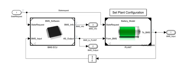
BMS Closed Loop Model:
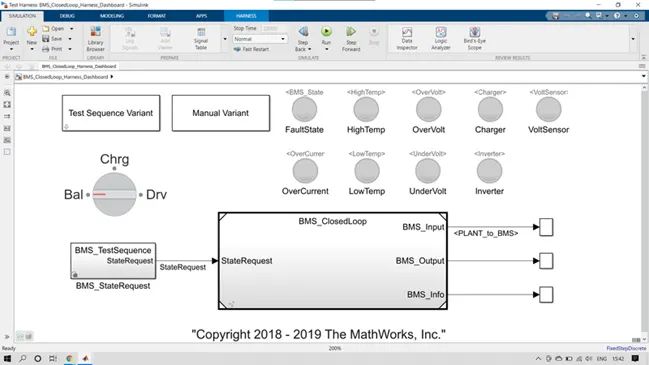
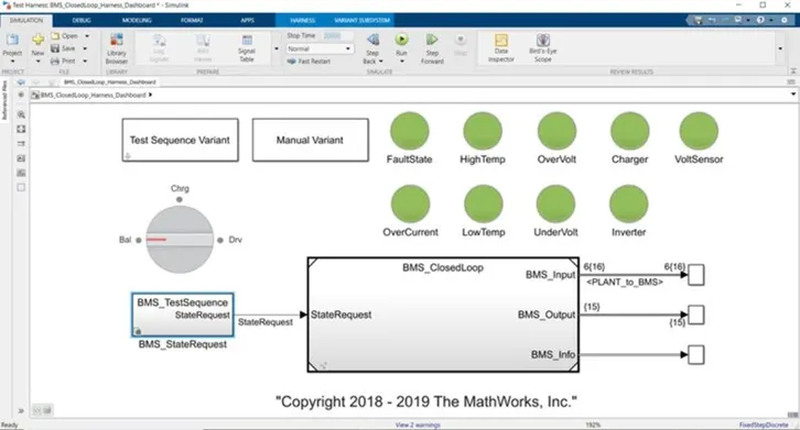
Harness Dashboard Model:
Model Description:
We can use this model for desktop simulations where we can reproduce diverse usage cycles and environmental conditions to evaluate the system’s response to a potentially unsafe condition; for example, a temperature, voltage, or current outside the recommended limits.
Simulation Procedure:
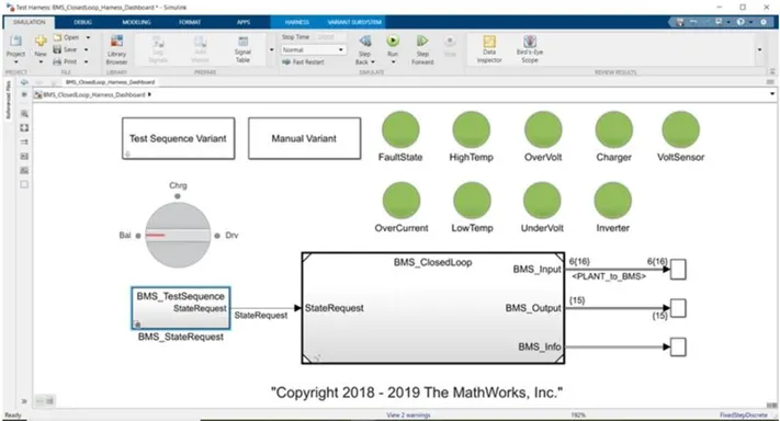
- There are Test sequence variant and Manual Variant. We need to run 'Test Sequence Variant'.
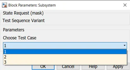
- Test Sequence Variant subsystem have three test cases, we can select case 1,2 ,3 from the drop-down list.
- Default Time is 20000 s for all test cases.
Outputs are Cell voltage, Temperature, SOC, and other battery balance and states.
1stTest Case:
Sequence mode:
- Driving state (0-3000 secs)
- Balancing State (3000-4000 secs)
- Charging and Balancing state (4000- 9000 sec)
- Post charge Balancing state (9000- 20000sec)
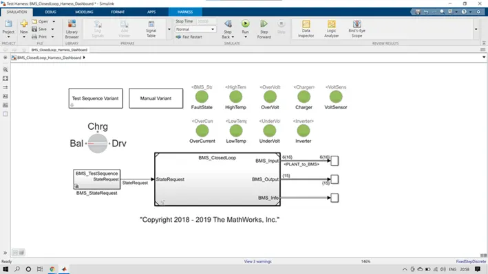
Dashboard results:
After simulation the dashboard indicators are all Green – no issues in model
SCOPE:
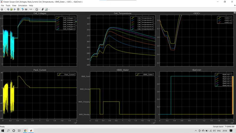
Driving state:
- All the cells for the first 3000 secs are in driving state so the discharge of all the cells occurs and its varies in the range of 3.1 to 3.9 V (min and max.).
- Cell temperature increases from 288K to 302 K.
- SOC reduces from 80 % to 45%.
Balancing State:
- From 3000sec to 4000 secs, cell balancing occurs and the Modules are in standby mode and they are having constant voltage of 3.7V.
- During balancing no current flow so cell temperature reduces.
- SOC is 45% and constant.
Charging and Balancing state:
- After 4000 sec the charging occurs and the cell voltages increased from 3.7 to nearly about 4.2 V in Constant current mode with current of nearly 30A and then the constant voltage charging starts and current reduces from 30A to 2.5 A Charging and balancing of cells occur till 9000 sec.
- SOC increases from 45% to 94%.
Post charge Balancing state (9000- 20000sec):
- After 9000 sec the post cell balancing starts under standby mode.
- Cell temperature reaches the ambient temperature.
- SOC remains constant to 94%.
2ndTest Case:
Sequence mode:
- Driving State (10000 secs).
- Charging state to (20000 secs).
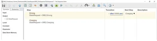
Dashboard results:
All dashboard indicators are green and no fault is occurred.
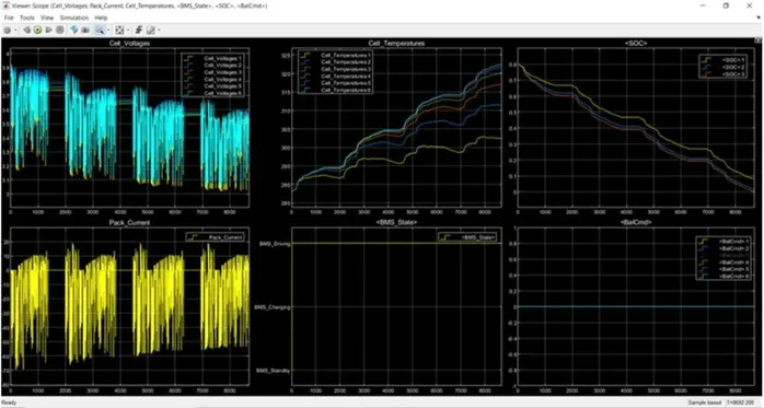
SCOPE:
Observations:
- cell voltage varies from 3.9 V to 3.05 volt.
- Cell temperatures rises from 288K to 323K.
- SOC reduces from 80% to 0%.
- Balancing of cells are not performed
3rdTest Case:
Sequence mode:
- Only Charging state (0-20000 sec):

Dashboard results:
All the indicator were green model is in good condition and no fault is occurred.
Scope:
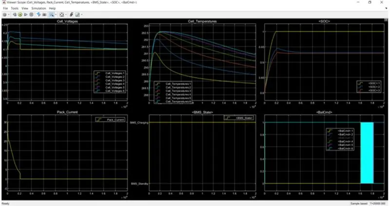
Observations:
- This test case entire battery pack sequence is operating in charging mode.
- Cell Voltages increases initially and become constant .
- Pack current were 0 to 30A and
- SOC is 80% ,after 2000 sec it got fully charged up to 100%.
- Cell temperature starts to increases initially and when battery got fully charged then decrease down to the ambient temperature.
- Balancing done automatically.
Conclusion:
All the three test sequences of BMS system are simulated and analysed through harness dashboard.
PART - 2
Coulomb Counting Method:
The coulomb counting method is also known as the battery current integration method. In this method, a discharging/charging current I(t) is measured and integrated over time to calculate the amount of energy remaining inside the battery. In this method, SOC is taken at the previous time step SOC(t-1) and the amount of energy removed/added at the current time step is subtracted/added from the SOC of the previous time step SOC(t-1) to obtain the amount of energy present in the battery at the present instant.
The SOC estimation in the coulomb counting method is done using the below equation,
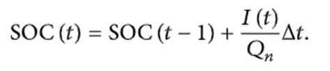
SOC(t-1) = SOC at previous time step
t = current time step
t-1 = previous time step
Q = Charge capacity of the battery
This method is accurate and reliable than the voltage translational method but does not take into account the discharge rate, temperature, hysteresis, age of the battery, etc.