Week 7 State of charge estimation
Simulate the 3 test cases from the harness dashboard and write a detailed report on the results:
To simulate the test cases, you can follow the instructions in the file exchange link provided and use the BMS model to run the simulations. The test cases are designed to evaluate the BMS performance under different conditions, such as constant current discharge, variable current discharge, and voltage sensing. To write a detailed report on the results, you should analyze the simulation data and compare the expected and actual results for different metrics, such as voltage, current, temperature, and SOC. You can also discuss the limitations and trade-offs of the BMS design and suggest possible improvements or modifications based on the simulation results.
open Matlab and make the current folder the folder having the BMS project
open the battery system. prj it will open the BMS project
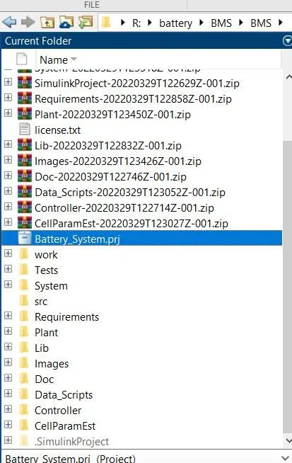
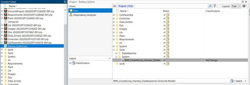
select Tests > system > BMS closed loop harness dashboard
it will open the Simulink model of BMS closed-loop dashboard
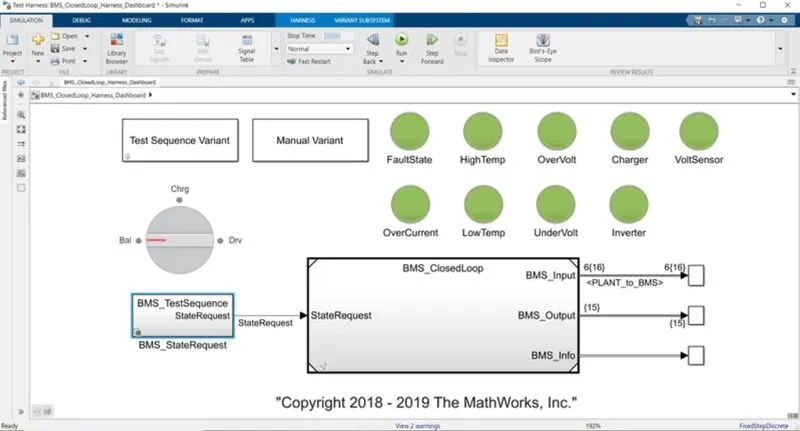
BMS CLOSED LOOP HARNESS DASHBOARD:
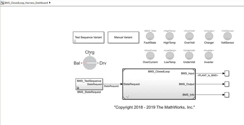
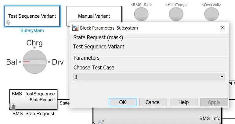
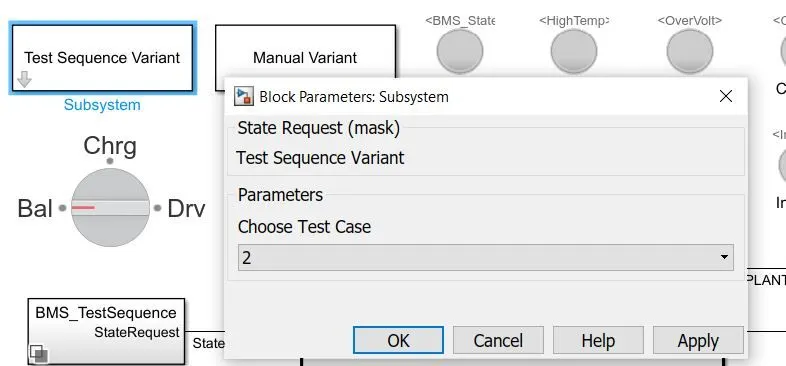
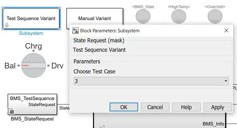
It contains subsystem 1 - Test sequence variant which contains the 3 test sequences, the test sequence needed can be selected in this subsystem.
Subsystem 2 - it is a manual variant, if this block is active, we have to select the test sequence manually by using a rotary switch which has 3 conditions battery, charging, and driving.
BMS state request is the subsystem which is the request input to the BMS closed loop which gives which test sequence is selected whether it is an automatic test sequence or a manually selected sequence.
It contains indicator light lamps of fault state, High Temp, Overvoltage, Charger, Voltage Sensor, Overcurrent, Low temp, Under Voltage, and Inverter state of a battery.
Greenlight is the good condition of the battery, red light indicates the bad or faulty condition of the battery system.
BMS CLOSED LOOP:
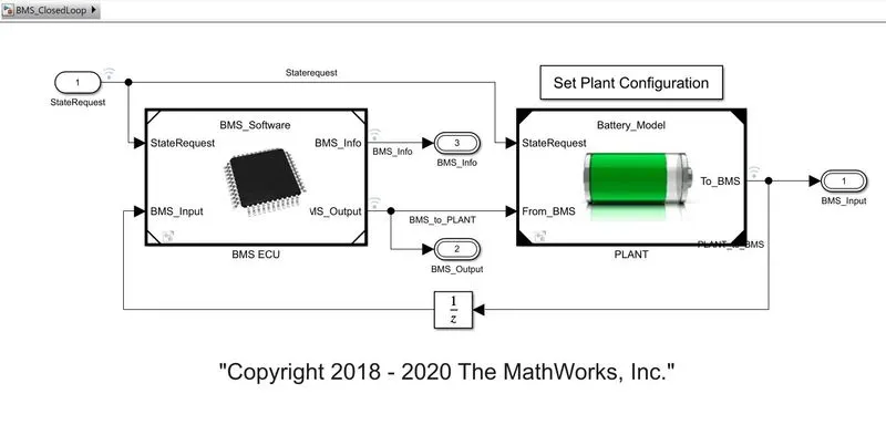
The closed loop consists of two subsystems BMS ECU and Plant
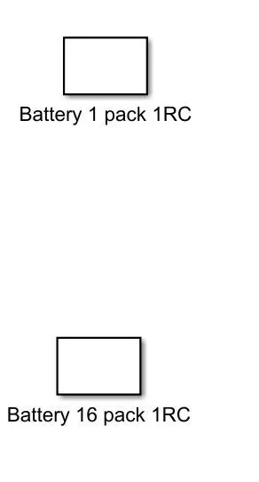
The battery plant has two configurations of 1 module and 16 modules of battery which can be selected by a set plant configuration block.
BMS ECU:
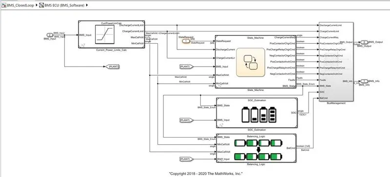
BMS ECU is the software-like unit that controls, protects, balances, and manages the battery,
It consists of subsystems
current power limits calculation - This block controls and calculates the charge current limit, and discharge current limit. In voltage of cell and max voltage of the cell.
state machine - This is the state machine, which gets the input from the state request, based on the state request state machine goes through the logic of charging, discharging, and balancing by opening the contactors of the battery, and inverter and monitoring the fault states and give the BMS output.
SOC estimation - SOC is accurately estimated by coulomb counting and using the Kalman filters,
Balancing logic - This is the subsystem that consists of a state machine that will balance the cell according to the BMS state, it will activate balancing or deactivate the balancing according to the BMS state requirements.
PLANT:
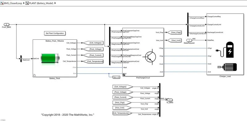
Battey pack - consists of the cell with some configurations of voltage and capacity.
Recharge circuit - It is used to limit the Inrush current to slowly charge the downstream capacitance.
Charger and Load - charger subsystems with controlled current source which charge the battery according to the BMS state and the drive load subsystem consists of load requirements of the drive cycle which draws the current and discharges the battery according to the load.
After the compilation is successful the scope opens up. The scope consists of the measurements of cell voltages, cell temperatures, SOC, pack current, BMS State, and Balancing command.
Task - 1:
1. Simulate the 3 test cases from the harness dashboard and write a detailed report on the results
TEST CASE - 1
Procedure:
Select the test sequence variant as 1 and inside the BMS state request subsystem the test sequence 1 is selected.
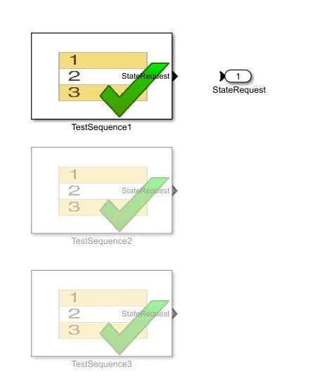
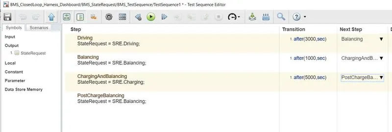
double click on the test sequence it will open the sequence editor as shown below
- Driving state for the first 3000 sec.
- Then after the driving state Balancing of cells occurs for the next 1000 secs duration.
- After the balancing Charging and balancing occur for the next 5000 secs
- Post Charge Balancing occurs after 9000sec till 20000 secs simulation end time.
Results of case 1:
Test sequence 1
Dashboard results:
The Lamp indication was green for all states which means the model is in good condition and no fault occurs.

Scope of test sequence 1:
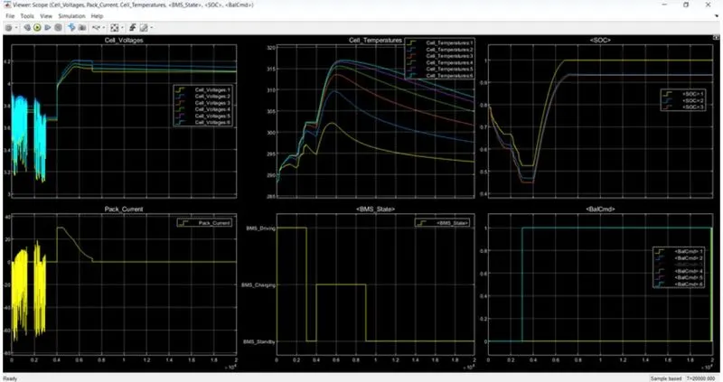
Observations:
Driving state (0-3000 secs):
- All the cells for the first 3000 secs are in a driving state so the discharge of all the cells occurs and it varies in the range of 3.1 to 3.9 V (min and max.).
- Cell temperature increases from 288K to 302 K.
- SOC also reduces from 80 % to 45%.
Balancing State (3000-4000 secs):
- After 3000sec for 1000 secs, cell balancing occurs and the Modules are in standby mode and they are having constant voltage near about 3.7V.
- Cell temperature reduces slowly as no current flows through the cells during balancing.
- SOC is also constant during this period at 45%.
Charging and Balancing state (4000- 9000 sec):
- after 4000 sec the charging occurs and the cell voltages increased from 3.7 to nearly about 4.2 V in Constant current mode with a current of nearly 30A then the constant voltage charging starts and the current reduces from 30A to 2.5 A Charging and balancing of cells occur till 9000 sec.
- Cell temperature also starts to increase exponentially up to the constant current region and reduces as current flow reduces in constant voltage mode.
- SOC also increases from 45% to 94%.
Post charge Balancing state (9000- 20000sec):
- After 9000 sec the post-cell balancing starts under standby mode.
- Cell temperature reduces in this mode and tries to reach the ambient temperature.
- SOC remains constant at 94%.
TEST CASE - 2
Procedure:
Select the test sequence variant as 2 and inside the BMS state request subsystem test sequence 2 is selected.
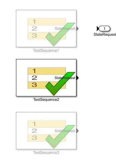
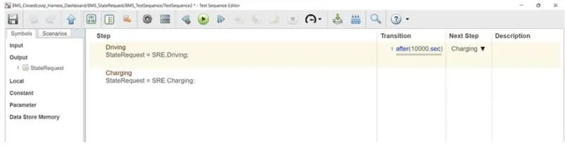
double click on the test sequence it will open the sequence editor as shown below
- Driving state for first 10000 secs.
- Then Charging state for the next 10000 secs.
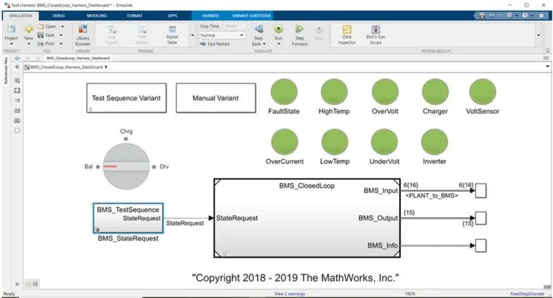
Results of case 2:
Test sequence 2
Dashboard results:
The Lamp indication was green for all states which means the model is in good condition and no fault occurs.
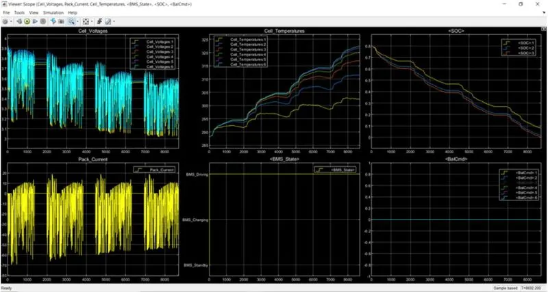
scope of test sequence 2:
Observations:
Driving State (0-10000 sec):
- The cell voltage varies from 3.9 V to 3.05 volt which is the cut-off voltage of the cell and the entire cell is drained up to 8692 sec.
- Cell temperatures vary from 288K to 323K.
- SOC reduces from 80% to 0% (cell got fully drained) in the drive mode under 8692 sec.
- Some stand-by mode conditions are in between the drive modes.
- The entire sequence is performed in drive mode as shown in the above plot.
- balancing of cells is not performed as shown as balance states are in 0 for the entire drive mode.
TEST CASE - 3
Procedure:
Select the test sequence variant as 3 and inside the BMS state request subsystem test sequence 3 is selected.
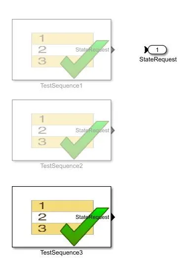
double click on the test sequence it will open the sequence editor as shown below
- Charging state for the entire simulation time.

Results of case 3:
Test sequence 3:
Dashboard results:
The Lamp indication was green for all states which means the model is in good condition and no fault occurs.
scope of test sequence 3:
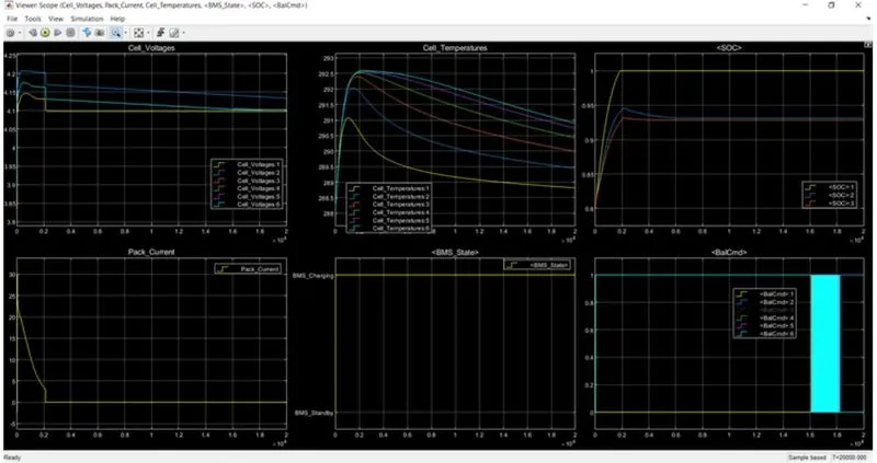
Observations:
Charging state (0-20000 sec):
- Cell Voltages increase from their initial values and after 2000 sec they become constant.
- Pack current initially starts from 0 to 30A and then starts decreasing when the constant voltage mode is there to 2.5 A and got fully charged up to 2000 sec.
- SOC was initially 80% and in 2000 sec it got fully charged, that is 100%.
- Cell temperature starts to increase initially and when the battery gets fully charged then decreases down to the ambient temperature.
-
The entire battery pack sequence is operating in charging mode as shown above.
- Balancing of all cells is done at the end of the simulation.
Conclusion:
All three test sequences of battery management systems are simulated and analyzed for various characteristics and results are plotted and observed.
What is coulomb counting? Refer to the above model and explain how BMS implements coulomb counting for SOC estimation.
Coulomb counting is a method of estimating the SOC of a battery based on the measurement of the charge or discharge current over time. The basic idea is that the total amount of charge that has entered or left the battery is proportional to the SOC, assuming no losses or inefficiencies. In the BMS model, coulomb counting is implemented by measuring the current flowing in and out of the battery and integrating it over time to obtain the accumulated charge. This charge is then divided by the battery capacity to estimate the SOC. However, coulomb counting is subject to errors and uncertainties due to various factors, such as temperature effects, voltage sag, aging, and parasitic losses, which can affect the accuracy and reliability of the SOC estimation.
How does the Lithium-Ion battery model in the above-linked file simulate the battery dynamics, including the voltage, current, temperature, and state of charge (SOC)? Can you explain the battery model equations and the assumptions underlying the battery behavior in different operating conditions?
The battery model in the BMS file uses an equivalent circuit model (ECM) to represent the electrical and thermal behavior of the battery. The ECM consists of a voltage source in series with a resistor, a capacitor, and a second resistor in parallel with a second capacitor. The voltage source represents the open circuit voltage (OCV) of the battery, which depends on the SOC and the temperature. The first resistor and capacitor represent the internal resistance and capacitance of the battery, which affect the voltage and current dynamics during charge and discharge. The second resistor and capacitor represent the surface effects and the diffusion process at the electrode-electrolyte interfaces, which affect the polarization and hysteresis effects of the battery. The battery model equations are based on Kirchhoff's laws and the Butler-Volmer equation, which describes the electrochemical reactions and the ion transport in the battery. The assumptions underlying the battery behavior in different operating conditions include the linearity and time-invariance of the battery model, the homogeneity and isotropy of the electrode materials, the absence of external heat sources or sinks, and the validity of the thermodynamic and kinetic models used to describe the battery chemistry and physics.
SOC: SOC stands for the state of charge of a battery. SOC represents the amount of energy left inside the battery with respect to the total amount of energy in a battery at the Fully charged condition. SOC can help a user determine when to charge the battery or stop charging and how much energy he can extract from a battery at that time. There is no direct method to calculate SOC for a Li-ion battery but there are several ways in which we can calculate SOC with the help of some additional parameters.
The easiest method to calculate the SOC of a battery is by using a battery voltage translation method. This method is not accurate but helps to approximately and quickly calculate SOC and can be used in devices like power banks where SOC is shown in range and not the exact percentage. For example, a typical power bank shows SOC in the range of 0-25%, 25-50%, 50-75%, and 75-100%.
There are several limitations to this method and hence more accurate methods are needed like the Coulomb counting method, the Fuzzy logic method, the Kalman filter, the RBF Neural network, the Fuzzy neural network, the Hybrid methods, etc.
Each method has its limitations, accuracy, and complexity and hence proper decision should be made while selecting methods for SOC estimation.
Coulomb counting:
Coulomb counting is a technique used to track the state of charge of a battery pack. It works by integrating the active flowing current (measured in amps) over time to derive the total sum of energy entering or leaving the battery pack. This produces a capacity that is typically measured in Ah.
Coulomb Counting Method:
The coulomb counting method is also known as the battery current integration method. In this method, a discharging/charging current I(t) is measured and integrated over time to calculate the amount of energy remaining inside the battery. In this method, SOC is taken at the previous time step SOC(t-1) and the amount of energy removed/added at the current time step is subtracted/added from the SOC of the previous time step SOC(t-1) to obtain the amount of energy present in the battery at the present instant.
The SOC estimation in the coulomb counting method is done using the below equation,
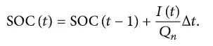
SOC(t-1) = SOC at the previous time step
t = current time step
t-1 = previous time step
Q = Charge capacity of the battery
This method is more accurate and more reliable than the voltage translational method but does not take into account the discharge rate, temperature, hysteresis, age of the battery, etc.
Coulomb counting block in BMS:
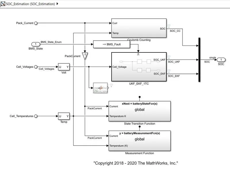
soc estimation block:
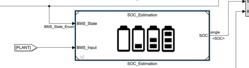
Here soc is estimated by
i) Coulomb counting method
ii) Unscented Kalman filter
iii) Extended Laman filter.
Coulomb counting method:
This block implements the above-mentioned soc equation to estimate the SOC.
In this method, a discharging/charging current I(t) is measured and integrated over time to calculate the amount of energy remaining inside the battery.
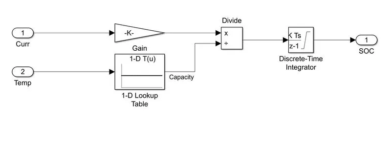
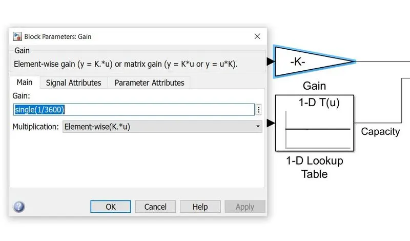
The gain value is given as 1/3600 to convert the current in A to Ah.
Discrete-time integrator block and its configuration:
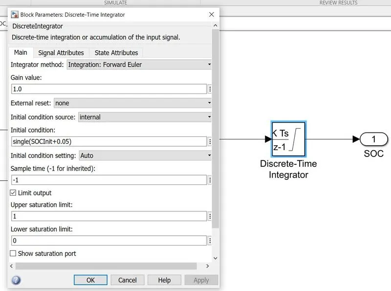
Thus, the BMS system implements the SOC equation using the above blocks to estimate the SOC.
CONCLUSION:
The battery management system project model is downloaded and initialized in MATLAB and it is simulated for the 3 test sequences.
All three test sequences of battery management systems are simulated and analyzed for various characteristics and results are plotted and observed.
The coulomb counting method is studied and the implementation of that method is BMS to estimate the SOC is analyzed.
What are the challenges and limitations of lithium-ion battery management systems (BMS), and how can they be addressed in future designs? Can you suggest some novel approaches or technologies that can improve the accuracy, safety, and efficiency of BMS?
There are several challenges and limitations of lithium-ion battery management systems (BMS). Some of them are:
Accurate State of Charge (SOC) estimation: The SOC estimation of the battery is essential for its optimal performance and longevity. However, it is challenging to estimate the SOC accurately due to the nonlinear behavior of the battery and its dependence on various factors such as temperature, aging, and current rate.
Thermal management: The temperature of the battery is a crucial factor that affects its performance, safety, and life. BMS must ensure that the battery operates within a safe temperature range by monitoring and controlling the temperature of the cells.
Safety concerns: Lithium-ion batteries are prone to thermal runaway and can catch fire or explode if not managed properly. BMS must incorporate safety features such as overcharge and over-discharge protection, short-circuit protection, and thermal management to prevent accidents.
Complexity and cost: BMS comprises several components such as sensors, microcontrollers, communication interfaces, and software algorithms. The complexity and cost of these components make the BMS expensive and challenging to design and manufacture.
To address these challenges and limitations, some novel approaches and technologies that can improve the accuracy, safety, and efficiency of BMS are:
Advanced algorithms for SOC estimation: Advanced machine learning and artificial intelligence algorithms can be used to estimate the SOC accurately, taking into account various factors such as temperature, aging, and current rate.
Thermal management: Innovative cooling systems such as phase change materials, liquid cooling, and air cooling can be used to maintain the temperature of the battery within a safe range.
Smart BMS: Smart BMS can monitor and control the battery's performance, safety, and life in real time by collecting data from various sensors and optimizing the charging and discharging cycles accordingly.
Integration of wireless technology: Wireless communication technology such as Bluetooth, Wi-Fi, and cellular can be integrated into BMS to provide remote monitoring and control of the battery.
Material innovations: Novel materials such as solid-state electrolytes, silicon anodes, and graphene can improve the performance, safety, and life of lithium-ion batteries, and hence the BMS.
Overall, the development of innovative technologies and approaches can address the challenges and limitations of BMS, making them more accurate, safe, and efficient.