Week 7 State of charge estimation
Answer:1.
Battery management system
A battery management system (BMS) is any electronic system that manages a rechargeable battery (cell or battery pack), such as by protecting the battery from operating outside its safe operating area, monitoring its state, calculating secondary data, reporting that data, controlling its environment, authenticating it and / or balancing it.
A battery pack built together with a battery management system with an external communication data bus is a smart battery pack. A smart battery pack must be charged by a smart battery charger.
Functions
Monitor
A BMS may monitor the state of the battery as represented by various items, such as:
- Voltage: total voltage, voltages of individual cells, or voltage of periodic taps
- Temperature: average temperature, coolant intake temperature, coolant output temperature, or temperatures of individual cells
- Coolant flow: for liquid cooled batteries
- Current: current in or out of the battery
- Health of individual cells
- State of balance of cells
Electric vehicle systems: energy recovery
- The BMS will also control the recharging of the battery by redirecting the recovered energy (i.e., from regenerative braking) back into the battery pack (typically composed of a number of battery modules, each composed of a number of cells).
Battery thermal management systems can be either passive or active, and the cooling medium can either be air, liquid, or some form of phase change. Air cooling is advantageous in its simplicity. Such systems can be passive, relying only on the convection of the surrounding air, or active, using fans for airflow. Commercially, the Honda Insight and Toyota Prius both use active air cooling of their battery systems. The major disadvantage of air cooling is its inefficiency. Large amounts of power must be used to operate the cooling mechanism, far more than active liquid cooling.The additional components of the cooling mechanism also add weight to the BMS, reducing the efficiency of batteries used for transportation.
Liquid cooling has a higher natural cooling potential than air cooling as liquid coolants tend to have higher thermal conductivities than air. The batteries can either be directly submerged in the coolant or coolant can flow through the BMS without directly contacting the battery. Indirect cooling has the potential to create large thermal gradients across the BMS due to the increased length of the cooling channels. This can be reduced by pumping the coolant faster through the system, creating a tradeoff between pumping speed and thermal consistency.[3]
Computation
Additionally, a BMS may calculate values based on the below items, such as:
- Voltage: minimum and maximum cell voltage
- State of charge (SoC) or depth of discharge (DoD), to indicate the charge level of the battery
- State of health (SoH), a variously-defined measurement of the remaining capacity of the battery as % of the original capacity
- State of power (SoP), the amount of power available for a defined time interval given the current power usage, temperature and other conditions
- State of Safety (SOS)
- Maximum charge current as a charge current limit (CCL)
- Maximum discharge current as a discharge current limit (DCL)
- Energy [kWh] delivered since last charge or charge cycle
- Internal impedance of a cell (to determine open circuit voltage)
- Charge [Ah] delivered or stored (sometimes this feature is called Coulomb counter)
- Total energy delivered since first use
- Total operating time since first use
- Total number of cycles
- Temperature Monitoring
- Coolant flow for air or liquid cooled batteries
Communication
The central controller of a BMS communicates internally with its hardware operating at a cell level, or externally with high level hardware such as laptops or an HMI.
High level external communication are simple and use several methods:
- Different types of serial communications.
- CAN bus communications, commonly used in automotive environments.
- Different types of wireless communications.
Low voltage centralized BMSes mostly do not have any internal communications.
Distributed or modular BMSes must use some low level internal cell-controller (Modular architecture) or controller-controller (Distributed architecture) communication. These types of communications are difficult, especially for high voltage systems. The problem is voltage shift between cells. The first cell ground signal may be hundreds of volts higher than the other cell ground signal. Apart from software protocols, there are two known ways of hardware communication for voltage shifting systems, optical-isolator and wireless communication. Another restriction for internal communications is the maximum number of cells. For modular architecture most hardware is limited to maximum 255 nodes. For high voltage systems the seeking time of all cells is another restriction, limiting minimum bus speeds and losing some hardware options. Cost of modular systems is important, because it may be comparable to the cell price. Combination of hardware and software restrictions results in a few options for internal communication:
- Isolated serial communications
- wireless serial communications
To bypass power limitations of existing USB cables due to heat from electrical current, communication protocols implemented in mobile phone chargers for negotiating an elevated voltage have been developed, the most widely used of which are Qualcomm Quick Charge and MediaTek Pump Express. "VOOC" by Oppo (also branded as "Dash Charge" with "OnePlus") increases the current instead of voltage with the aim to reduce heat produced in the device from internally converting an elevated voltage down to the battery's terminal charging voltage, which however makes it incompatible with existing USB cables and relies on special high-current USB cables with accordingly thicker copper wires. More recently, the USB Power Delivery standard aims for an universal negotiation protocol across devices of up to 240 watts.
Protection
A BMS may protect its battery by preventing it from operating outside its safe operating area, such as:
- Over-charging
- Over-discharging
- Over-current during charging
- Over-current during discharge
- Over-voltage during charging, especially important for lead–acid, Li-ion and LiFePO4 cells
- Under-voltage during discharging, especially important for Li-ion and LiFePO4 cells
- Over-temperature
- Charging while under low temperature
- Over-pressure (NiMH batteries)
- Ground fault or leakage current detection (system monitoring that the high voltage battery is electrically disconnected from any conductive object touchable to use like vehicle body)
The BMS may prevent operation outside the battery's safe operating area by:
- Including an internal switch (such as a relay or mosfet) which is opened if the battery is operated outside its safe operating area
- Requesting the devices to which the battery is connected to reduce or even stop using or charging the battery.
- Actively controlling the environment, such as through heaters, fans, air conditioning or liquid cooling
Battery connection to load circuit
A BMS may also feature a precharge system allowing a safe way to connect the battery to different loads and eliminating the excessive inrush currents to load capacitors.
The connection to loads is normally controlled through electromagnetic relays called contactors. The precharge circuit can be either power resistors connected in series with the loads until the capacitors are charged. Alternatively, a switched mode power supply connected in parallel to loads can be used to charge the voltage of the load circuit up to a level close enough to battery voltage in order to allow closing the contactors between battery and load circuit. A BMS may have a circuit that can check whether a relay is already closed before precharging (due to welding for example) to prevent inrush currents to occur.
Balancing
In order to maximize the battery's capacity, and to prevent localized under-charging or over-charging, the BMS may actively ensure that all the cells that compose the battery are kept at the same voltage or State of Charge, through balancing. The BMS can balance the cells by:
- Wasting energy from the most charged cells by connecting them to a load (such as through passive regulators)
- Shuffling energy from the most charged cells to the least charged cells (balancers)
- Reducing the charging current to a sufficiently low level that will not damage fully charged cells, while less charged cells may continue to charge (does not apply to Lithium chemistry cells)
Topologies
BMS technology varies in complexity and performance:
- Simple passive regulators achieve balancing across batteries or cells by bypassing charging current when the cell's voltage reaches a certain level. The cell voltage is a poor indicator of the cell's SoC (and for certain lithium chemistries, such as LiFePO
4, it is no indicator at all), thus, making cell voltages equal using passive regulators does not balance SoC, which is the goal of a BMS. Therefore, such devices, while certainly beneficial, have severe limitations in their effectiveness. - Active regulators intelligently turning on and off a load when appropriate, again to achieve balancing. If only the cell voltage is used as a parameter to enable the active regulators, the same constraints noted above for passive regulators apply.
- A complete BMS also reports the state of the battery to a display, and protects the battery.
BMS topologies fall in three categories:
- Centralized: a single controller is connected to the battery cells through a multitude of wires
- Distributed: a BMS board is installed at each cell, with just a single communication cable between the battery and a controller
- Modular: a few controllers, each handling a certain number of cells, with communication between the controllers
Centralized BMSs are most economical, least expandable, and are plagued by a multitude of wires. Distributed BMSs are the most expensive, simplest to install, and offer the cleanest assembly. Modular BMSes offer a compromise of the features and problems of the other two topologies.
The requirements for a BMS in mobile applications (such as electric vehicles) and stationary applications (like stand-by UPSes in a server room) are quite different, especially from the space and weight constraint requirements, so the hardware and software implementations must be tailored to the specific use. In the case of electric or hybrid vehicles, the BMS is only a subsystem and cannot work as a stand-alone device. It must communicate with at least a charger (or charging infrastructure), a load, thermal management and emergency shutdown subsystems. Therefore, in a good vehicle design the BMS is tightly integrated with those subsystems. Some small mobile applications (such as medical equipment carts, motorized wheelchairs, scooters, and fork lifts) often have external charging hardware, however the on-board BMS must still have tight design integration with the external charger.
Various battery balancing methods are in use, some of them based on state of charge theory.
The simulink for the Battery Management system is pasted below.
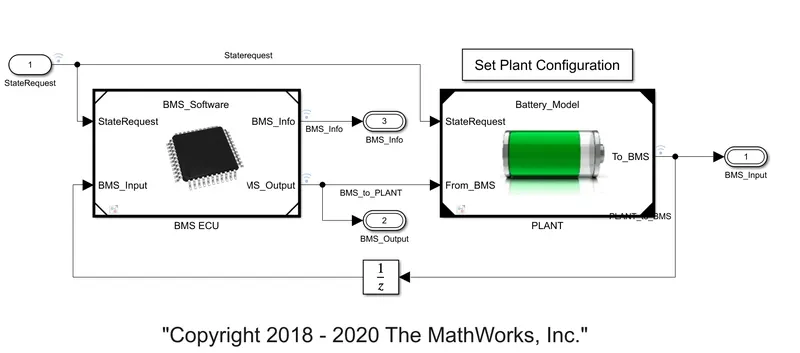
The Model is has 2 different plants which is nothing but the
1.Battery Management system ECU unit
2.Plant
The program is runned by means of the three differnet conditons.
The following condition are mentioned in detail below.
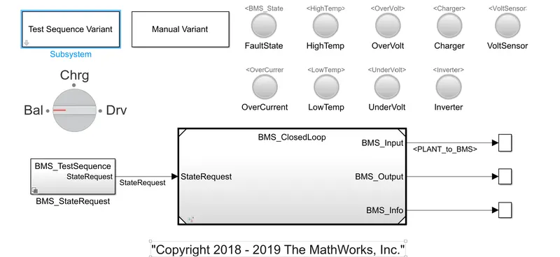
1.Test case 1: Discharging,Charging and Balancing / At BMS Level Test Condition For Both Driving & Charging
The program is runned and the following output is presented below.
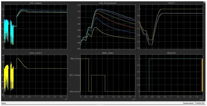
Detailed information of the plots has been explained below.
Cell voltage
- At the start there is Rise and fall of the voltage from the range of 3.8 to 3.2V by which the vehicle is in the driving condition. After 0.4s we can see the Rise of the volatage beyond the varying range
and comes to 4.2v which is maximum limit of the volatage which is obtained due to charging of the battery at that particular time period.
Pack Current
The pack current shows the discharge of the current from the battery, At the start we can see that there is variation from the 10A to -50A.During the negative region we can get the battery getting charged and the standby section is the place where All the systems are in neutral. After the time period of 0.4s the battery is kept for the section by which the current rises from the 0 to 30A and therer is a constant current 0.5s and it drops as it may have reached the maximum limit so the constant voltage is carried out after that and slowly it drops to 0.
Cell Temperature
There are 6 different which represents the different batteries and there temperature, At the start the temperature is used to rise from 280 to 315 which is during the operating conditon, And after 0.4s we can see the fall which is due to charging of the battery,which means there is no charges going out by which the heat is not produced.
BMS state
It is used to show the various paramaters happening in the system of bms
- From 0s to 0.3s the battery is discharging which is the driving conditon
- from 0.3 to 0.4s it is in standby condition, where there is no movement
- from 0.4 to 0.9s the battery is charging conditon,
- At last it is kept in the the standby conditon since the battery is fully charged
Soc
The Soc is used to show the amount of charge present in the battery, In this plot we can see the soc of the 6 differernt batteries. During the initial condition the battery is 90% which is fallen to 50% during the driving condition and comes back to 100% due to charging in the end.
Battery commad
It is used to show the command it is used to follow from the Bms.
Test case 2: Disharging and No Balancing / At BMS Level Test Condition For Driving
The following output of this test is given below.
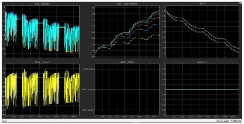
Cell Voltage
The voltage is continously being varied from 3.5 v to 3.1 v at the start and as we can see that there is continously discharge of the battery and at the the vehicle will be stopped due to the no charge availabe in the battery. And at the end the volatage is fully dropped to 2.8V. There is some stops within the intervals where the vehicle will be in the idle conditon and there are 4 intervals
Pack Current
The pack current is used to show the amount of electrons being passed out of battery or within the battery, so there is contionus discharge in the battery where it is from -70A to 9A at the end of the cycle. There is also some recharege which is done and also 4 different standby condition is availabe where the vehicle is in the idle condition
Cell Temperature
The cell Temperature is Rised to its Maximum at the end which is from the 289 to 324 at the end and the Strongest cell is used to fall at 299C
BMS state
- Since it is contionus driving state the shows the continous discharge conditon throughout the cycle
Soc
In this state the vehicle is being throughout the long range untill the charge is dropped to 0.so It is used to drop at 0 at 8500s
Battery Command
Since only discharge is happening throughout the cycle there is no command to the battery.
Test case 3: Charging and Balancing / At BMS Level Test Condition For Charging
The output plot for this Test is pasted below.
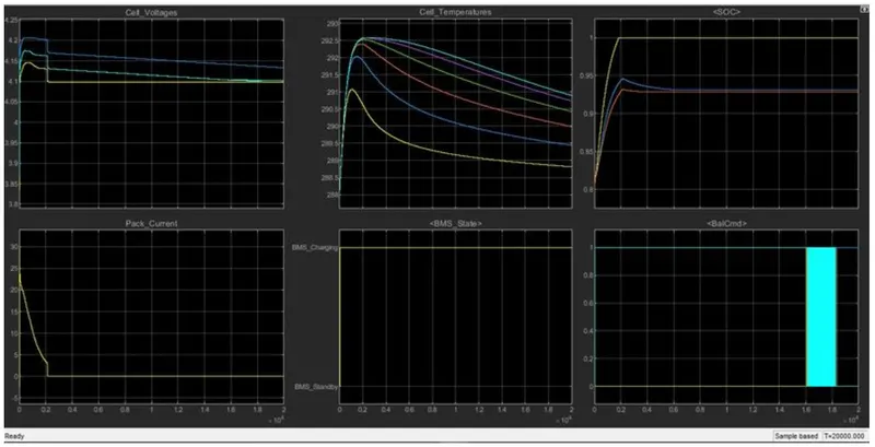
Cell Voltage
The volatage is used to rise from 4.1v to 4.2v during the period of 0.2s during to CC and it settles to 4.15 at the end by means of the constant volatage at the end.
Pack Current
The pack current drops from 24A to the 0 and there is constant current in the 0.2s and then the supply is stopped at end due to the battery is charged.
Cell Temperature
The cell temperature is rised since it is getting charged and drops gradually at the end.
BMS state
The Bms state is used to show various operation happening and it is used to control
- From the start to 0.2s It is in the charging conditon
- After then it is in the standby conditon which is mistaken in the graph, As we can see that the battery is fully charged before 0.2s itself so it is kept in the stand by conditon,
Soc
THe initial soc is 80% and after 0.2s it is fully Charged
Battery command
It is showing the value of the battery command which is from 0 to 1.
Answer:2
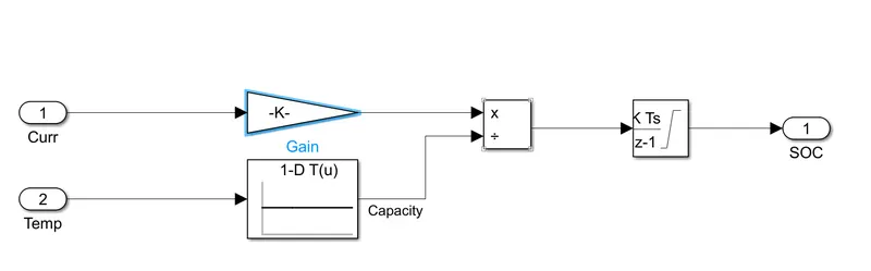
- Coulomb is used for the measurement of amount of charge present in the system
- For one charge it is represented as 1 coulomb
- But we need it over a period of time which by integreating it by means of time we can get it.
C.d/dt= C.t=Cs Amp
Now it is presented for the seconds, but we need it in terms of hours, and the time being integrated which is represented by dividing it by 3600 by which we can get it in Amps per hour
For the Soc which is nothing but showing the amount of charges available which is obtained by the above formula
Soc = present charge/ Total charge capacity