Week 7 State of charge estimation
Week-7 Challenge
Aim: To estimate state of charge of a battery
Objectives:
- Simulate the 3 test cases from harness dashboard and write a detailed report on the results
- What is coulomb counting? Refer to the above model and explain how BMS implements coulomb counting for SOC estimation?
Solution:
The model under consideration in this challenge is a project that deals with the designing and testing of the BMS structure of a lithium-ion battery. Project includes Simulink models for BMS Algorithms such as:
- State of Charge estimation using Extended Kalman Filter, Unscented Kalman Filter
- Passive Battery Cell Balancing
- State Machine for Pre-charging and Contactor Management
- Fault Management - Over/Under Voltage, Over Current, Over Temperature etc.
- Charge and Discharge Current Limit Calculations
To design and test these algorithms, project also includes files for
- Li-ion Battery Cell Parameter Estimation
- Battery Pack with 6 cells in series and 96 cells in series
- Simulink Test files with test cases to test State Machine Logic
- Linking requirements to Models
Our concern would be to just understand the SoC estimation for our challenge. The model for the state of charge estimation is built as:
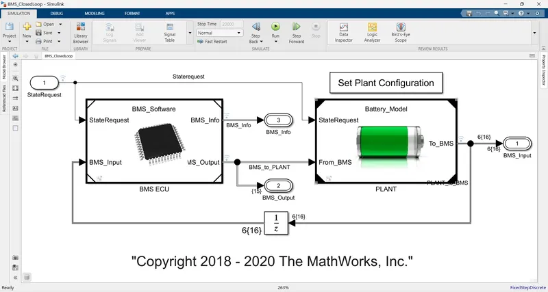
The state machine logic is implemented as:
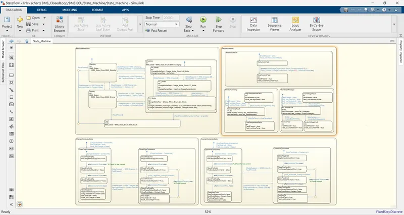
In this, there are 4 parallel states, i.e. they can run concurrently if their default conditions are true. The first state is the main state machine, which has 4 sub states: standby, charging, driving and fault. The default entry state is the standby state. From this state, based on the user inputs the BMS switches between the driving and the charging states. However, the fault state is something that the BMS system senses by itself, based on any malfunctioning detected.
The other parallel state is the fault monitoring state wherein any fault in the pack regarding current, temperature or voltage is monitored and accordingly actions taken. The other two states are corresponding to the inverter and charger contactors. The control logic for inverter circuit is given as:
- First, the negative contactor is closed.
- Then the pre-charge contactor is closed. The pre-charge resistance connected in series with the pre-charge contactor limits high current flowing through the circuit.
- Once the voltage across the load quickly reaches the battery pack voltage, the positive contactor is closed and the pre-charge contactor is opened.
- While disconnecting the load from the battery, first the pre-charge contactor is closed.
- Then the positive and pre-charge contactors are opened sequentially, which is followed by the opening of the negative contactor.
- When the vehicle is not under the driving state or when there is some fault present then the contactors will open up.
The opening and closing of the charger contactor is the same as the inverter one.
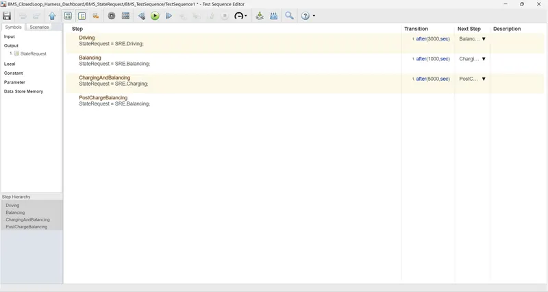
1. Based on these logics, there are three test cases
A. This test case has three operating states of the BMS in it: driving, charging and standby. The test case has been defined as:
The results after simulation are as:
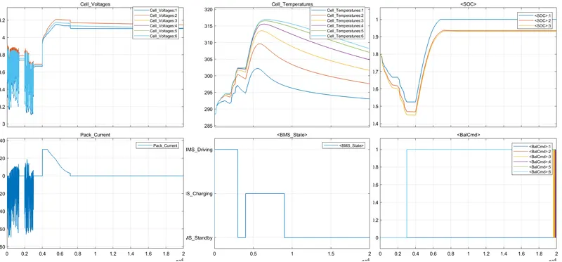
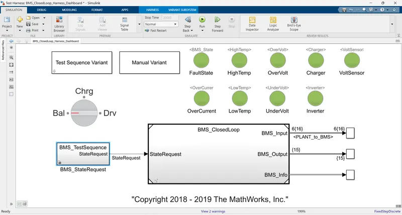
As can be seen, the cycle is at standby by default. During the driving phase, the voltage and current fluctuate as per the load. During the charging phase, the charger implements the constant current charging initially and after that, it switches to the constant voltage charging once the maximum voltage is reached. After charging is complete, the BMS switches to the standby mode.
B. In this test case there are only 2 states, the driving and charging state. As the temperature increases during charging, the BMS enters into the fault mode.
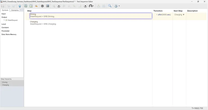
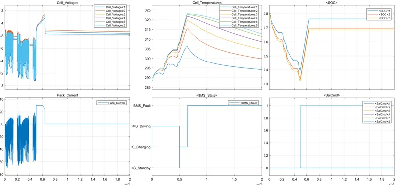
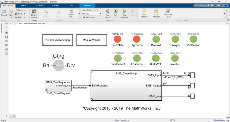
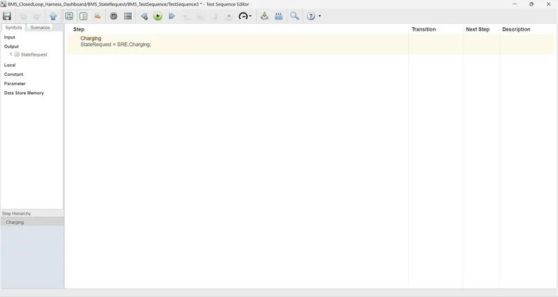
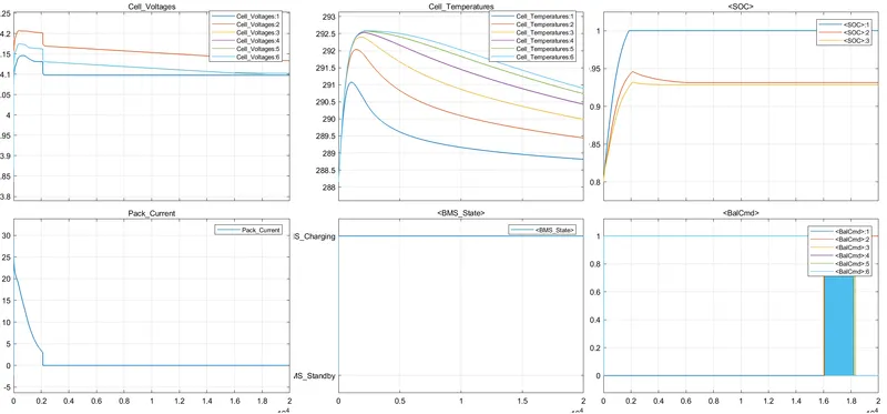
C. This test case has only the charging state. The BMS system charges the load initially. As, there is no transition after the charging state, the BMS system remains connected in the charging state albeit without the transfer of charge.
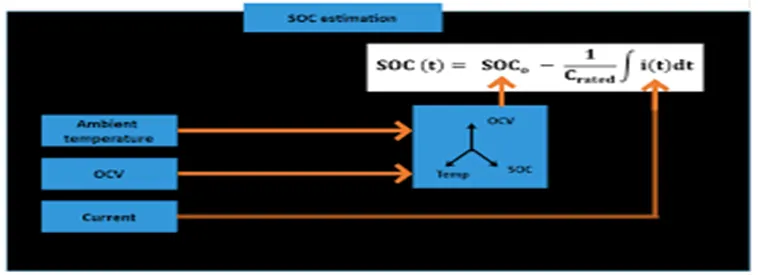
2.The Coulomb counting method measures the discharging current of a battery and integrates the discharging current over time inorder to estimate SoC. Coulomb counting method is done to estimate the SoC values, which is estimated from the discharging current and previously estimated SoC values, SoC is calculated by the following equations:
In the model, this equation is implemented using the discrete time integrator as:
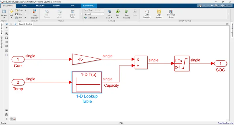
Two inputs come into the system: current and temperature of the pack. Current is converted to capacity (Ah) by dividing with 3600. Then based on the temperature the pack capacity is estimated. This estimated capacity is divided by the discharge capacity and integrated over time which gives the SoC at any given instant.