Week 7 State of charge estimation
Mathlab model is to design the BMS model and to stimulate the plot for different battery characteristics
Model
BMS closedloop
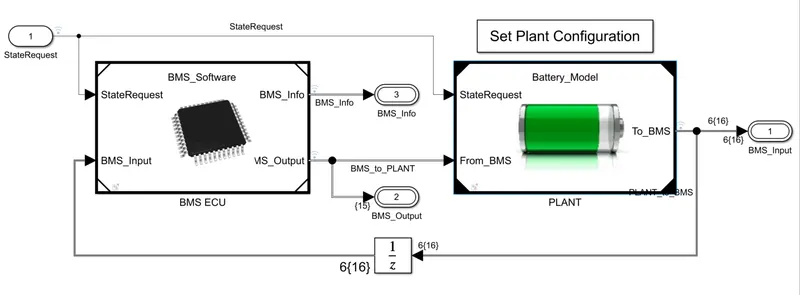
It is a closedloop system which connectes the BMS software and the plant.
BMS software
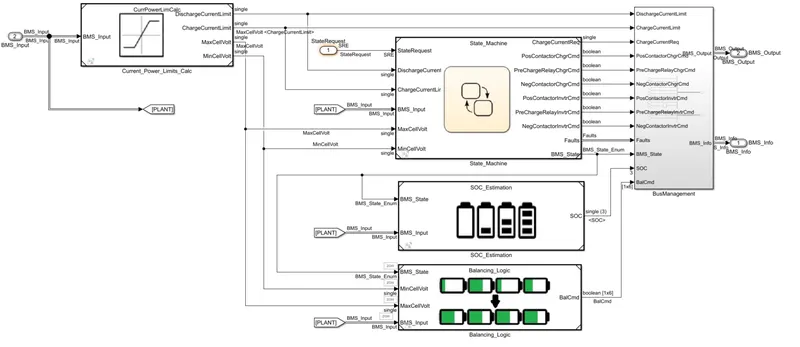
In the BMS software there is a state machine which determines different state based on the other parameters
also ther is SOC estimation Block and balancing logic, this is to estimate soc based on the state and to balance the cell when the battery is not in use.
Battery model
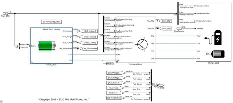
Battery model consist of battery pack, pre charge circuit and charger-load
In the battery pack we have 1 module and 16 module configuration
we have a pre chrage circuit inorder to protect the device and pack during start and cut-off.
BMS harness dashboard
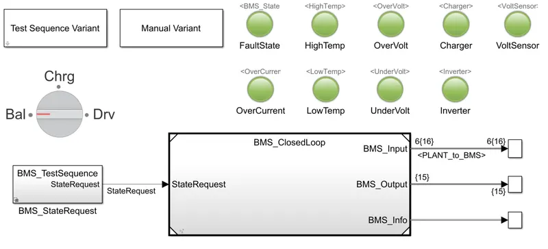
In this we can select between 3 test sequence and based on the test we can see some of the result provided on the dashboard as led.
the test sequence and battery model can be selected based on our need. by selecting it in the subsytem.
the simulation is for 20000 sec
initially we select the test sequence 1
dashboard after test
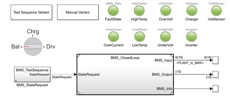
from the dashboard we can see that the there was no fault in the system
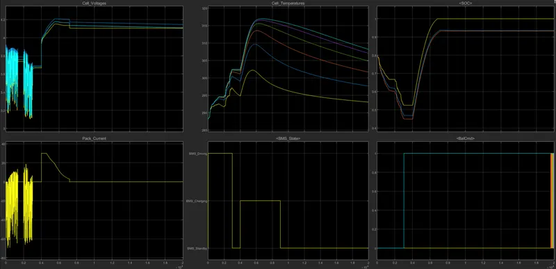
The vehicle is in driving state from starting to around 3000sec after that tiil 4000sec it was in standby state and from 4000 sec to 9000sec the vechicle was in charging state and then was in standby mode till the end of the simulation.
the cell voltage varies during the driving state and during charging the voltage reaced 4.2v ie. max voltage it han handle and during the stand by time the cell ballancing occurs and et the end of the simulation the voltage of all cells was almost constant.
The cell temp increased during the driving condition and we can also see a rapind increase during charging which get reduced during the standby time.
pack current also varies during the driving mode and there was a sudden increase when the chragung started and later get decreased.
SOC decreases during driving and then there was a steep increase during the initial state for charging and then get reduced around reaching 85% soc percentage and durong stand by time SOC remained constant.
cell balancing occurs when the battery was charging and during the standby state.
Test sequence 2
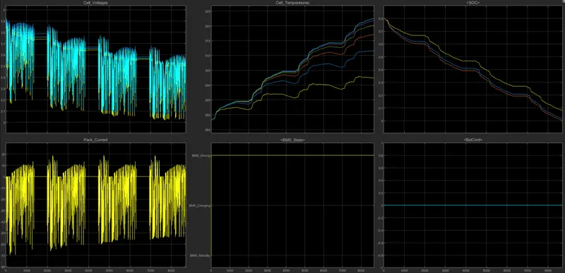
Im the test sequence 2 we can see driving state throughout the simulation.
SOC depletes from 80% to 0 at the end of simulation and we have no cell balancing.
The cell temp rises throught out the simulation.
cell voltage and current varies through out the simulation.
Test sequence 3
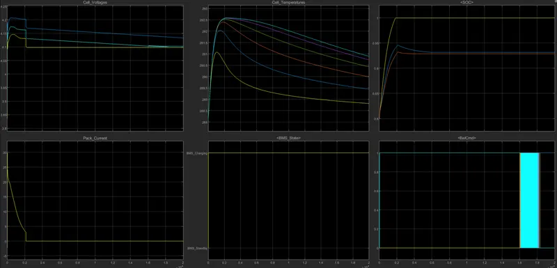
In this test sequence the system is in charging thought out the simulation. The SOC rises from around 80% to 95-100% around 2000 sec and then remains constant thorought out the rest of the simulation.
the sell balancing occures througth out the simulation and the temp of the sell increasec inititally and upon reaching 100% SOC the tenp starts to decrease. Cell voltage reaches to a peak value at the begining of the simulation and then is recuded to 0 around 2000 sec.
the cell voltage reches 4.2 initially and then due to cell balancing the voltage gets reduced due to which the voltage difference between cells is reduced.
from tthe 3 simulation results we can understand that the cell balancing occurs during charging and unused condition f the battery.
cell temp increases during both charging and discharging condition but the rise during charging is more compared to discharging.
during charging the current inseases to a peak value initially and then gets reduced
during driving state the voltage and cell current varies rapidly.
COULOMB COUNTING METHOD
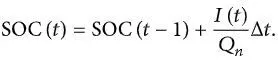
The Coulomb counting method measures the discharging current of a battery and integrates the discharging current over time in order to estimate SOC. Coulomb counting method is done to estimate the SOC(t), which is estimated from the discharging current, I(t), and previously estimated SOC values, SOC(t-1).
SOC is calculated by the following equation:
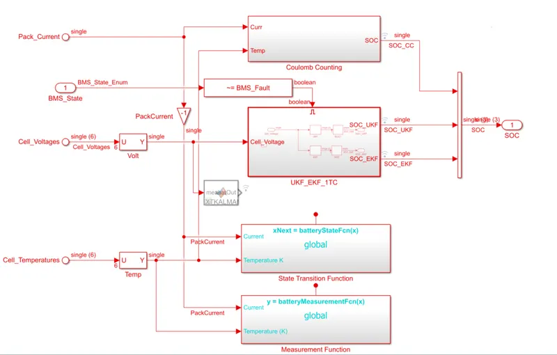
In the bMS model the coulomb counting is present in BMS software inside it SOC estimation part is present which has BMS state as input and SOC as output.
In the SOC estimation block coulmb counting block is present along with other block namely measurement fuction state transition function.
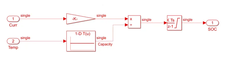
Here coulomb counting is implements using the equations provided above
In our system we take pack current and temp as input. The curent is passed through a gain and the temp is passed through a lookup table and the both output are divided and then passed to time integrator and as a output we get SOC. In the lookup table we have relation between temp and capacity.