Project 1
Therory
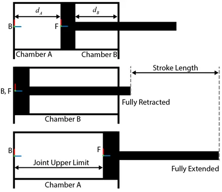
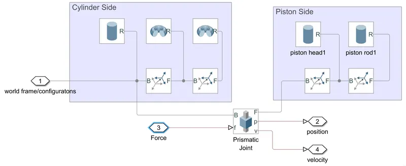
You can model the mechanical part of the system in Simscape Multibody. For example, to model the cylinder and piston, you can use the Revolved Solid (Simscape Multibody) and Cylindrical Solid (Simscape Multibody) blocks. To provide the translational degree of freedom for the piston, use a Prismatic Joint (Simscape Multibody) block. To easily calculate the lengths of the chambers A and B, you can attach the base frame (B) and follower frame (F) of the joint to the centers of the left inner surface of the chamber A and the left surface of the piston, respectively. Make sure that the Z-axes of the B and F frames are aligned and both point toward chamber B.
Using this convention, the length of the chamber A, dA, is the position output of the joint block, and the length of the chamber B, dB, equals the difference of the stroke length and dA. To ensure that the piston does not travel beyond the ends of the cylinder, you can specify the upper and lower position limits of the Prismatic Joint block.
In chamber A, a pressure at port A moves the piston from 0 to stroke length. The displacement of the piston equals to the position output of the Prismatic Joint block. To model chamber A:
-
Connect the ports C and R of the Translational Multibody Interface block to the ports C and R of the upper Translational Mechanical Converter (IL) block, respectively.
-
In the Translational Mechanical Converter (IL) block, set Interface displacement to
Provide input signal from Multibody jointto enable port p. -
Connect ports p of the Prismatic Joint block and Translational Mechanical Converter (IL) block.
In chamber B, the pressure at port A moves the piston from 0 to negative stroke length. Therefore, you need to change the default orientation and add an offset to the input position signal of the lower Translational Mechanical Converter (IL) block. The offset equals -dB.
-
In the lower Translational Mechanical Converter (IL) block, set Mechanical orientation to
Pressure at A causes negative displacement of R relative to C. -
Set Interface displacement to
Provide input signal from Multibody jointto enable the port p. -
Add a PS Constant block and specify the constant as the stroke length of the cylinder.
-
Add a PS Subtract block, then connect it to the PS Constant and Prismatic Joint blocks as shown in the diagram. Note that the output of the PS Subtract block equals -dB.
To limit the travel of the piston:
-
In the Prismatic Joint block, under the Limits section, select the Specify Lower Limit and Specify Upper Limit parameters.
-
Under the Specify Lower Limit section, the Bound parameter indicates the minimum distance between the frames B and F of the joint block. In this example, specify the Bound parameter as 0 m.
-
Under Specify Upper Limit, the Bound parameter indicates the maximum distance between frames B and F of the Prismatic Joint block. In this example, specify the Bound parameter as the stroke length of the cylinder.
Double-acting cylinder systems can be used in many applications. For example, a dump trailer can use a double-acting cylinder to actuate a scissor hoist mechanism that raises and lowers the dump bed. See Hydraulic Interface - Dump Trailer with Hydraulic Cylinder (Simscape Multibody) for more details. Under the mask of the Double-Acting Hydraulic Cylinder block in the scissor hoist are the mechanical and hydraulic subsystems, which are connected by a Translational Multibody Interface block. The Prismatic Joint block in the mechanical subsystem provides the position information to the two actuators in the hydraulic subsystem, Head Chamber and Bottom Chamber, that have the opposite settings of the Mechanical orientation parameter. The Constant block C provides a position signal offset to the Head Chamber actuator, because when the Bottom Chamber is at dead volume (where position p = 0), the Head Chamber is at maximum stroke.
MODEL
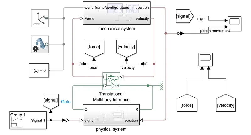
mechanical system
physical system
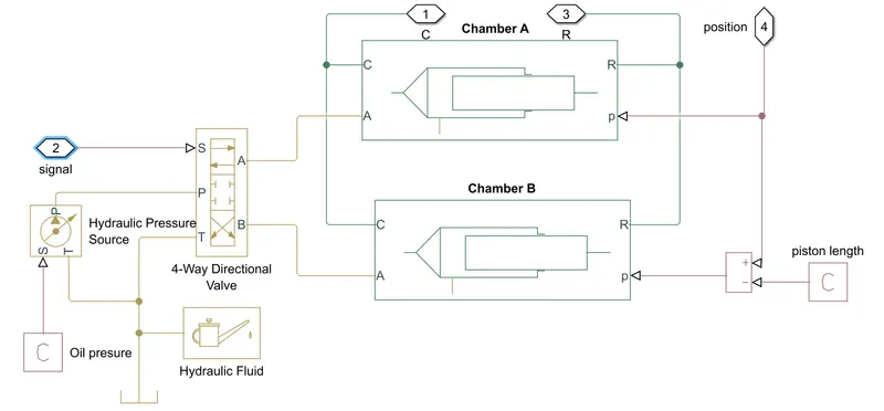
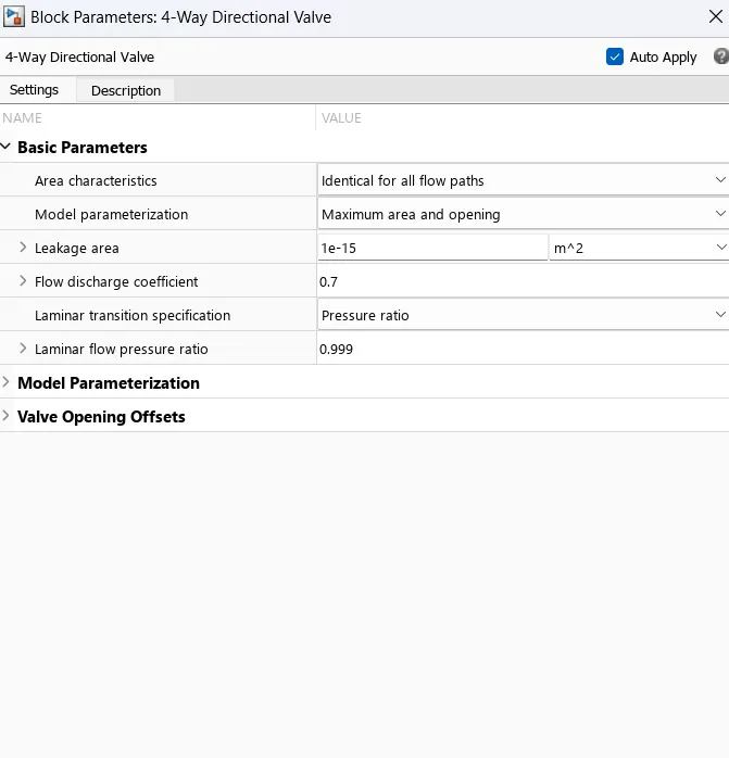
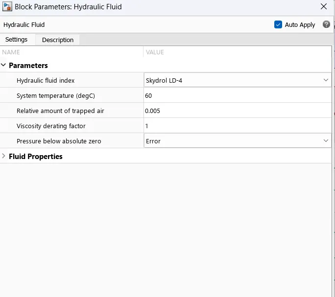
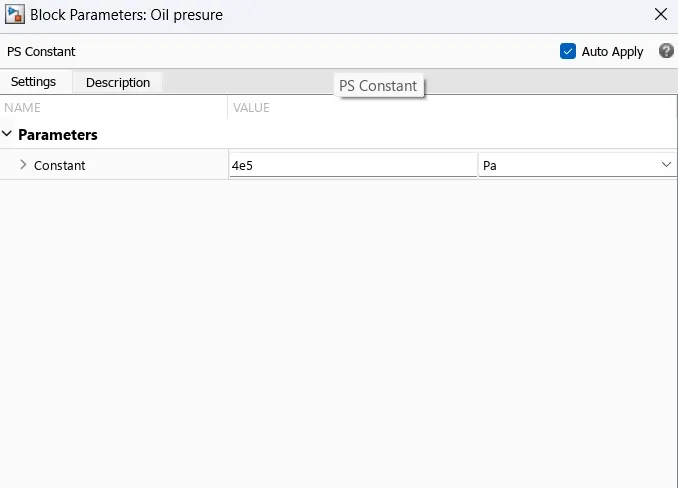
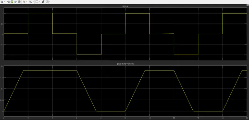
The hydraulic oil is suppied by the source. The hydraulic oil is passed to a 4 way valve which changes the position according to the input given. Here we are using a signal builder to provide input. The A side of the valve is connected to the chamber A and the B side is connected to the chamber B. The A and B chambers acts in opposite direction. The output of the camber is provided to the translational multibody interface which produces a force based on the movement.
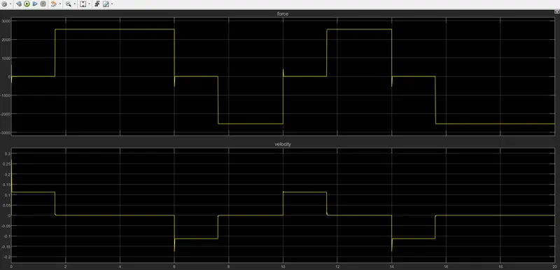
The force is then transferd to prismatic joint as input. The prismatic joint moves accourding to the input provided and a actuation is created on the multibody side. The multibody consist of a cylindical solid for piston side and a cylindrical and two revolute solid for cylinder side.
A solver configuration , mechanism configuration and world frame is attached to the model.
Multibody
cylinder head
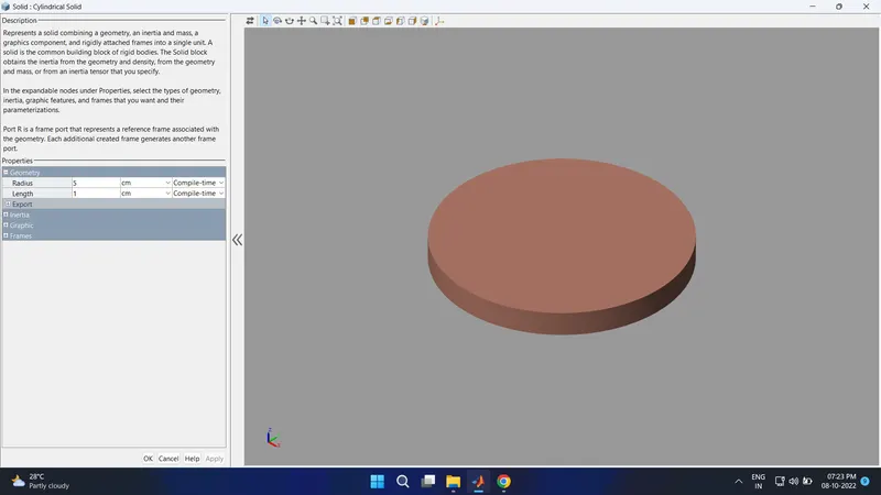
body
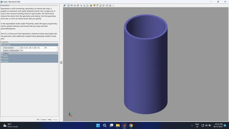
bottom
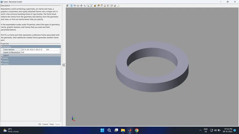
piston head
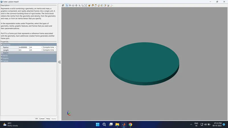
piston rod
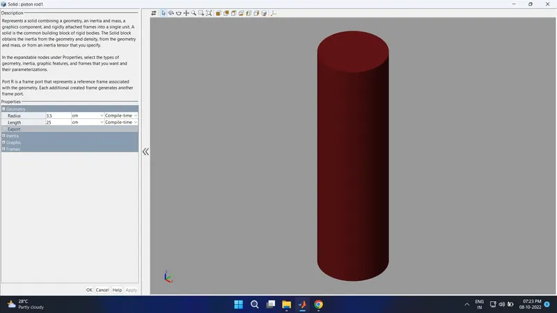
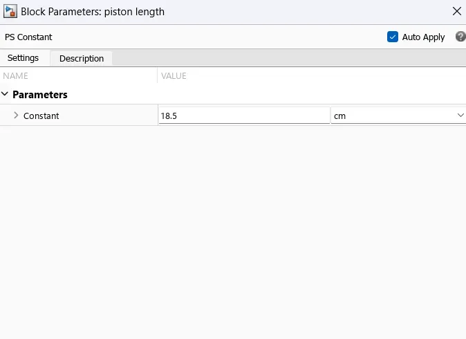
parameters
Results
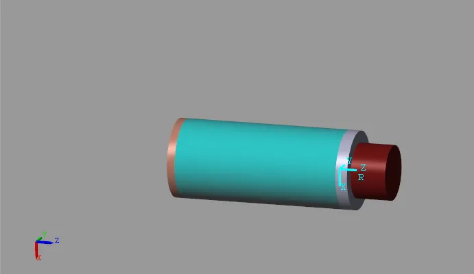
multibody at 1 sec of simulation time
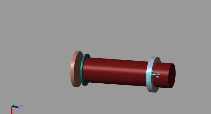
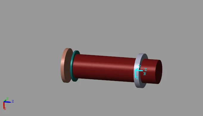
multibody at 4 sec of simulation time
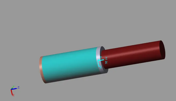
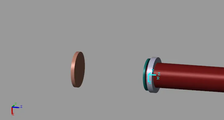
multibody at 8 sec of simulation time
signal input vs multibody movement plot
force and velocity plot (prismatic joint)
referance
https://in.mathworks.com/help/simscape/ug/modeling-a-double-acting-actuator.html