Week 7 State of charge estimation
1.Simulate the 3 test cases from harness dashboard and write a detailed report on the results ?
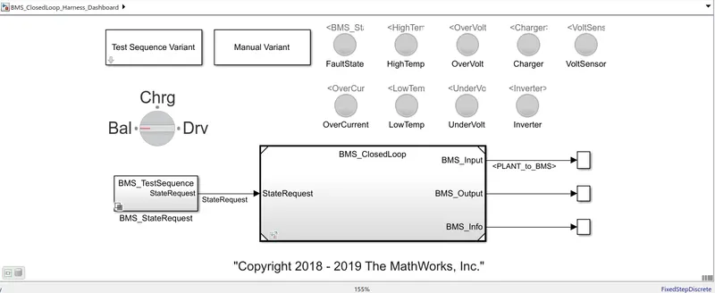
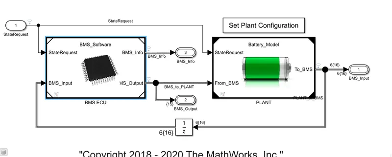
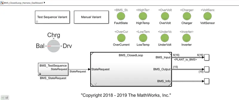
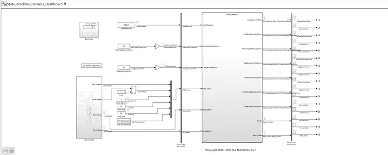
Harness Dashboard : This is a simulated environment where we create 3 test cases and load the battery pack according to the drive cycle given by test cases. We create test specific environment for testing specific model. We perform closed loop testing by creating physical plant model and we test the potential of the model. We can use test harnesses which offer management and synchronization capabilities.
Initially when no test is conducted we can see below harness board.
TEST CASE 1 :
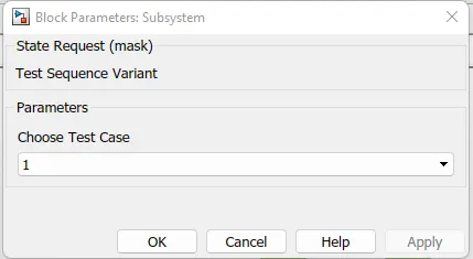
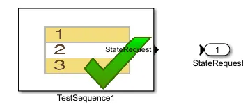
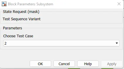
We select 1 in state request and can see below, test sequence 1 is selected.
In test case 1, first comes driving condition for 3000 sec where battery pack is discharged accordingly. After 3000 sec balancing condition comes where battery pack and cells undergo balancing according to balancing logic. After 1000 sec from then comes the Charging & Balancing step where Charging along with cell balancing occurs. Finally after 5000 sec of above operation Post Charge Balancing Starts. Thus test sequence 1 stops. All steps are mentioned below.
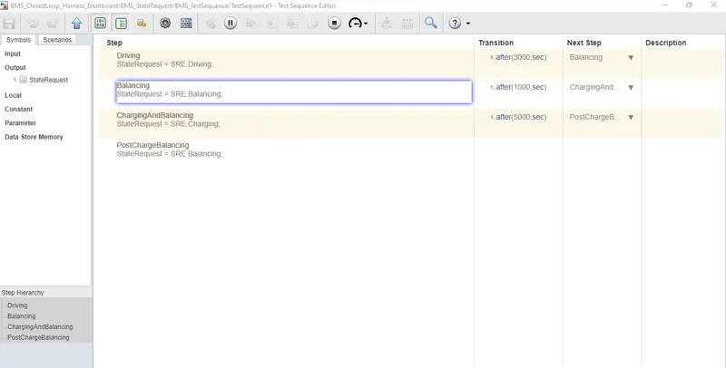
As all sequence steps are executed well no error occurs and all are in green which is healthy condition.
RESULT :
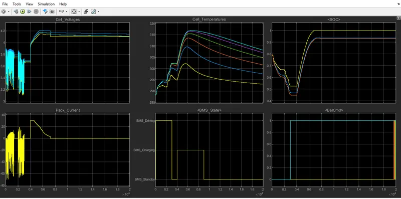
Explanation :
- Initially as pack discharges as per driving cycle we see voltage and current variations, temperature rise in all cells, reduction in SOC upto 45% (as per kalman filter SOC estimation) & 55 % (as per Coulomb Counting estimation),
- BMS state is in driving mode in graph upto 0.3 (i.e., 3000 sec) and slowly after that cell balancing happens for 0.1 or 1000 sec where voltage stabilizes to 3.7V nearly,
- BMS in standby state,
- Balancing increases to 1 & remains the same as per graph.
- Now after 4000 sec Charging along with balancing starts (for 5000 sec from now)where initially CC(constant current) charging happens for 1000 secs upto 5000 sec where cell voltage rises, reaches upto 4V
- And from there on wards CV(constant voltage) charging mode is enabled where pack current gradually falls & voltage rises, reaches 4.2V.
- Now SOC rises to 90-95% by end of 6000 sec and max SOC is maintained from 7000 sec on wards,
- BMS Charging mode is upto 9000 sec.
- Cell temperatures gradually fall from 6000 sec on wards.
- After 9000 sec post charging & balancing happens thus all parameters reach their stable state.
- Now BMS goes to standbymode.
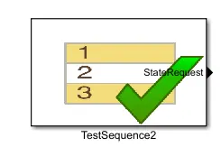
TEST CASE 2 :
RESULT :
Explanation :
Here in this case ,
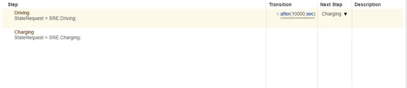
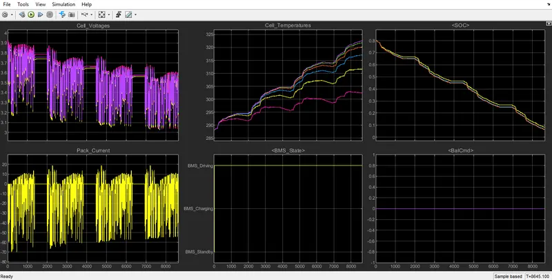
- We perform driving for 10000 sec initially and after that we go to next step as charging. Simulation stops after 8500 sec, simulation error occured.
- But as the time is not mentioned aftert this step dash board returns faultstate & high temperature indicating alarm as battery is completely discharged.
- SOC falls to near zero.
- BMS state is in driving mode.
- Cell balancing doesn't happen.
- Cell voltage reduces to nearly 3V and reaches 3.5V after driving cycle completes .
- Temperature rises over 325 degrees etc..,
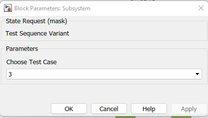
TEST CASE 3 :
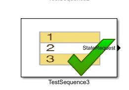
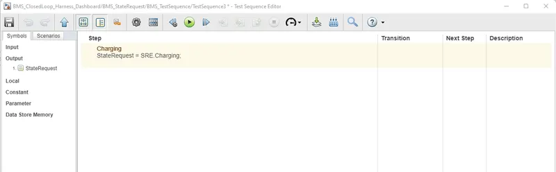
RESULT :
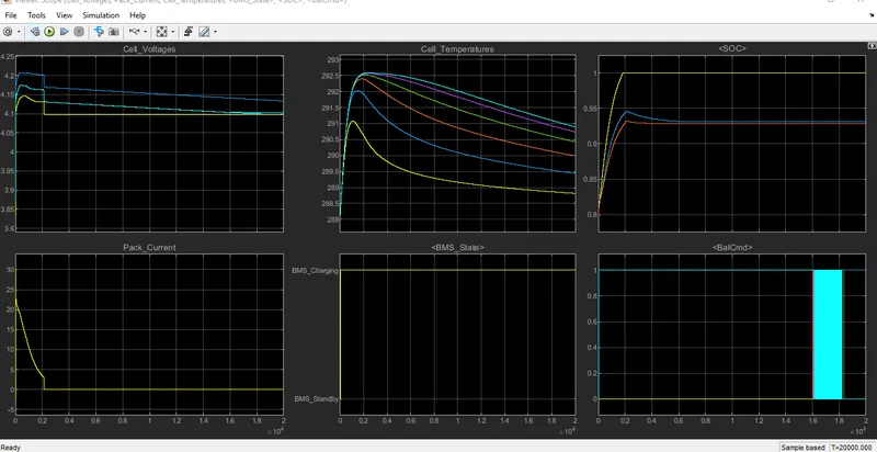
Explanation :
- In this test sequence we perform charging of the pack where,
- Different Cell voltages are reached in 2000 sec as per graph where current falls drastically and CV charging occurs to charge cells and reaches 4.1 -4.2 V almost.
- Temperature rises during charging and falls gradually after 2000 sec .
- SOC also rises immediately to 95 - 100 % nearly.
- Cell balancing occurs from the start only as seen in graph.
- BMS in charging state as shown above in graph.
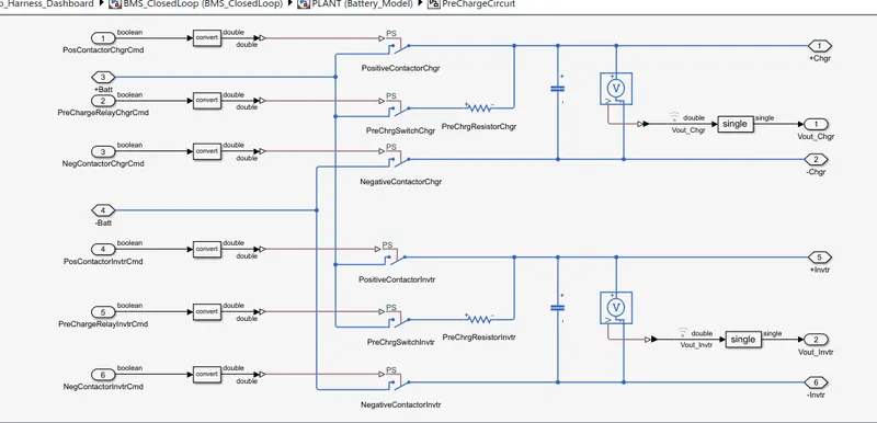
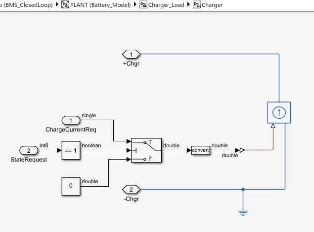
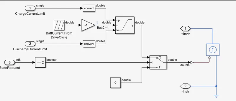
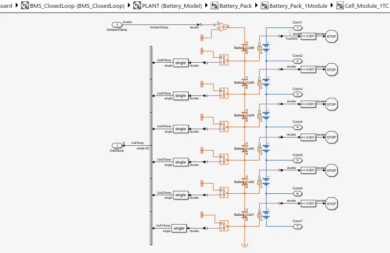
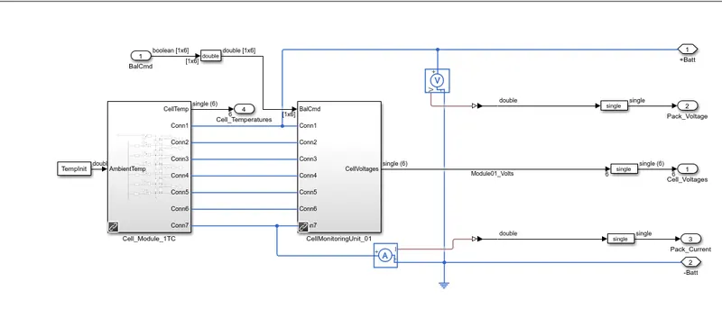
Fewer circuits below :
PLANT
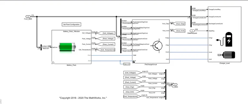
PRECHARGE CIRCUIT
CHARGER & LOAD
6 CELLS MODULE
STATE MACHINE
2.What is coulomb counting? Refer to the above model and explain how BMS implements coulomb counting for SOC estimation ?
INTRODUCTION :
The state of charge (SOC) of a battery is a measure of the available energy or remaining charge in that battery. It is defined as the ratio of the amount of charge that can be extracted at a specific point in time of a battery to the full capacity of that battery. A battery that is fully charged is said to have a state of charge of 100% , whereas a battery that is fully discharged is said to have a state of charge of 0%. The state of charge can be expressed mathematically by the formula below:
SOC(t)= Q(t)/Q(n)
where Q(t) = Charge @ given time , Q(n) = Charge @ full capacity.
INTRODUCTION :
A battery management system (BMS) is an electronic embedded system that combines hardware and software to manage a rechargeable battery systems. The BMS performs a variety of functions to ensure that a battery operates always within its safe operating limits and has the longest possible working life. Without a BMS, a user will not have any control over the way a battery gets charged or discharged because the battery itself is not aware. For instance, a battery does not know it's own SOC,operating limits,when to disconnect or connect to demanded load etc..,
BMS ECU :
In the application of EVs and HEVs, BMS have the following functions:
- Measurement
- Energy management
- Thermal management
- Computation of Cell & pack parameters
- Communication
- Protection
- Optimization
Measurement
This feature involves the BMS continuously measures & monitors various parameters of the battery & sense the overall state of the battery. The different parameters that a BMS checks over are :
1. Voltage - this is measured for the individual cells as well as for the overall battery pack.
2. Current - this is measured for overall battery pack to check for overcurrent discharge limit.
3.Temperature - this is measured for the individual cells as well as for the overall battery pack.
4. State of Charge (SOC)
5. State of Health (SOH) : It is defined as the ratio of the maximum battery charge to its rated capacity. Ageing is a factor which is concerned. It is expressed as a percentage as seen below.
Qmax/mAh= The maximum charge available of the battery
Cr=The rated capacity
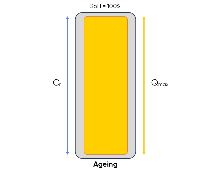
Figure : Evolution of battery during aging
Energy Management
The electric vehicles which are capable of regenerative braking, the BMS will manage & control current flow from motor / generator to battery pack. Also Cell balancing is the major part in the energy management. BMS ECU follows certain algorithms depending upon computational parameters data of individual cells like V,I,T.
Thermal Management
The BMS is responsible for monitoring the temperature of the battery pack and to make sure that the temperatures remain within the safe operating ranges of the cells (as per limits mentioned in their data sheet). It is important to monitor and control the temperature because charging & discharging currents, ambient temperature around can influence the temperature to exceed their limits. The thermal management may be active or passive and the cooling medium may be liquid, air or some substance that undergoes a phase change when comes in contact with heat.
Passive cooling relies on the convection of the surrounding air. But this type of cooling is not an efficient approach. So Liquid cooling is preferred by some automakers because liquids like water have higher thermal conductivities than air which can give efficient cooling than air and therefore have higher natural cooling potential. In Tesla cars is an ethylene glycol-based G48 coolant is used as it's great for preventing corrosion, freezing, and overheating in the Tesla battery pack. The batteries may be submerged in the coolant or the coolant may flow in the Battery pack along module walls with specialized pipe construction adjacent to battery pack modules, without coming in contact with the batteries. In Tesla cars mostly Liquid Cooling is used to cool the packs as their capacity is larger.
Computation
This feature of a BMS involves being able to perform number of calculations based on input parameters from different sensors and current conditions of the battery. For instance, the BMS performs calculations to tell us the SOC of the battery pack which indicates the available range that can be achievable with the amount of charge available in the battery pack. The BMS can even tell us the age, SOH of the battery pack by counting the number of cycles it has been charged/discharged upto till date.
Communication
This feature is about the BMS being able to communicate with other systems(Ex: Battery pack, Inverter, Motor, Sensors etc..,) in order to work together efficiently. For instance, the main controller of the BMS can communicate with its own hardware at the cell level and can even communicate externally to dashboard.
Protection
The BMS is mainly responsible for the protection of the battery pack.It ensures that the battery is always operating within its safe limits without causing any harm to equipment hardware & to the end user. For instance:
- Over current discharge - This is when the battery is being discharged at a higher C rate than recommended which is not advisable.
- Over current charge - This is when the battery is being charged at a C rate higher than recommended which is dangerous & cause potential damage to cells.
- Discharging below cutoff voltage - This is when the battery is discharged to a level below the cutoff voltage which is not advisable & battery could go dead.
- Charging above full charge voltage - This is when the battery is charged to a voltage level above the full charge voltage.
- Temperature - The battery should not be at a temperature outside its safe operating range at any given instant time. This includes over temperature (causes thermal runaway)and under temperature(causes inefficient operation of cell & pack).
Optimization
This is afeature of a BMS which involves in making sure that the battery is used as efficiently as possible by ensuring that the maximum capacity of a battery is utilized and the cell balancing occurs. Cell balancing is needed when individual cells are not at the same voltage level, or are not at the same SOC, or are not charging / discharging with the same current. Cell balancing is done by two main ways:
Active : Active balancing involves shuffling energy from the highest charged cells to the lower/lowest charged ones which makes sure that no charge is wasted.
Passive : Passive balancing is where the extra energy in the more charged cells is dissipated as heat energy by connecting them to some load resistor.
INTRODUCTION :
The state of charge (SOC) of a battery is a measure of the available energy or remaining charge in that battery. It is defined as the ratio of the amount of charge that can be extracted at a specific point in time of a battery to the full capacity of that battery. A battery that is fully charged is said to have a state of charge of 100% , whereas a battery that is fully discharged is said to have a state of charge of 0%. The state of charge can be expressed mathematically by the formula below:
SOC(t)= Q(t)/Q(n)
where Q(t) = Charge @ given time , Q(n) = Charge @ full capacity.
An alternative parameter to express the amount of charge i.e., available in a cell is referred to as the 'Depth of Discharge' or DoD. It tells us how much a battery has been discharged from its full capacity.It basically indicates the emptiness in cell which is depth of discharge and so a DoD of 1 means a fully discharged condition and 0 means a fully charged condition.
NOTE :
It is important to note that the SOC of a battery will change over time as the battery is used and charged. For example, a brand new battery will have a SOC of 100%, but as the battery is used, the SOC will decrease. Similarly, a battery that has been partially discharged will have a SOC of less than 100%, but as the battery is charged, the SOC will increase.
The different methods for SOC estimation are :
Voltage Method
This method measures the present voltage of a battery to find its SOC using the discharge characteristics of the voltage vs the SOC. This method is not preferred because the voltage in is more affected by the current in the battery and the battery temperature. This method does not take in to account the temperature variations that can cause the terminal voltage of a cell to vary from its open circuit voltage (OCV). Considering an LFP cell, its discharge characteristics are rather flat showing a linear relation between the OCV and the SOC and this decreases the accuracy of the SOC measurement further.
Current Integration Method
This method is also known as the 'coulomb counting' method and involves measuring the current entering the battery (charging) and leaving the battery (discharging) over the time. Since charge is measured in Coulombs and this method measures the amount of charge entering or leaving a cell, this method is referred to as Coulomb counting as well. A device called a coulomb counter will measure the current consumed or supplied to the cell, finds the total current flowing in or out of the cell over a period of time and compares it with the available battery capacity to find the SOC.
- Even though this method is the most accurate way of measuring the SOC, it is not perfect. For instance, the method suffers from a long term drift and a lack of a reference point as the measuring capability is limited by the sensor accuracy.
- This means that the SOC has to be re-calibrated again back to 100% every time when a battery is charged fully.
- This method also does not consider the efficiency of the battery which is necessary SOC measurement.
- Battery temperatures are always subject to change depending on their charging / discharging currents and this will affect their performance efficiencies accordingly.
- The cycle life of a battery also affects the coulomb counting method because working life of a cell, its efficiency and its usable capacity would have decreased over time after no. of operations.
- This can in turn affects the SOC measurement.
The current integration method can be expressed mathematically as shown below:
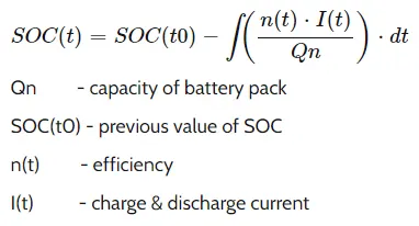
Starting time of charging/discharging -t0
End time of charging/discharging -t
Nominal capacity of cell -Qn
Efficiency of cell presently - n(t)
Current flowing at end time -I(t)
Time interval -dt
This above integral can be further simplified when expressed like so:
SOC(t)=SOC(t0)+[I(t)/Qn]* `Delta`t
From the equation above, we can see that the SOC estimation requires the main information of the previous estimated SOC value and the charging / discharging current and the time interval for which the charge / discharge takes place.
Coulomb Counting :
The Coulomb counting method measures the discharging current of a battery and integrates the discharging current over time in order to estimate SOC . Coulomb counting method is done to estimate the SOC(t) , which is estimated from the discharging current,I(t) , and previously estimated SOC values SOC(t-1). SOC is calculated by the following equation:
SOC(t)=SOC(t-1)+[I(t)/Qn]* `Delta`t
But there are several factors that affect the accuracy of Coulomb counting method including temperature, battery history, discharge current, and cycle life .
Modified Coulomb Counting Method :
To improve the Coulomb counting method, a new technique called modified Coulomb counting method is proposed. The modified Coulomb counting method uses the corrected current to improve the accuracy of estimation.
The corrected current is the function of discharging current. There is a quadratic relationship between the corrected current and discharging current of battery. By practice of experimental data, corrected current is calculated by the following form:
`I_c(t)`=`K_2``I(t)^2`+`K_1``I(t)`+`K_0`
Ic(t)= Corrected Current
I = Discharge Current
where K2,K1,K0 and are constant values obtained from the practice experimental data.
In modified Coulomb counting method, SOC is calculated by the following equation:
SOC(t)=SOC(t-1)+{[Ic(t)/Qn]* `Delta`t}
The experimental results show that the accuracy of the modified Coulomb counting method is superior to the Conventional Coulomb counting method.
Kalman Filtering Method
This method is used to overcome the disadvantages and problems with measuring the SOC using the voltage method and current integration method. This method implements a Kalman filter which will use the electrical model of a battery to predict its over voltage due to the current. It can be used together along with the current integration method to accurately measure the SOC. The main advantage of a Kalman filter is that it is able to adjust its trust of the battery voltage and coulomb counting in real time.
BMS ECU SOFTWARE ARCHITECTURE :
Below we find current power limiter,State machine,Bus Management,SOC Estimation,Balancing Logic.
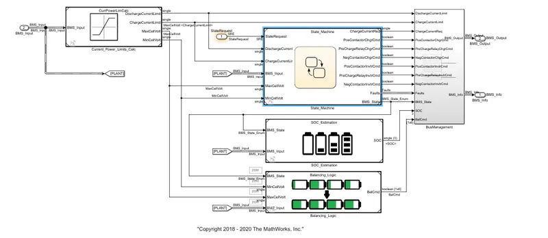
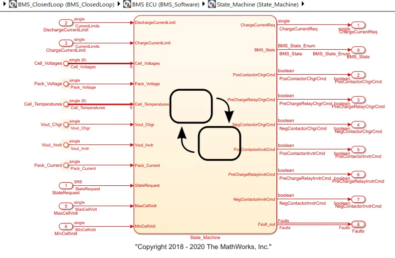
State Machine results in Operational state of the vehicle like charging or driving or standby mode etc..,
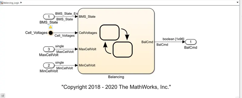
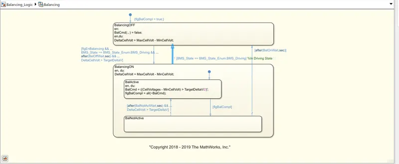
Above we find Balancing logic followed by the system which balances the cells and pack according to the usage of the pack. Cell balancing is necessary for optimal utilization of pack.
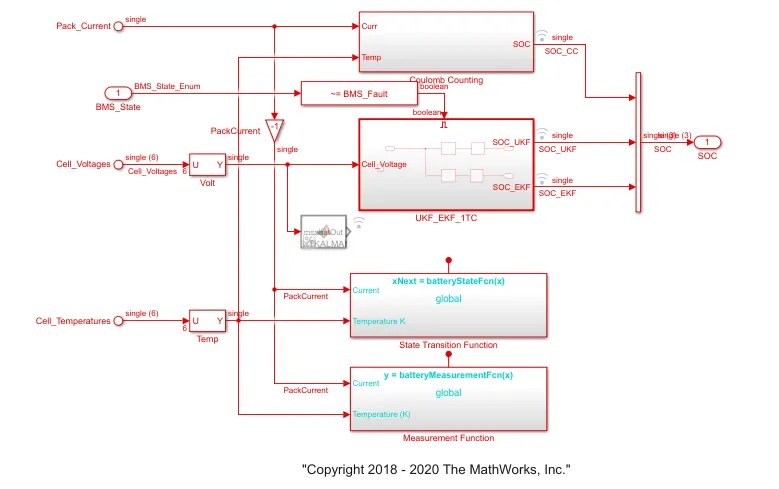
In the above model BMS ECU Implements the SOC Estimation different ways Coulomb Counting , Unscented Kalman Filter UKF , Extended Kalman Filter EKF to accurately estimate SOC. It is called Hybrid Method.
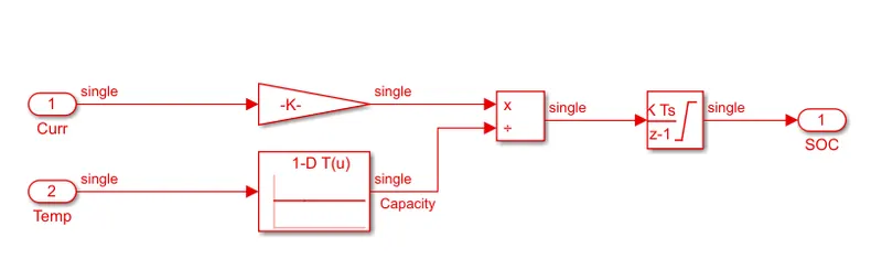
Coulomb Counting estimation above takes input 1 as current and given to gain block & input 2 as temperature given to capacity as temperature raises according to it. Both are given to discrete time integrator which works in Z transform and integrates signal over running time and thus estimates SOC.
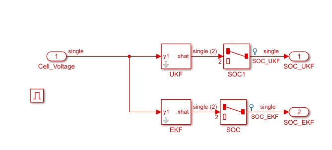
Kalman Filter above uses matlab defined UKF & EKF which perform estimation of non linear plant model which are given to SOC selector switches and given as final SOC estimate output respectively.
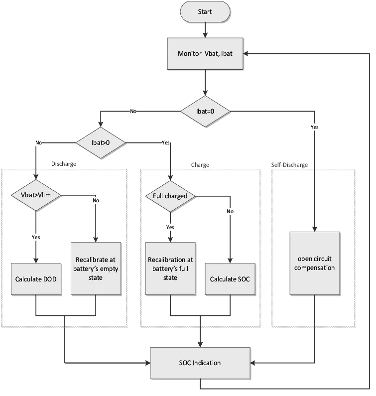
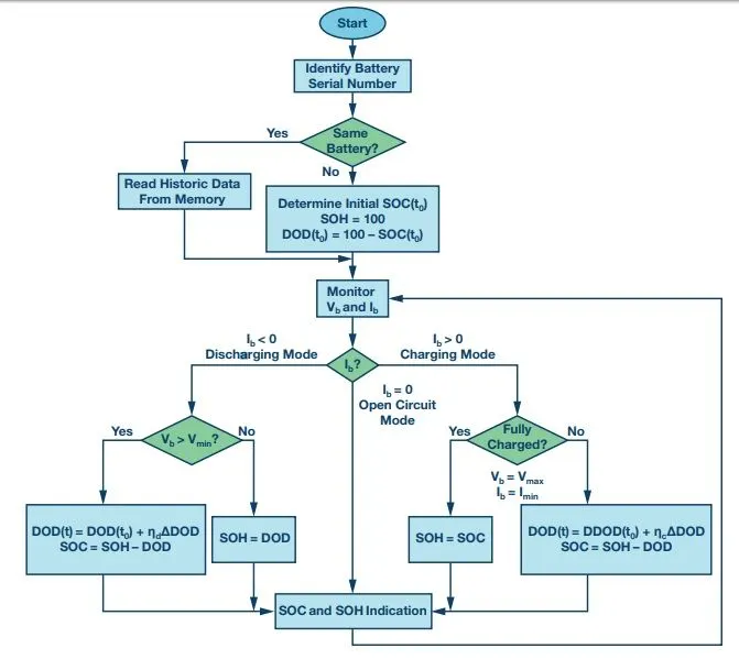
General Coulomb Counting algorithm :
Below we can see how SOC estimation is done .Firstly we monitor V,I of cell and go to estimate limits and current values of them and following sequence is implemented for determining SOC during charging and DoD during discharging.
KALMAN FILTER ALGORITHM :
Principle Circuit : The Kalman filter is an optimal observer whose principle is illustrated in Figure. The principle is to minimize, in real time, the errors between the estimated and the measured outputs, using a feedback that adjusts the uncertain variables of the used model. By such a model, it is possible to observe the physical parameters of the model that are not accessible to measurements. The correction is weighted by a gain vector K that allows correction of the dynamic and the performance of the filter. The gain is calculated at each iteration from error predictions and uncertainties (noise) on states and measurements. The filter dynamic control is then based on the initialization of the noise matrices of states Q and measurements R, as well as through the initialization of the matrix of error covariance P.
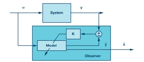
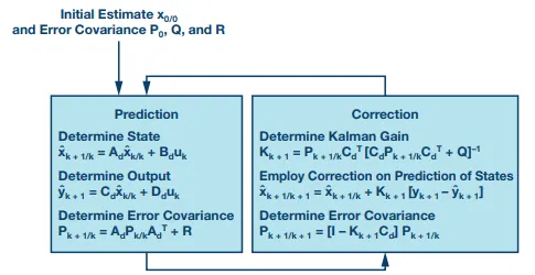
The Kalman filter algorithm, illustrated takes place in two phases:
- The first concerns the initialization of the matrices P, Q, and R, and
- The second concerns the observation which is composed of two steps at each sampling interval.
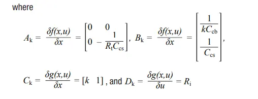
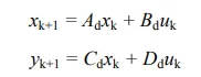
First, the algorithm predicts the value of the present state, output, and error covariance. Second, by using a measurement of the physical system output, it corrects the state estimate and error covariance. So, the extended Kalman filter is applied to obtain SOC estimation for a lithium battery pack.Experimental results show that the proposed extended Kalman filter-based SOC estimation method is effective and can estimate battery SOC accurately.
Enhanced Coulomb Counting Algorithm
In order to overcome the shortcomings of the coulomb counting method and to improve its estimation accuracy, an enhanced coulomb counting algorithm has been proposed for estimating the SOC and SOH parameters of Li-ion batteries. The initial SOC is obtained from the loaded voltages (charging and discharging) or the open circuit voltages. The losses are compensated by considering the charging and discharging efficiencies.With dynamic recalibration on the maximum releasable capacity of an operating battery, the SOH of the battery is evaluated at the same time.This in turn leads to a more precise SOC estimation.
Conclusion :
Here we tested 3 test cases successfully, estimated SOC of pack using Hybrid Method of prediction.