Project 1 Mechanical design of battery pack
Battery pack capacity: 18 kWh
Cell: ANR26650M1-B
Prepare a detailed battery pack drawing along with its enclosure. State your assumptions.
To prepare a battery pack of any capacity we have to define Voltage,Current which we need to operate the driving system(eg: motor) so that we can draw necessary current from the designed battery pack. We must also design extra capacity of the pack as we are interested to operate battery pack in safe operation without draining 100% of capacity of the pack which improves battery life.
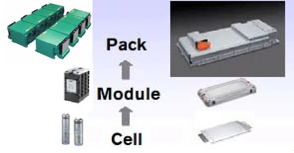
A battery consists of one or more electrochemical cells which convert chemical energy into electrical energy while discharging and electrical energy into chemical energy while charging. We have to connect Individual battery cells are grouped together into a single mechanical and electrical unit called a Battery Module. These modules are electrically connected to form a Battery pack.There are several types of batteries (chemistry) used in hybrid and electric vehicle propulsion systems but we are going to consider only Lithium-ion cells. The main reason is that Li-ion batteries have higher specific energy [Wh/kg] and specific power [W/kg] compared with other types.
CELL Parameters (ANR26650M1-B )
Here, we choose the ANR26650M1-B battery model for our battery design.Lithium Werks’ 26650 cells are best for Power,Safety,Lifeapplications. They deliver very high power due to their use of patented Nanophosphate battery technology. Based on lithium iron phosphate chemistry (LiFePO4), the cells are inherently safe over a wide range of temperatures and conditions. Whether the application requires outstanding cycle life or stable float reliability, the Lithium Werks’ 26650 cells are suitable for a wide variety of power, pulse, or stand-by applications.
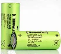
Let us see the cell specification :
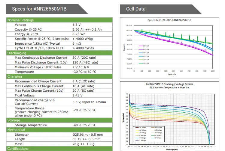
Nominal capacity: 2.56 Ah
Nominal voltage: 3.3V
Charge end voltage: 3.6V
Standard charge current: 3A (1.2C)
Max continuous charge current: 10A (4C)
Max continuous discharge current: 50A (10C)
Max pulse discharge current (10 sec): 120A (24C)
Discharge cut-off voltage: 2.0V
AC impedance at 1KHz: 6mΩ
Weight: 76g
Life Cycles @ 1C rate: > 4000 Cycles
Battery Cell Calculations : Let us calculate cell level parameters required for design.
1. VOLUME OF CELL : Volume of Cylindrical Cell is
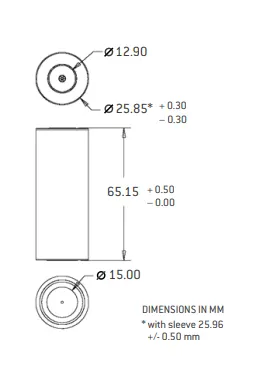
Formula = `pir^2h` = 3.14 * 13*13*65 = 34524 `mm^2`or 0.034524 `m^2`
Volume of the cell = 0.034524 `m^2`
where
r= radius of cylinder = 26/2 = 13 mm
h= height of cylinder = 65 mm
Capacity of each Cell : It is the Energy available in each cell
Capacity of Cell = 3.3V * 2.56 Ah = 8.45Wh energy available per cell.
Energy Density : It is the Energy Available in Cell per unit Volume or unit Weight.
- Volumetric ED = 8.45Wh/0.034524 = 244.7 Wh/L `rarr` Energy per Unit Volume.
- Gravimetric ED = 8.45Wh/0.076 = 111.2 Wh/Kg `rarr` Energy per Unit Weght.
Battery Pack Calculations :
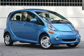
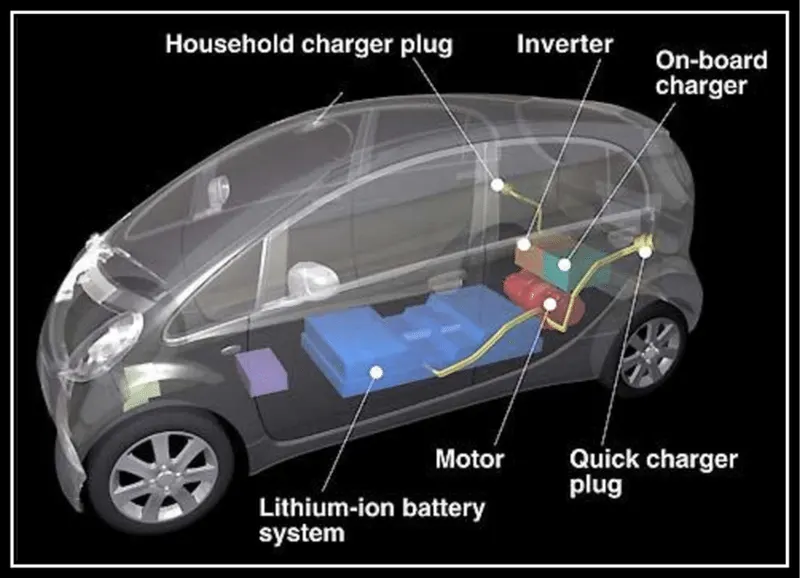
I have taken 330V as reference voltage for the battery pack from an old reference electric car Mitsubishi MiEV(Curb Weight : 1805Kg = 2392 lbs) . As per manufacturer 16Kwh(85km range) is used in this vehicle but here I am interested to update battery pack to 18KWh(105 Km range) & see difference.
We need to know Ah capacity of pack to design Current ,
Necessary Ah = 18000Wh/330V = 54.54 Ah ~ 55Ah.
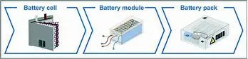
I need 55 Ah battery capacity in the system. So my battery pack rating is 330V 55Ah which i need to configure. As you know the battery pack is connected in series parellel configuration of modules which are again connected in series parallel configuration of cells. This means Cells ----> Module ----> Pack.
Pack Voltage :
We know cells connected in series will add up the Voltage. So in order to obtain the necessary voltage we need to know no. of cells to be connected in series.
SERIES CELLS = Pack Voltage/Individual Cell Voltage = 330/3.3 = 100 cells
Pack Current :
We know cells connected in parallel will add up the Voltage. So in order to obtain the necessary Current we need to know no. of cells to be connected in parallel.
PARALLEL CELLS = Pack Current Capacity /Individual Cell Current Capacity = 55/2.56 = 22 cells
Therefore, Total Cells required are to be calculated to design complete pack.
TOTAL CELLS : 100*22 = 2200 cells
Therefore total cells in Battery pack connection configuration is "100S22P"
Weight of the Pack :
We have to calculate weight of the pack
Weight of total cells = 2200 * 0.076 Kg = 167.2 Kg
Volume of the Pack :
We have to calculate volume of the pack
Volume Occupied by Cells Only = 2200 * 0.034524 = 76 `m^3` .
Cell Module :
Number of Cells should be connected in series parallel configuration which make up our necessary module.
We have to define module to make up the pack. I have taken 7s3p cell configuration to make each module.
Module Voltage : We Connect Cells in series which adds up module voltage.
7 Series Cells value is : 7*3.3 = 23.1 V &
Module Capacity : We Connect Cells in parallel which adds up module current.
3 Parallel Cells value is : 3*2.56 = 7.68 Ah
Module Energy : After the above configuration we will be able to get module energy.
Energy Available per module is : 23.1*7.68 = 177.4 Wh
Now we have module made up of cells with 23V 7.7Ah Capacity.
Module supplies ----> 7.7A current
Battery Pack Module : Number of Modules should be connected in series parallel configuration which make up our necessary battery pack.
To make a battery pack we connect above modules in different configuration.
For Series Configuration, No. of Cells in Series = Pack Voltage/Module Voltage = 330V /23.1V = 15 Series
For Parallel Configuration, No. of Cells in Parallel = Pack Current/ Module Current = 55Ah /7.68Ah = 7 Parallel
Battery Pack Energy Available : The Energy available from the pack = Energy from module x Total cells of pack configuration = 177.4Wh*15*7 = 18.6 KWh nearly 18KWh
"Therefore, our battery pack is made up of Modules connected in 15S7P Configuration , with 7s3p Cells making each Module." In other way it is like 105 modules of 7S3P configured cells are connected.
NOTE:
So Our battery pack configuration supplies pack current 55A @ 1C rate with [15S7P with 7S3P MODULE] should equalize no . of cells i.e., 2200 as we mentioned above.
TOTAL CELLS IN PACK = (15S7P) X (7S3P) = 15*7*7*3 = 2205 which is nearly 2200 as we defined above. Hence above Configuration is designed properly.
Range : For Mitsubishi MiEV electric car Range specified is 85 Km, Energy Consumption of 171 Wh/Km for 16KWh battery pack.
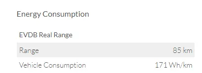
From the energy available from our designed battery pack we can estimate range as
RANGE = Battery Capacity / Energy per Km = 18000 [KWh]/171 [Wh/Km] = 105.3 Km
Results :
- Hence we can see the improvement in mileage around 20Km from previous available range.
Mechanical Designing Of the Battery Pack :
Safety and reliability are the two key challenges for large-scale electrification of road transport sector. Current Li-ion battery packs are prone to failure due to reasons such as continuous transmission of mechanical vibrations, exposure to high impact forces and, thermal runaway. Robust mechanical design and battery packaging can provide greater degree of protection against all of these. BTMS & BMS Plays vital role in this system to safely operate the pack.
Before starting the battery pack construction each cell has to be checked for it's rated/specified voltage across it's terminals. After ensuring the voltage we can be sure that the cell is healthy and it's SOC is fine.
A Mechanical design of the battery pack includes the following:
- Battery cell : I have taken Lithiumwerks ANR26650M1B Cell to design battery pack with 3.3V,2.56 Ah capacity.
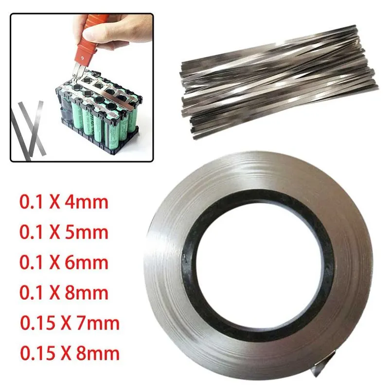
- Nickel strips & spot welder : We use nickel strip to connect the cells in 7S3P to make a module & later Connect the module in 15S7P Configuration to make the battery pack. We use spot welder to connect all the strips to the cells. Depending on the current carried by the strips we take different sizes of nickel strips.

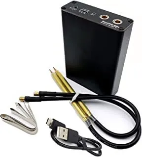
SPOT WELDER : This is a portable spot welder to weld nickel strip on top of cells.

- Battery pack with Holder: It provides space between cells which allows air to flow also thermal conductivity between cells reduces, it provides mechanical support and holds all the cells together.

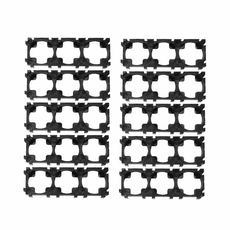
AIM : We have to make a battery pack of 15S7P with 7S3P Module Connections.
We have 3p cells & 7s cells as below
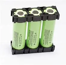
MODULE :
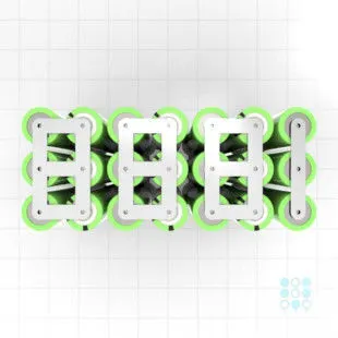
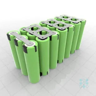
We Connect each 7S3P Module (which is made up of individual cells) in 15 Series & & Parallel Configuration which ultimately forms our Battery pack. Below is the module pack with 7s3p connections.


Battery Pack :
Above modules are to be connected in 15s7p configuration for our battery pack. Below is pictorial representation of the battery pack with 15s7p connections with 15 series modules in horizontal and 7 parallel modules vertical forming 15s7p matrix of the pack.
FIGURE : ONE MODULE OF 7S3P CONFIGURATION.
FIGURE : Battery Pack of 18KWh with 15 series 7 parallel connections(Pictorially) with each module of 7S3P Configured cells.
- BMS(Battery Management System) :
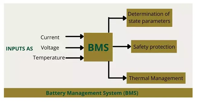
It is well known that BMS(battery management system) is essential in lithium-ion battery systems.It manages real-time control of each battery, communicates with external devices, manages SOC calculations, measures temperature and voltage, and so on. It fetches the information from different sensors in entire pack to calculate and optimize the usage of energy. The selection of BMS determines the quality and life of the final battery pack. A battery management system (BMS) usually includes:
Main Protection Circuit : To protect the pack from failure conditions
- Key features of BMS
- Prevent over current, over/under voltage, over/under temperature and other unsafe conditions
- By analog monitoring IC execution, the IC can monitor the temperature, current and voltage levels of the cell/cell stack
Battery Balancing : To balance Cells and prevent them from overcharge/over discharge / under utilization.
- Battery imbalance can shorten battery life
- The current absorption is not uniform, the heat load is not uniform and the battery is not well matched
- The battery balance circuit tries to balance the battery charge to keep all the batteries in series at the same level
Secondary Protection Circuit :- Redundancy protection mainly prevents overvoltage and can increase overcurrent and overtemperature protection
- Usually through a chemical fuse;
- It will permanently shut down the battery pack
Measurement of Fuel : To measure SOC ,Temperature of the pack, Range Calculation according to the available capacity of the pack- Digital monitoring integrated circuit can feedback the battery capacity
- Three commonly techniques used for determining residual capacity battery include:
- 1.Voltage induction – Most primitive
- 2.Column counting – Measures the capacity used and subtracts from the total capacity known
- 3.Impedance tracking – The ability to calculate impedance based on the battery
 Advantages :
BMS can protect a battery packs from various events, depending on what hardware is selected or required for a particular application.For example, it can protect against undesirable current (A), voltage (V), and temperature (C) events.The BMS tracks any abnormalities in the battery, such as what protection has been activated and how much power/capacity is left when the battery is charged and discharged.They can also help achieve cell balance and other cell maintenance and optimization functions.
NOTE :
It should be noted that when a BMS sends a request, it needs to allow sufficient response time for subsequent processing intelligence.More importantly, the CURRENT overcurrent protection strategy for the BMS must be coordinated with the vehicle controller and the load intelligent controller. Discordant strategies produce the unpleasant phenomenon in which strategies work well but often fail
- Different Sensors like Thermistors,Current Sensor etc.., :
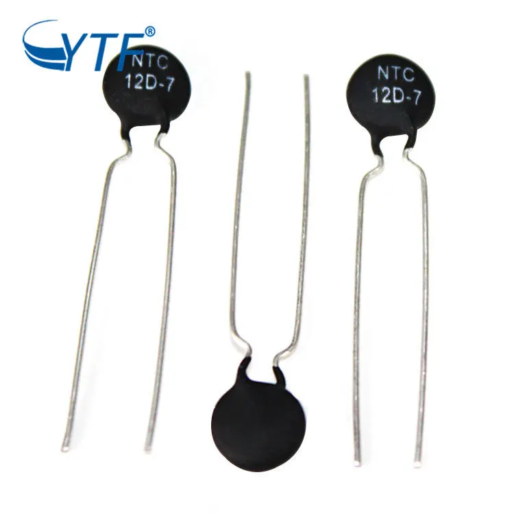
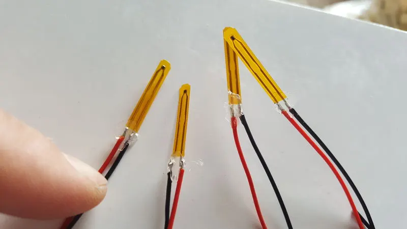
Thermistor, a sensor used to measure temperature of cells & pack. NTC thermistor temperature sensors are a key component in Li-Ion battery charging and safety. They provide critical temperature data required to keep the Li-Ion battery in the optimum condition during the charging cycle. Careful management of temperature during charging prolongs battery life and avoids hazards inherent to Li-Ion batteries.
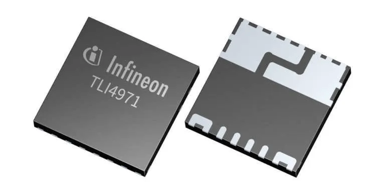
Current Sensor ,To sense current in the pack. This IC is embedded in BMS board as current sensor.
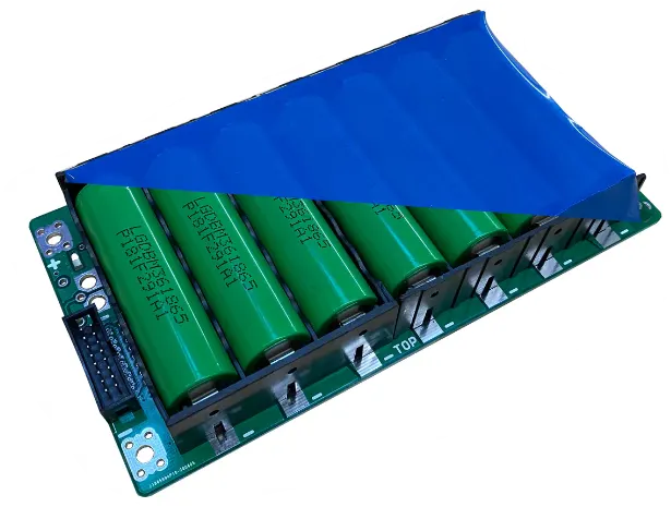
- PVC shrink wrap : The name indicates that once it is wrapped around the battery pack & heated it shrinks and gets attached to the module. After connections made we use shrink wrap to cover the pack from external dust,water contact etc..,

Figure : PVC shrink wrap & module wrapped by using it.
- Insulating paper : To insulate between cells terminals. To ensure protection against voltage ,short circuit.


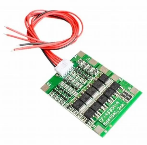
- Connectors and wires : We use connectors & wire to connect BMS board to all the cells . Also sensors from all the cells are connected to BMS board through thin wires & connectors. Below we see BMS board with connecting wires, those wires come from different sensors e.g: Thermistor etc,.
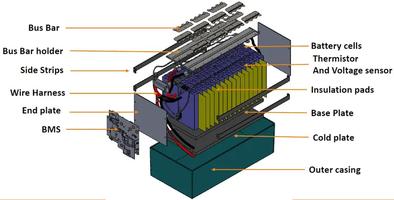
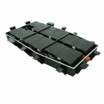
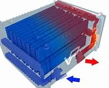
- Battery pack Enclosure : After pack is complete we have to place the pack in an enclosure which acts as outer structure and protects the pack from mechanical vibrations and injury. It gives the additional protection to the pack. Cooling system is also integrated with the enclosure. It holds entire hardware in a single casing.
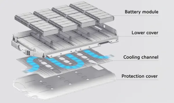
- Battery Cooling System or Battery Thermal Management System : As the pack discharges and charges continuously, large amount of heat is generated in the pack. But we have to dissipate the heat completely and maintain optimum operating temperature in the pack which improves efficiency and life cycles of the cells. For our pack air cooling is sufficient to cool the pack where we can use natural or forced air cooling.
CONCLUSION : Hence successfully created 18KWh battery pack & tested the improved range of the Mitsubishi MiEV vehicle.
References : www.ev-database.org
www.lithiumwerksbatteries.com