Week 7 State of charge estimation
EV LIVE BATCH:-21
1.Simulate the 3 test cases from harness dashboard and write a detailed report on the results.
Ans:- In order to simulate 3 test cases from the test harness dashboard, we have to download the files for thr BMS project (Battery Management System) by click on the following link:-
Steps:-
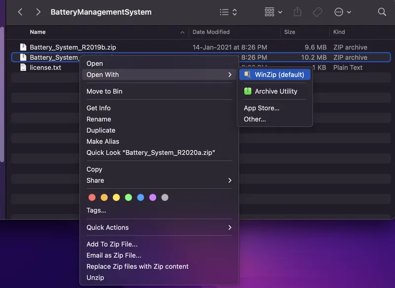
- We will get a Zip file as "BatteryManagementSystem" then unzip that file.

- then we will see there are another two zip files such as "Battery_System_R2019b" & "Battery_System_R2020a".then unzip one file according to the version of MATLAB used.

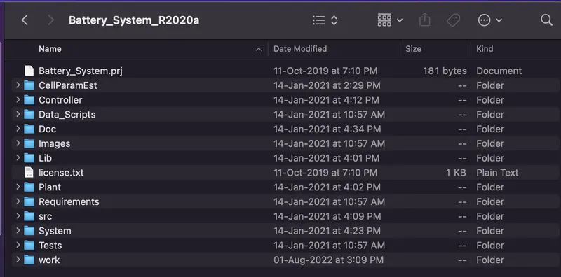
- This project model able to run in those MATLAB have version less than R2019b & trial versions of MATLAB.
- Then open the MATLAB window & set the correct directory path for the BMS project.

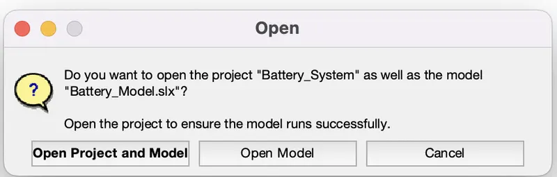
- Then click on "Open Project and Model" & then a new file window will open
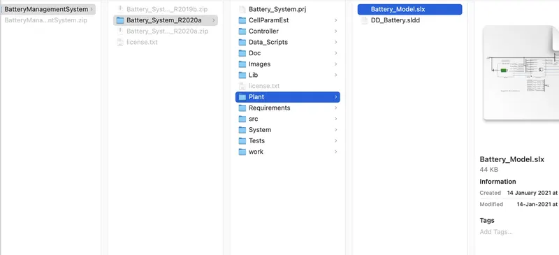
- Then a window will opem automatically for project section containing all folders.
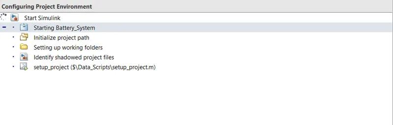
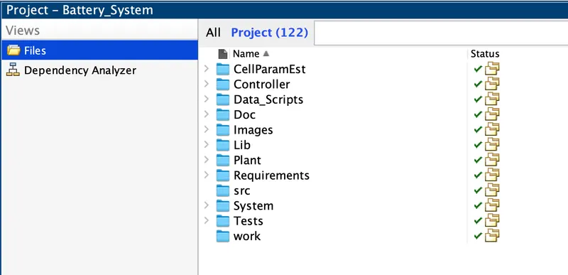
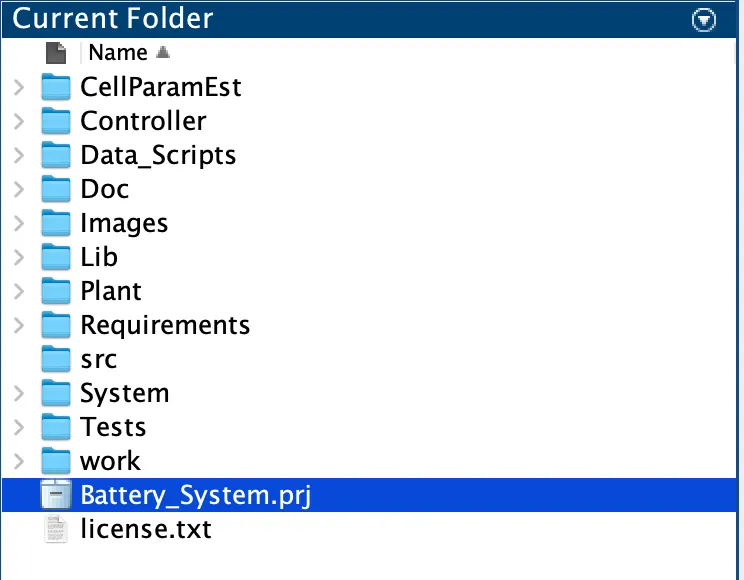
- Then click on "Battery_System.prj" & then click on BMS System from the project shortcurt.
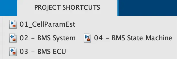
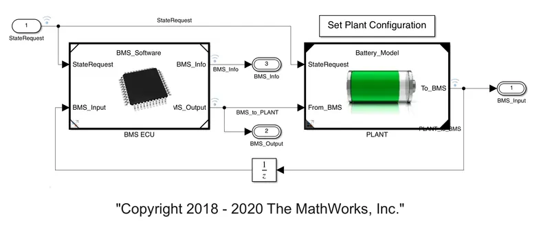
- Then we can see "BMS_ClosedLoop" model will pop-up.
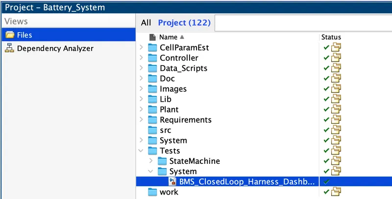
- Then Expand the Test folder then click on System file & then double click on "BMS_ClosedLoop_Harness_Dashboard.slx"
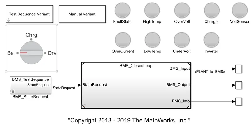
(A) BMS_ClosedLoop_Harness_Dashboard:-
It consists of following blocks:-
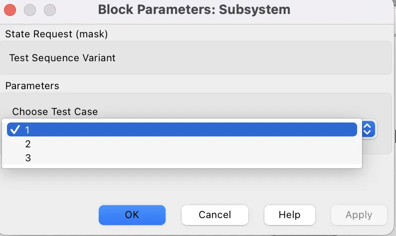
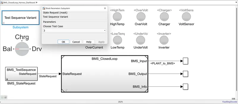
- Test Sequence Variant:- This is a masked subsystem & when we double click on that then we can able to change the no of test cases as there are 3 test cases are available.
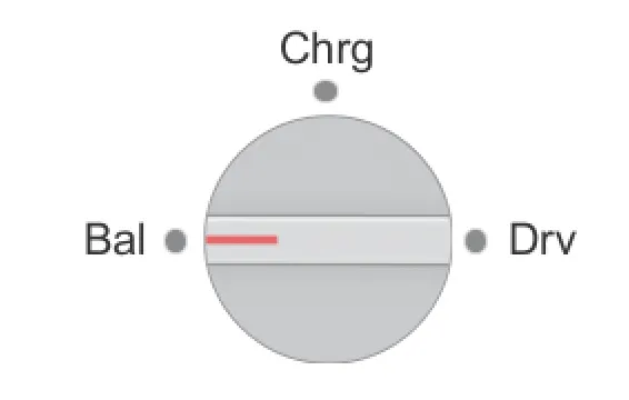
- Manual Variant:- This ia used to change or select the command or test case manually during the simulation.Rotaing switch is one type of Manual Variant selection.
- BMS_StateRequest subsystem provides to state request commands.
- There are 9 no.of Indicating Lamps are taken to show any type of faults occur in the BMS system. Faults are may be High Temperature fault, Low temperature fault, Over voltage fault, Under voltage fault, Over current fault & another 4 indicating lamps are FaultState, Charger, Inverter & Voltage Sensor. Red light will show that there is a fault condition where as Green light will show there is no fault condition.
(B) BMS_ClosedLoop:-
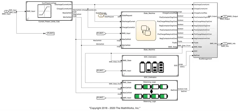
- BMS_ClosedLoop simulink model mainly consists of 2 parts:- BMS ECU & PLANT.
- BMS ECU:- BMS ECU (Electrical Control Unit) which as two inputs such as BMS_Input which is a feedback signal coming from PLANT subsystem through an Unit delay block & StateRequest is the another input coming from the State machine. Then Outputs from the BMS ECU subsystems are BMS_Info & BMS_Output which have current power limit calculation in State Machine, SOC estimation & Cell Balancing as shown in below:-
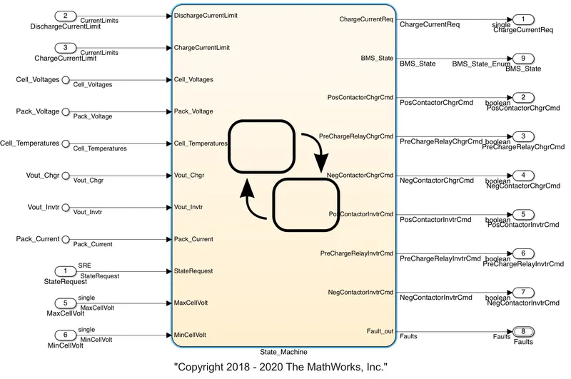
- PLANT:- PLANT subsystem has 2 inputs such as StateRequest coming from the State Machine & another input is From_BMS which comes from the output (BMS_Output) of BMS ECU subsystem.
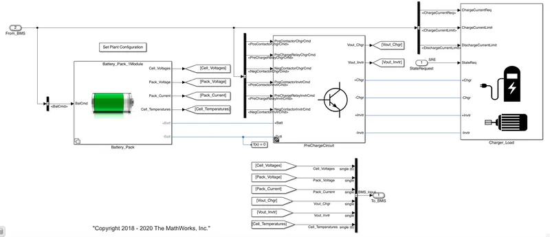
- This PLANT subsystem consists of Battery_Pack, PreChargeCircuit, Charger_Load.
- In the Battery_Pack subsystem, there are two configurations such as 1 Module (6 cells in series) & 16 Modules means 96 cells (there are 16 modules & each module consists of 6 cells in series)
- In the scope, we can see that SOC of module, Cell_Voltages,Pack_Voltage,Pack_Current,Cell_Temperatures etc.
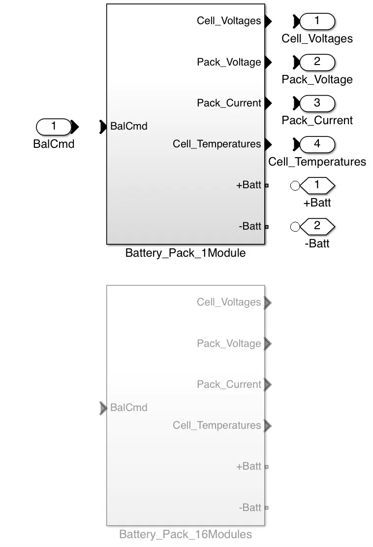
- Here we will choose the Battery 1 pack 1RC which consists of 6 cells in series & this Battery pack module will take less time to simulate as it consists of only 6 cells.
Test Cases:-
- For simulating three test cases, we have to change the test case one by one in "Test Sequence Variant" subsystem
(A) Test Case 1:-
- Choose test case as 1 in the "Test Sequence Variant" subsystem
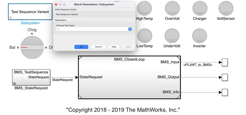
- Now open the BMS_StateRequest subsystem& then again open the BMS_TestSequence subsystem
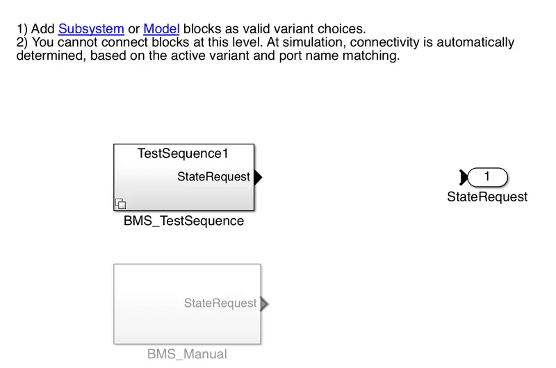
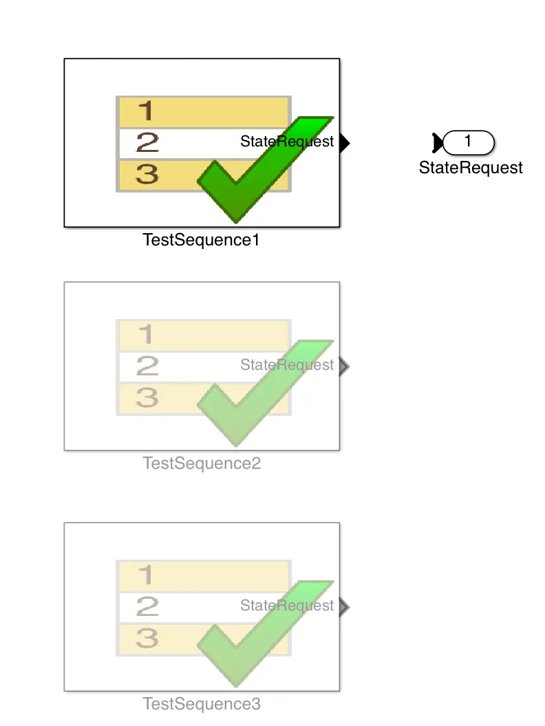
- Here we can see that the TestSequence1 has selected & open that TestSequence1 subsystem
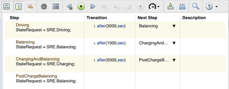
This above Testsequence1 Editor tells us that:
- Intially,Vehicle is in driving condition for 3000sec
- Then after Driving, Balancing of cells occurs for next 1000sec.
- Then Charging & Balancing of Battery pack will occur for next 5000sec
- then PostChargeBalancing of cells will occur after 5000sec till 20000sec which is the simulation time.
Now Run the Harness dashboard under TestSequence1 condition.
Results:-
- After the simulation for 20000sec then we wil see results for TestSequence1 conditions as follows:-
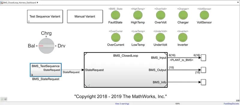
- All the Lamp indicators are green so we can say that there is no faults occur for TestSequence1 condition.
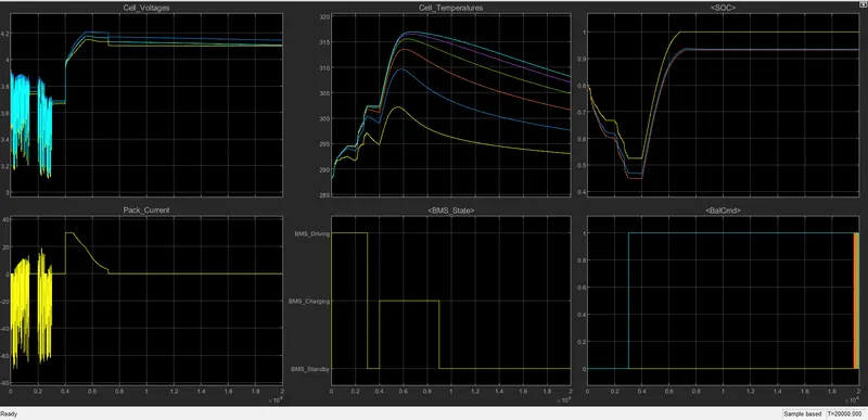
The above graph tells us abot the Cell_Temeperatures, Cell_Voltages, BMS_State, Pack_current, SOC of Battery pack & Balancing of cells.
(i) Driving:- Initially all the cells are in driving mode for 3000sec, so during this period
- As all cells are in driving mode, so the discharging occurs in the cells so cell voltages varry from 3.9 volt to 3.1 volt
- Temperature of the cells increases from 288K (14.85 Degree celsius) to 302K (28.85 degree celsius)
- SOC of battery pack also reduces from 80% to 45%
- we can see the BMS_State is in BMS_Driving condition for 3000sec.
(ii) Balancing:- After 3000sec, Balancing mode for cells get activated for 1000sec, during this period
- We can see that the BMS_State is in BMS_Standby mode for next 1000sec.
- during this Standby mode, the Balancing of cell starts & all seels are having constant voltage of 3.7 volt (approximately)
- Temperature os cells reduces slowly as no current flows through cells during balancing.
- SOC of cell remains constsnt duribg this balancing period & SOC of Battery pack is constant at 45%
(iii) Charging & Balancing:- After balancing, all cells undergo charging & Balancing condition for next 5000sec.
- We can see that, the BMS_State is in BMS_Charging condition for next 5000sec.
- During this charging period, cell voltage increases from 3.7volt ti 4.2 volt(Maximum) in constant current condition of 30 Amp & then again charging starts at constat voltage condition where the current falls from 30Amp to 2.6 Amp (approximately)
- Temperature of cells increases during constant current region upto 317K (43.85 degree celsius) & then starts reducing during constant voltage region. this charging & Balancing of cells occur till 9000sec.
- SOC of battery pack increases from 45% to 100%.
(iv) PostChargeBalancing:- As the simulation time is 20000 sec so this PostChargeBalancing will occur for = 20000-3000-1000-5000 = 11000sec
- During this period, BMS_State is in BMS_Standby mode.
- During standby mode, cell balacing occurs.
- Temperature of cells starts reducing during this period.
- SOC of battery pack remains constant at 100% till the end of simulation.
(B) Test Case 2:-
Now change the Test case as 2 in the Test Sequence Variant subsystem
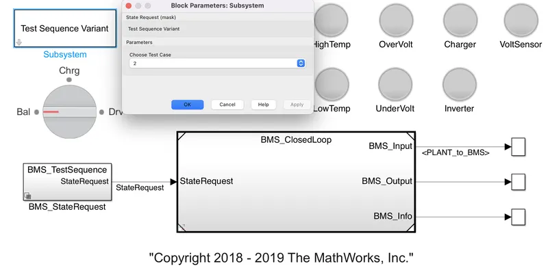
- Now open the BMS_StateRequest subsystem & open BMS_TestSequence
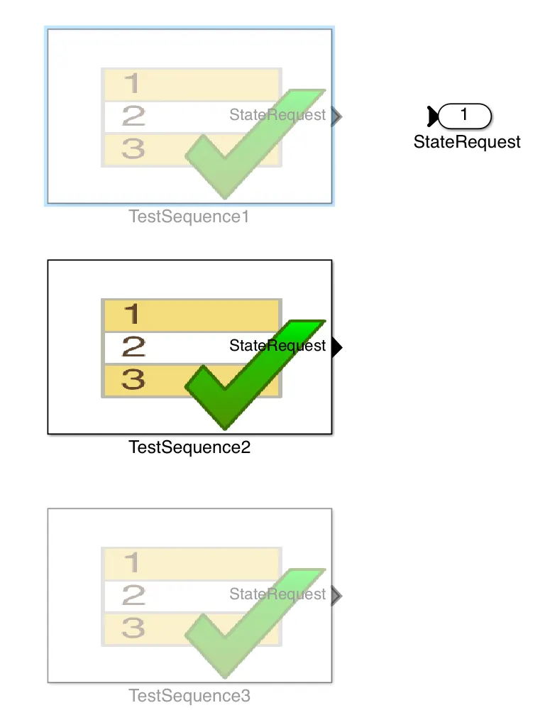
- Here we can see that, TestSequence2 has selected & then open the TestSequence2
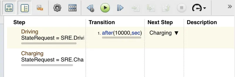
The above Test Sequence Editor tells us that,
- Intially, all cells are in driving mode for 10000 sec
- then Charging mode is activated after 10000sec & it will run for next 10000sec as total simulation time is 20000sec.
Results for 2nd Test Case:-
- After simulating the model under TestSequence2 conditions for 20000sec then we will get:
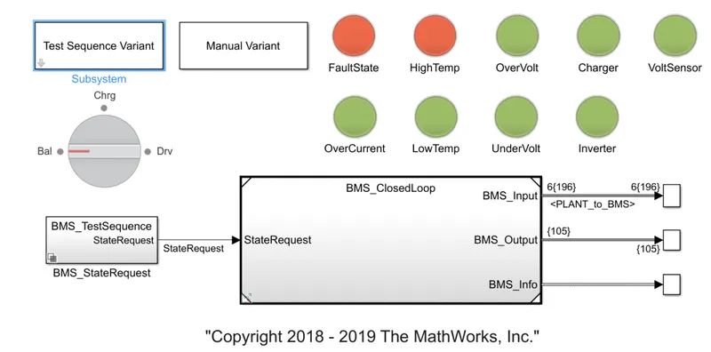
- Here we can see that "HighTemp" indicator shows Red which tells us that there is a fault (Temperature of Battery Pack is very High) occurs after completion of simulation.
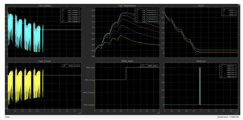 (i) Driving:- Initially, all cells are in driving mode condition for 10000sec, then
- We can see the BMS_State is in BMS_Charging Driving Mode.
- Cell voltages varries in between 3.05 volt to 3.9 volt.
- During driving mode, as the current passes through the cells so the temperature of cells increases gradually from 288K (14.85 degree celsius) to 325K (51.85 degree celsius).
- after 10000sec, SOC of battery pack decreases from 80% to 0% (Fully drained).
(ii) Charging:- After driving mode, all cells undergo for charging mode for next 10000sec, then
- We can see the BMS_State is in BMS_Fault mode as the temperature of every cells in the battery pack is very high (nearly about 52 degree celsius).
- as there is a fault condition in the BMS state, so the battery pack doesn't get charged even it is in the Charging mode.
- So SOC of the battery pack will remains constant at 0%.
(C) Test Case 3:-
- Now choose the Test case as 3 in the Test Sequence Variant subsystem & then go to theBMS_StateRequest subsystem
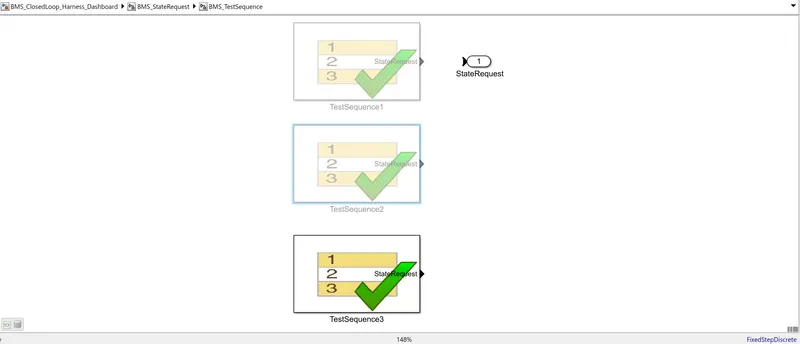
- Now open the TestSequence3
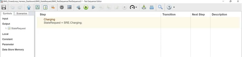
- The above Test Sequence Editor tells us that all cells are in charging mode throught the simulation i.e:- for 20000sec.
- Now run the Harness Dashboard.
Results For TestSequence3:-
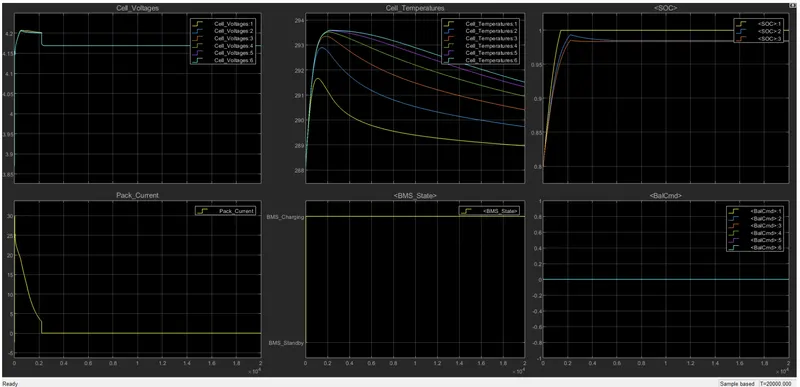
- In the TestSequence3, all cells are in charging mode for 20000sec.
- so the BMS_State is in BMS_Charging mode throught the simulation.
- SOC of battery increases from 80% to 100% & Battery pack reaches at 100% in just 2000sec after starting simulation.
- Battery_pack current increases upto 30 amp during the constant current region & when the battery got 100% charged then contant voltage region will start so the current falls to 2.6 Amp from 30 Amp.
- Cell voltages incraeses upto 4.2 volt initially when the cells starts charging & when the battery is fully charged then voltage falls to 4.17 volt.
Conclusion:-
- We have sucessfully performed 3 test cases for Harness dashboard of a Battery Management Syatem (BMS system)
2.What is coulomb counting? Refer to the above model and explain how BMS implements coulomb counting for SOC estimation ?
Ans:- SOC or State of Charge of a battery pack is defined as the amount of energy remaining in the battery.Basically, SOC of a battery pack is the rate of energy capacity remaining in a battery to the total energy capacity of the battery pack when it is fully charged.
So, There is no direct methods are available to measure the SOC of battery pack. but there are several methods are used to estimate the SOC of a battery pack.
Mainly there are 3 methods are used to estimate the SOC of a battery pach such as:-
- Coulomb Counting Method
- Unscented Kalman Filter method
- Extended Kalman Filter
Coulomb counting method has a wide range of application among these above SOC estimation techniquies.
Coulomb Counting Method:-
- Coulomb counting method measures the discharging current & then it integrates that discharging current over time to get the SOC of battery pack.
- Basically, Coulomb counting method estimate the SOC of a battery pack by considering the value of discharging current & Previous SOC value.
- If the Discharging current is denoted by I(t), Previous SOC is denoted by SOC(t-1) & Current SOC of battery pack is denoted by SOC(t) then SOC can be expressed mathematically as:-
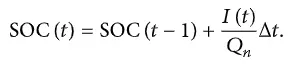
- Where, Δt is the change in time & Qn is the Charge capacity.
- But there are severl factors which affect on the accuracy of Coulomb counting method such as Temperature, discharge current, life cycle & battery history.
- so in order to overcome these problems, a new method is developed named as "Modified Coulomb Counting Method".
Modified Coulomb Counting Method:-
- To improve the coulomb counting method, a new method is proposed named as "Modified Coulomb Counting Method".
- This method uses the corrected current to increases the accuracy of estimation.
- Corrected current is expressed as a quadratic function of discharge current of battery pack as follows.

Where,
- Ic(t) is the Corrected current
- I(t) is the discharging current of battery pack.
- k2,k1 & k0 are constants which can be determined experimentally.
Now, the Modified Coulomb Counting Method can be expressed mathematically as follows:-
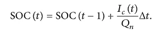
Where,
- SOC(t) is the current time SOC of battery pack
- SOC(t-1) is the previous SOC of battery pack
- Ic(t) is the corrected current value
- Δt is the change in time
- Qn is the charge capacity of battery pack
SOC Estimation in the BMS model:-
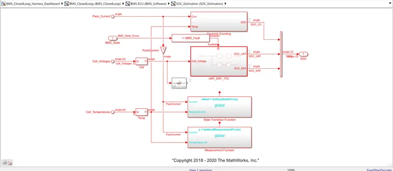
- In order to do that, we have to open the PLANT subsystem & then double click on the SOC_estimation subsystem as follows:
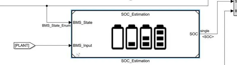
Then we can see there are 3 methods to estimate the SOC of a battery pack such as:-
- Coulomb Copunting Method
- Unscented Kalman Filter Method
- Extended Kalman Filter Method
(A) Coulomb Counting method:-
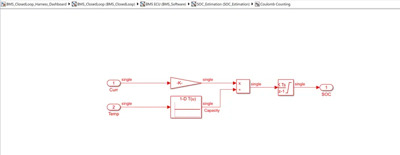
By opening the Coulomb Counting Method subsystem, we will see
 '
'
- Here we can see there two inports which are carrying the discharge current of the battery pack & Temperature of battery pack respectevely.
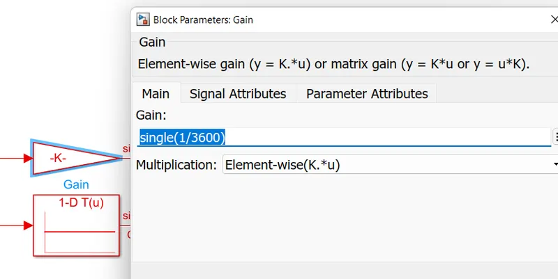
- Discharge current (I(t)) is connected with a gain block having value as single(1/3600) to convert A to Ah.
- Then temperature of battery pack is connected with a 1-D Look Up table which carry the Charge Capacity(Qn) due to change in temperature.
- Then the discharging current (I(t)) get devided by Charge cpacity (Qn) through a Divider block.
- Then the output from the divider block is connected with a Discrete Integrater block which integrates with a gain value of 1 with sample time -1 as follows:
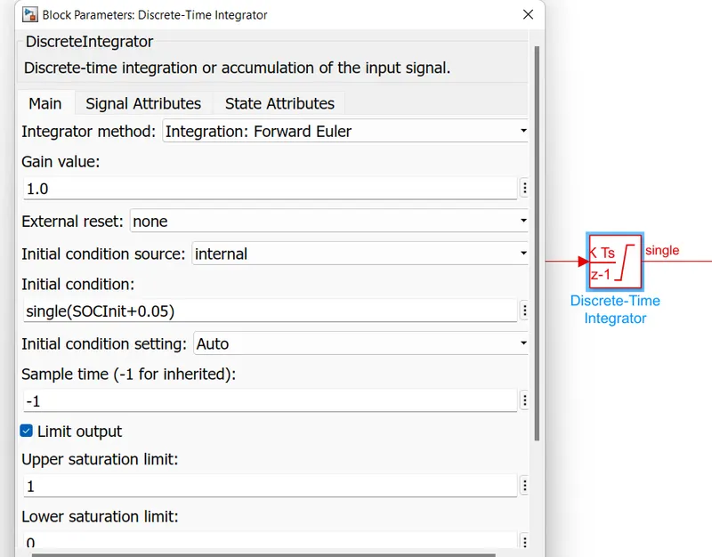
- Upper limit & lower limit has taken as 1 & 0 respectively which means that SOC of battery pack will varry in between 0 to 1 & when multiplied by 100 then it will show the SOC of battery pack in %.
- This is the comple mechanism of Coulomb Counting method for estimating the SOC of a battery pack.