Week 7 State of charge estimation
State of charge estimation
OBJECTIVE:
1.Simulate the 3 test cases from harness dashboard and write a detailed report on the results
2.What is coulomb counting? Refer to the above model and explain how BMS implements coulomb counting for SOC estimation.
#Study 1: Simulate the 3 test cases from harness dashboard and write a detailed report on the results.
In this challenge I have done simulate the 3 test cases from harness dashboard. First I downloaded below link file. Then open it’s on matlab window.
First I had open ‘BMS System’ model at simulink. Then I had open the ‘BMS_closeloop_harness_dashboard’.

BMS_closeloop_Harness_Dasboard model:
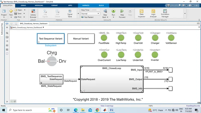
Part1:
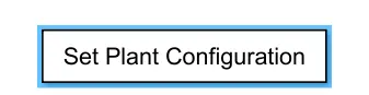
- First select the Set Plant Configuration.
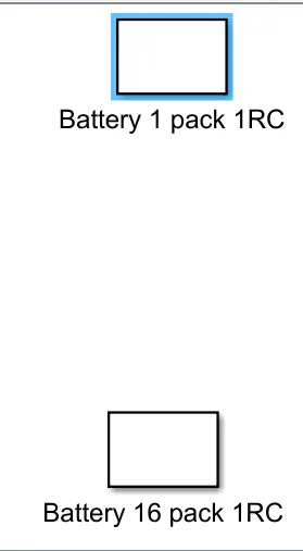
2. I had selected Battery 1 pack 1RC. Then go to the harness model for the simulation.
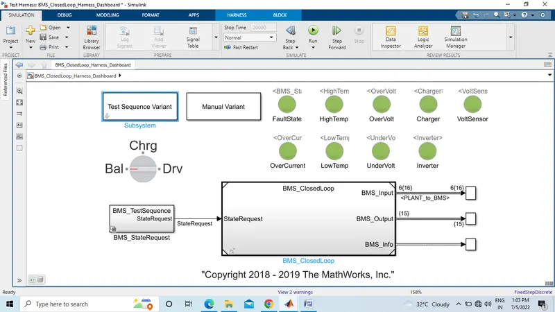
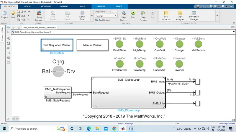
3. This is rotary switch have been used in this model.There are three stage of driving condition, namely-
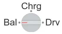
- Driving
- Charging
- Standby
When the simulation begins inititally the vehicle is in driving state and the SOC will decrease for this time period. After a time period of 3000sec the next step is balancing mode and the vehicle is in standby condition. After another 1000sec, rhe vehicle is in charging phase and the battery’s SOC increases almost 100%. The next phase is the postcharging phase in which the vehicle again goes for standby mode.
- Then click on run button of BMS_Closeloop_Harness_model. After compilation is successful scope opens up. The scope consist measurement of cell voltage, cell temperature, SOC, Pack current, BMS State. Here simulation stop time of model is 20,000sec.
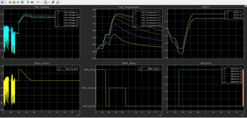
Following the scope result:
- The input cycle can be seen in the BMS_State plot in which the vehicle initially undergoes driving. Then charging till SOC = 90% and then later in standby state.
- During charging battery pack voltage is increase upto 4.2 V.
- The cell temperature increases during the driving and charging cycle and starts falling off in standby mode.
- The SOC drops to less than 50% after the driving cycle and then later put into charging until SOC Reaches 100%.
- The current supplied to the EV during phase can be seen in the current plot.
- Then change the test sequence and observe the result. Now ,we will go for the second test case. For this we have to go test case variant subsystem and select test case 2 from there and click on ‘OK’. Then we have run the system for given simulation time.
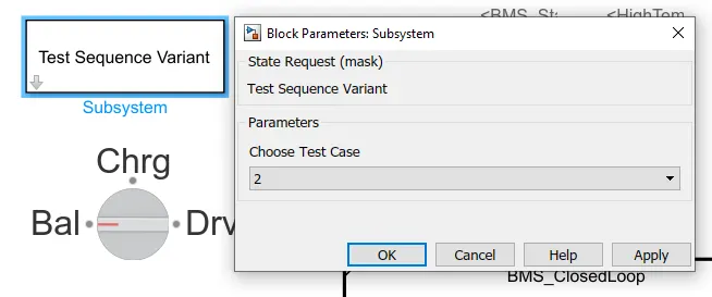
6. After change the test case , run the model again, for understand the difference. simulation time is 20,000 sec. all color indication is green, that’s means vehicle condition is also good in this test case.
Scope Result:
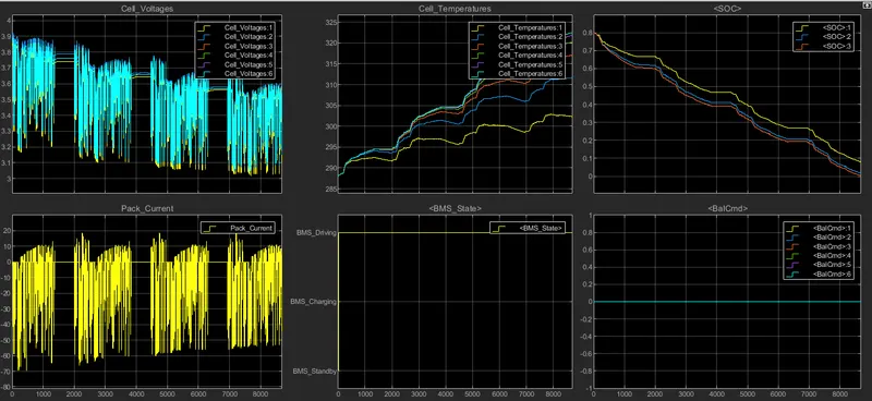
Following scope result for test case two:
- In this test case we can observe maximum cell voltage approx 3.9V and minimum cell voltage 3.2 approx. all cells graph is different. That’s means all the cells condition not accurate in this test case.
- Pack current achieve 20 Amp. That’s means this is high current low voltage circuit. Vehicle drawn high current from battery pack.
- All the Cells temperature approximately similar but not accurate.
- BMS state is in constant nature.
- After 20,000 sec of simulation SOC% is zero. That’s means during simulation battery pack not recharged.
- Then change the test sequence and observe the result. Now ,we will go for the second test case. For this we have to go test case variant subsystem and select test case 3 from there and click on ‘OK’. Then we have run the system for given simulation time.
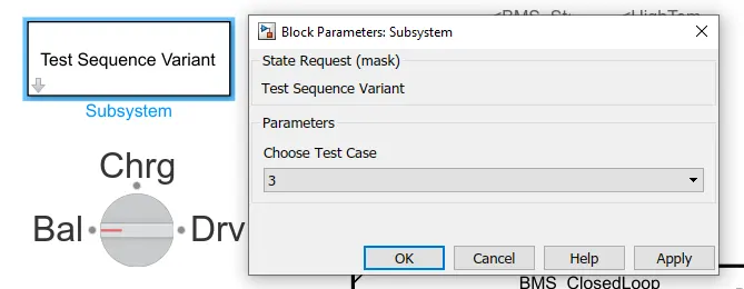
8. After change the test case , run the model again, for understand the difference. simulation time is 20,000 sec. all color indication is green, that’s means vehicle condition is also good in this test case.
Scope Result:
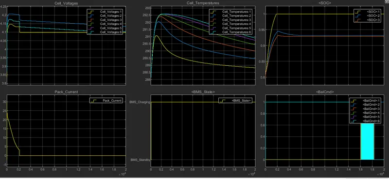
Following scope result of test case 3:
- In this test case we can observe maximum cell voltage approx 4.2V and minimum and all cells gives 4.1 V Constant-Voltage. all cells graph is different. That’s means all the cells condition not accurate in this test case.
- During starting Pack current achieve 30Amp. After certain period of time pack current reduced to zero state. In starting current nature is inrush.
- All the Cells temperature approximately similar but not accurate.
- BMS state is in constant nature.
- After 20,000 sec of simulation SOC% is 50%. That’s means during simulation battery pack is recharged to 100%
#Study 2:What is coulomb counting? Refer to the above model and explain how BMS implements coulomb counting for SOC estimation.
Coulomb Counting:
- The coulomb counting method is expedient for state-of-charge (SOC) estimation of lithium-ion batteries with high charging and discharging efficiencies. The charging and discharging characteristics are investigated and reveal that the coulomb counting method is convenient and accurate for estimating the SOC of lithium-ion batteries. A smart estimation method based on coulomb counting is proposed to improve the estimation accuracy. The corrections are made by considering the charging and operating efficiencies. Furthermore, the state-of-health (SOH) is evaluated by the maximum releasable capacity. Through the experiments that emulate practical operations, the SOC estimation method is verified to demonstrate the effectiveness and accuracy.
- To track the state of charge when using the battery, the most intuitive method is to follow the current by integrating it during cell use. This integration directly gives the quantity of electrical charges injected or withdrawn from the battery, thus making it possible to precisely quantify the SoC of the battery.
- Unlike the OCV method, this method is able to determine the evolution of the state of charge during battery use. It does not require the battery to be at rest to perform an accurate measurement.
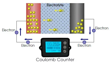
BMS Model coulomb counting for SOC Estimation:
Simulink Model:
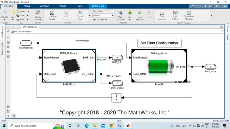
This model is BMS system model. This model have two main subsystem BMS ECU and PLANT, shown in above picture. Set plant configuration also one subsystem for plant configuration.
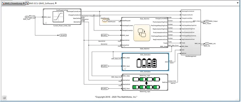
When double click on BMS ECU subsystem then open this subsystem model. This model divide in four subsystem, Current_Power_Limits_Calc, State_Machine, BusManagement, SOC_Estimation, Balancing_Logic.
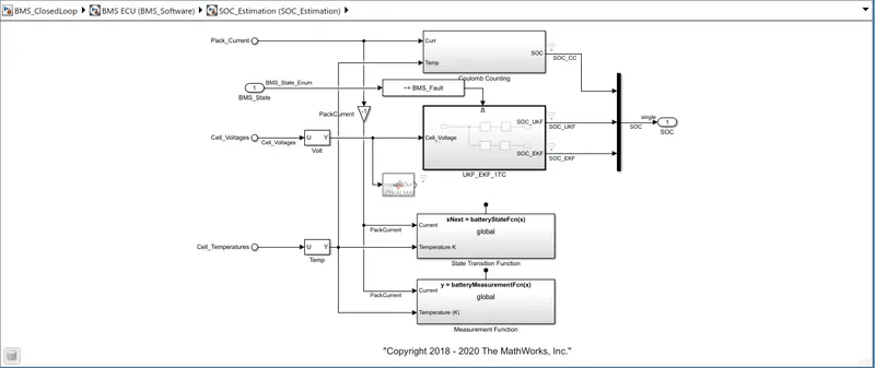
This is the SOC Estimation subsystem model. This model also develop by four another subsystem. One subsystem is enabled subsystem. Coulomb Counting, UKF_EKF_1TC, State Transition Function, Measurement Function.
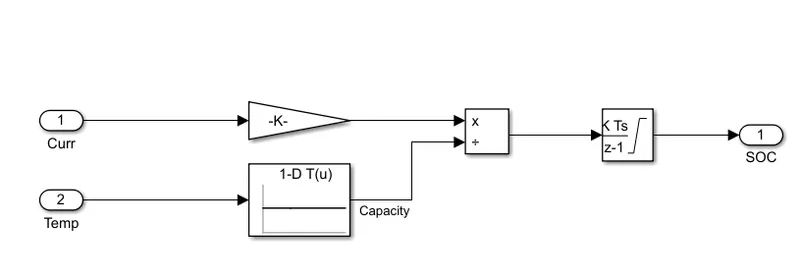
When I double click on coulomb counting subsystem this model is open. This is coulomb counting model for BMS. All the usages blocks discus in below.
Gain block:
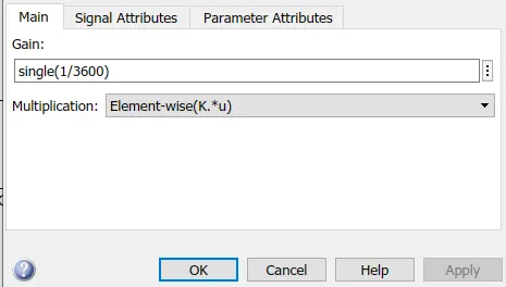
This model have used one gain block. Gain block values is single(1/3600). The Gain block multiplies the input by a constant value (gain). The input and the gain can each be a scalar, vector, or matrix.
1D-Lookup Table:
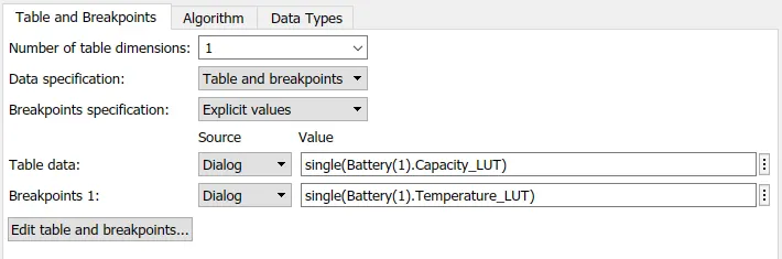
This model have used 1-D lookup table. Lookup Table specification shown in above picture. Perform n-dimensional interpolated table lookup including index searches. The table is a sampled representation of a function in N variables. Breakpoint sets relate the input values to positions in the table. The first dimension corresponds to the top (or left) input port.
Discrete Time Integrator:
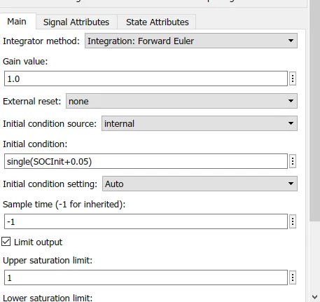
This model used one discrete time integrator block. This block can integrate or accumulate a signal using a forward Euler, backward Euler, or trapezoidal method. Assume that u is the input, y is the output, and x is the state. For a given step n, Simulink updates y(n) and x(n+1). In integration mode, T is the block sample time (delta T in the case of triggered sample time). In accumulation mode, T = 1. The block sample time determines when the output is computed but not the output value. K is the gain value. Values clip according to upper or lower limits.
- Another usages block is two input blocks for current and temperature, one output block for SOC and divide block.