Project 2 Adaptive Cruise Control
ADAPTIVE CRUISE CONTROL
OBJECTIVE:
- Developing Adaptive Cruise Control feature as per the Requirement Document using MATLAB Simulink.
- Adaptive Cruise Control Feature for passenger cars allows the host vehicle to adapt to the speed in line with the flow of traffic. Driving in heavy traffic or keeping a safe distance to the preceding vehicle calls for a high level of concentration. The Adaptive Cruise Control feature can reduce the stress on the driver by automatically controlling the vehicle speed & maintaining a predefined minimum distance to the preceding vehicle. As a consequence, the driver enjoys more comfort & can concentrate on the road little better.
- Using Embedded Coder to generate the code. Follow all the MBD related processes: Requirement Tagging & Traceability, SLDD creation, Configuration Parameter changes, Model Advisor check & Code Generation.
- Tag all the requirement Requirement1, Requirement2, Requirement3 .put all the condition of Adaptive cruise control, and put all the state logic according to question.
TASK:
- First part of model is stateflow chart .this chart have three different mode. ACC_OFF_MODE , ACC_ON_MODE , and ACC_STANDBY_MODE.
- ACC_ON_MODE have six different condition. LeadVehicle_Detected_Follow , LeadVehicle_Not_Detected , LeadVehicle_Detected_Resume , LeadVehicle_Not_Detected_Resume ,LeadVehicle_Speed_LessThan_Set_Speed , LeadVehicle_Speed_equal_Set_Speed.
- Adaptive Cruise Control feature has 3 major modes of operation: OFF Mode, STANDBY Mode & ON Mode. This particular requirement has to be implemented as state machine logic in Simulink.
- A radar sensor is usually at the core of the Adaptive Cruise Control. Installed at the front of the vehicle, the system permanently monitors the road ahead. As long as the road ahead is clear, cruise control feature maintains the speed set by the driver. If the system spots a slower vehicle within its detection range, it gently reduces speed by releasing the accelerator or actively engaging the brake control system. If the vehicle ahead speeds up or changes lanes, the cruise control automatically accelerates to the driver’s desired speed.
- Since Adaptive Cruise Control is a comfort and convenience system, brake interventions and vehicle acceleration only take place within defined limits. Even with Adaptive Cruise Control switched on, it remains the driver’s responsibility to monitor the speed and distance from the vehicle in front.
PROJECT STRUCTURE:
- This is the main subsystem of adaptive cruise control model. This subsystem have nine input and one output.
- Input name is CameraInput_DriveVehicle , RadarInput_DriveVehicle , CameraInput_LeadVehicle , RadarInput_LeadVehicle , CruiseSwitch ,Set_Gap , SetSwitch , Time_Gap ,Set _Speed along with one output.output name is Acceleration_Mode .shown in picture below.
- All the input signal is resolve signal .because all the input signal first time inside the model.
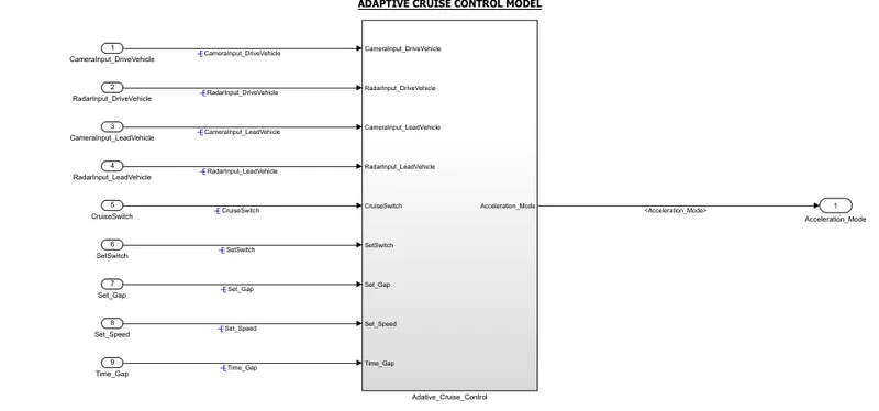
Fig 1: Adaptive Cruise Control subsystem
- This main subsystem divided three more subsystem. Drive Vehicle , Lead Vehicle , ACC_Algorithm accordingly.shown in picture below.
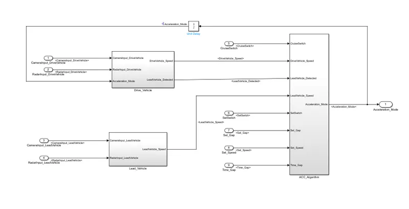
Fig 2: Subsystem Drive Vehicle ,Lead Vehicle ,ACC_Algorithm.
Drive Vehicle:
- This subsystem have three input two output. First used one add block then change the input port of add block. Then connect three input CameraInput_DriveVehicle , RadarInput_DriveVehicle , Acceleration_Mode. Then connect one output DriveVehicle_Speed .after all the connection tap to Acceleration_Mode signal and connect a signal conversion block along with connect LeadVehicle_Detected output block.
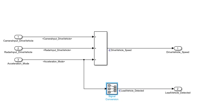
Fig 3: Drive Vehicle subsystem.
Lead Vehicle:
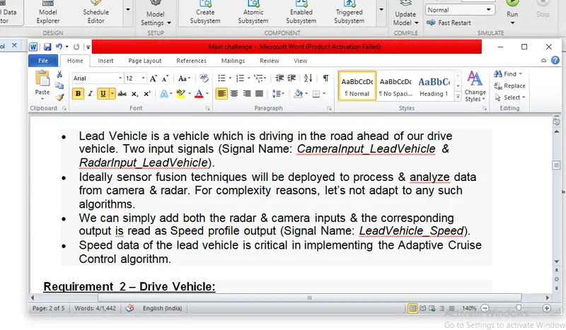
- Lead Vehicle have two input signal and one output signal. First used add block then connect two input block CameraInput_LeadVehicle and RadarInput_LeadVehicle . then connected one output block LeadVehicle_Speed. shown the picture below.
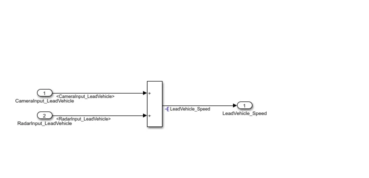
Fig 4: Lead Vehicle subsystem.
ACC_Algorithm:
- Acc_Algorithm subsystem inside have one chart block.this subsystem have eight input signal and one output signal. Input signal is CruiseSwitch , DriveVehicle_Speed , LeadVehicle_Detected , LeadVehicle_Speed , SetSwitch , Set_Gap , Set_Speed , Time_Gap.all the input signal is propagated signal because all the signal is second time input it. Along with one output Acceleration_Mode ,output signal also propagated singal.
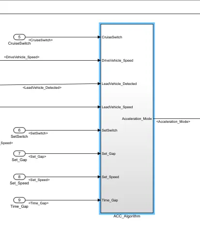
Fig 5: ACC_Algorithm subsystem.
ACC_Logic:
- Inside the ACC_Algorithm subsystem have one state flow chart. This chart connected with eight input propagated signal and one output signal.picture shown in below.
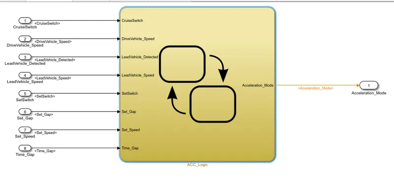
Fig 6:ACC_Logic stateflow chart.
StateFlow Chart:
- This main stateflow chart inside the chart model.this stateflow chart have three different mode ACC_ON _MODE , ACC_OFF_MODE , ACC_STANDBY MODE. ACC_ON_MODE have six different stateflow condition.
- When CruiseSwitch is 0 then acc is go to off condition .when SetSwitch is 0 then acc is go to standby mode condition.when SetSwitch equal to 1 then acc go to on condition.
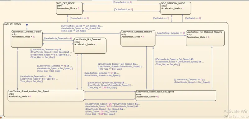
Fig 7: Stateflow chart.
CONDITION:
- [(DriveVehicle_Speed == Set_Speed) && ...
(LeadVehicle_Speed >= Set_Speed) && ...
(Time_Gap >= Set_Gap)]
- [(LeadVehicle_Detected==1) && ...
(DriveVehicle_Speed == Set_Speed) && ...
(LeadVehicle_Speed >= Set_Speed) && ...
(Time_Gap >= Set_Gap)]
- [(LeadVehicle_Detected == 1) && ...
(LeadVehicle_Speed < Set_Speed) || ...
(Time_Gap < Set_Gap)]
- [(LeadVehicle_Detected == 1) && ...
(LeadVehicle_Speed < Set_Speed) || ...
(Time_Gap < Set_Gap)]
- [((LeadVehicle_Speed*1.25>=DriveVehicle_Speed) && ...
(LeadVehicle_Speed * 0.75<=DriveVehicle_Speed)) && ...
(DriveVehicle_Speed < Set_Speed) && ...
((Time_Gap<=1.25*Set_Gap) && ...
(Time_Gap >=0.75*Set_Gap))]
- [(LeadVehicle_Speed
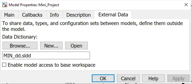
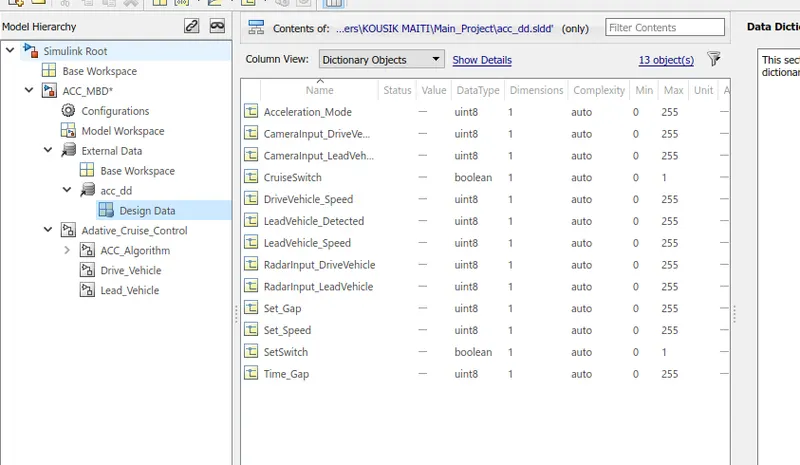
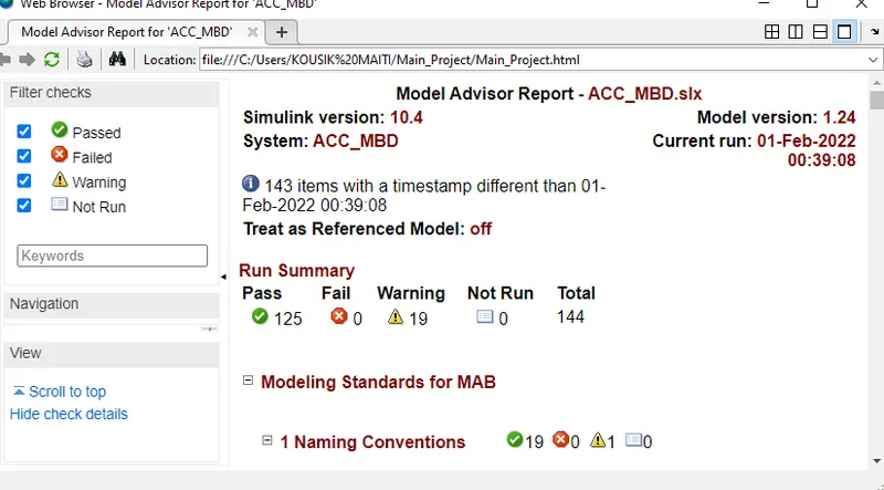
(LeadVehicle_Speed (Time_Gap == 0.75*Set_Gap)] (DriveVehicle_Speed == Set_Speed)] (LeadVehicle_Speed > DriveVehicle_Speed) || ... (Time_Gap >= Set_Gap)] (LeadVehicle_Speed > DriveVehicle_Speed) && ... (Time_Gap >= Set_Gap)] (DriveVehicle_Speed <= Set_Speed)] (LeadVehicle_Speed > DriveVehicle_Speed) || ... (Time_Gap >= Set_Gap) 8.[(DriveVehicle_Speed < Set_Speed) && ... (LeadVehicle_Speed > DriveVehicle_Speed) || ... (Time_Gap >= Set_Gap)] 9.[(DriveVehicle_Speed < Set_Speed) && ... (LeadVehicle_Speed > DriveVehicle_Speed) && ... Signals & Calibration Data List: Signal / Calibration Name Signal Type Data Type Dimension Min Max Initial Value Units CameraInput_LeadVehicle Input Uint8 1 0 255 - - RadarInput_LeadVehicle Input Uint8 1 0 255 - - CameraInput_DriveVehicle Input Uint8 1 0 255 - - RadarInput_DriveVehicle Input Uint8 1 0 255 - - Time_Gap Input Uint8 1 0 255 - - Set_Speed Input Uint8 1 0 255 - - Set_Gap Input Uint8 1 0 255 - - CruiseSwitch Input Boolean 1 0 1 - - SetSwitch Input Boolean 1 0 1 - - Acceleration_Mode Output Uint8 1 0 255 - - LeadVehicle_Speed Output Uint8 1 0 255 - - DriveVehicle_Speed Output Uint8 1 0 255 - - LeadVehicle_Detected Output Uint8 1 0 255 - - Creation of Simulink Data Dictionary file (SLDD): Fig 8:Simulink Data Dictionary Dialog box. Fig 9:Model workspace sldd Design data file (all the required input , output signal and parameter ) MAB Guidelines Check For Model Explorer: A check is performed using ‘Model Advisor’ tool in Simulink to see whether the developed model meets the modeling standards for MAB. First go to model advisor and click on ‘MAB’ then run the programme. Fig: 10 MAB guidelines model explore check. Requirement Tagging of Simulink Model: The requirements ‘Requirement 1– Lead Vehicle’ and ‘Requirement 2 – Drive Vehicle’as provided in the Requirements Word document are tagged to their corresponding subsystem in the Simulink Model. The steps involved in tagging a requirement in the Simulink model is to first highlight the requirement statement in the Word document, then right click on the subsystem in the model that has to be tagged, then select ‘Requirements’ and then ‘Link to Selection in Word. Fig:11 Requirement Tagging Requirement1 word file: Embedded Coder (Code Generation): Using embedded coder convert the simulnik model as a ‘c code’ file. This file is code generation file. Go to embedded coder then click on building option. Then c code file automatically was created. Fig 12: C Code file(using Embedded coder) AIM OF THE PROJECT: AIM of the project is create the adaptive cruise control model for vehicle.Adaptive Cruise Control Feature for passenger cars allows the host vehicle to adapt to the speed in line with the flow of traffic. Driving in heavy traffic or keeping a safe distance to the preceding vehicle calls for a high level of concentration. The Adaptive Cruise Control feature can reduce the stress on the driver by automatically controlling the vehicle speed & maintaining a predefined minimum distance to the preceding vehicle. As a consequence, the driver enjoys more comfort & can concentrate on the road little better. JUSTIFICATION: