Week -2
Aim:
- Make a Simulink model of Doorbell using solenoidblock with the following details.
- Use a thermistor to sense the temperature of a heater & turn on or turn off the fan as per the below conditions.
Doorbell using solenoid:
Working Principle:
- A solenoid is a very simple component, that includes a coil of wire that is covered around a core made out of a metal. When a current is applied to the solenoid, it has the effect of assembling a consistent magnetic field. Electricity changes to magnetism then it changes to electricity and, therefore, these two forces are united into one.
- The solenoid is a electromagnet.on passing through the conducting wires a magnetic field is generated around it which attract magnetic materials. This phenomenon is used in the door bell. When the switch is on then current is passes through the circuit , existing the electromagnet pulling the plunger towards the metal position. This producers a ringing sound.
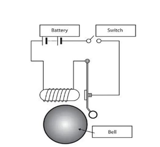
- In the above arrangement, when the switch is closed the electromagnet receives electrical power from the battery and pulls the metal arm to hit the bell producing sound.
- Create a situation where the switch is closed for 2 seconds and then released. Observe the physical movement of the plunger
- As we know the circuit to be closed in the 2 second interval. When switch block is clock electromagnet receives electrical power from the battery and pulls the metal arm to hit the bell producing sound.
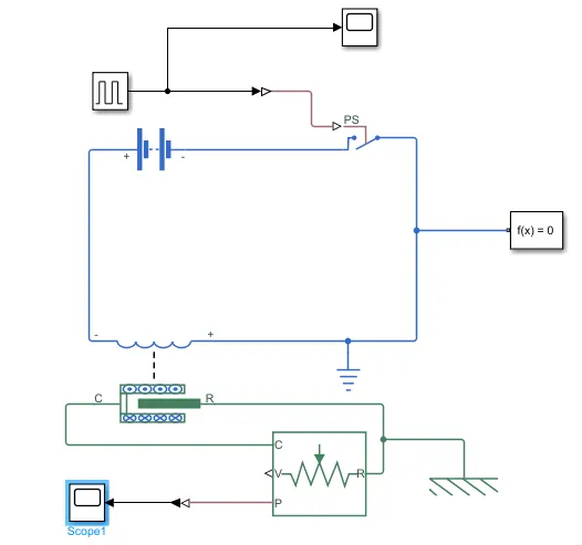
Fig 1: Simulink model of Solenoid Doorbell.
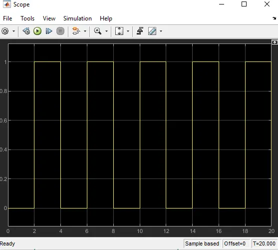
Fig 2: Pulse Generated pattern given as a input. This cycle repeats for 20sec.
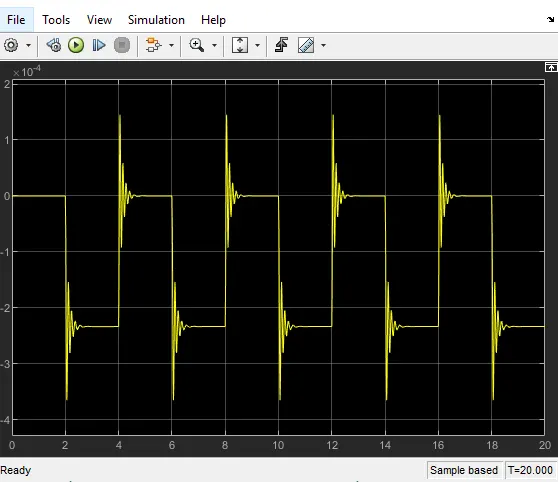
Fig 3: when switch block is closed due to electromagnetic interface graph.
Explanation:
- Solenoid block +ve side connected with battery –ve side and –ve side of battery connected with solenoid +ve side. Solenoid block ‘c’ terminal connected with ideal translational motion sensor c terminal and solenoid ‘R’ terminal connected with ideal translational motion sensor ‘R’ terminal.
- Ideal translational motion sensor is used this block measures velocity or displacement in a mechanical translational network. The sensor is ideal since it does not account for inertia, friction, delays, energy consumption, and so on.The physical signal ports V and P report the velocity and position, respectively, of port R relative to port C. The measured velocity is positive when the velocity at port R is greater than the velocity at port C. ‘P’ terminal connected with scope through ps Simulink converter.
- Battery This block models a battery. If you select Infinite for the Battery charge capacity parameter, the block models the battery as a series internal resistance and a constant voltage source. If you select Finite for the Battery charge capacity parameter, the block models the battery as a series internal resistance plus a charge-dependent voltage source.
- Pulse generator use for Time-based is recommended for use with a variable step solver. Pulse generator connected with switch block and scope. Pulse generator passes the generated signal through the switch. Pulse generator amplitude is 1 ,period of time 4sec and pulse width 50% and phase delay 2sec.
- Switch block represents a switch controlled by an external physical signal. If the external physical signal PS is greater than the threshold, then the switch is closed, otherwise the switch is open.
- Simulink PS converter Converts the Simulink input signal to a Physical Signal.
- PS Simulink converter converts the physical signal to a Simulink output signal.
- Electrical Reference A model must contain at least one electrical reference port (electrical ground).
- Mechanical Translational Reference This block represents a mechanical translational reference point, that is, a frame or a ground. Use it to connect mechanical translational ports that are rigidly affixed to the frame (ground).
Fan Controlled by Thermistor:
Working Principle:
In an NTC thermistor, when the temperature increases, resistance decreases. And when temperature decreases, resistance increases. Hence in an NTC thermistor temperature and resistance are inversely proportional. These are the most common type of themistor.
The relationship between resistance and temperature in an NTC thermistor is governed by the following expression: R(T) = R0*exp(B*(1/T-1/T0))
Where:
- RT is the resistance at temperature T (K)
- R0 is the resistance at temperature T0 (K)
- T0 is the reference temperature (normally 25oC)
- β is a constant, its value is dependant on the characteristics of the material. The nominal value is taken as 4000.
If the value of β is high, then the resistor–temperature relationship will be very good. A higher value of β means a higher variation in resistance for the same rise in temperature – hence you have increased the sensitivity (and hence accuracy) of the thermistor.
Thermistor is a sensor which is used to measure the temperature of the surrounding by comparing it with a known temperature and resistance values. The conditions are:
0-10 seconds 20 degree Celsius
10-30 seconds 27 degree Celsius
30-50 seconds 23 degree Celsius
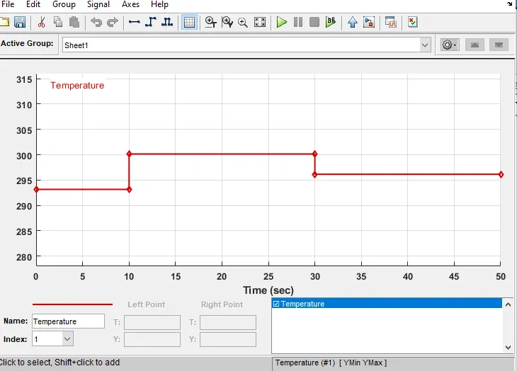
Fig 4: Input signal corresponding to above parameter is given using signal builder block.

Fig 5: Simulink model
The condition is such that, the fan should be turned on when the temperature sensed is greater than 25 degree Celsius(298 kelvin).to fulfil this objective we use a voltmeter to find the voltage of the circuit at different temperature. It is found that voltage at 25 degree Celsius is 0.01189. then switch block threshold value is 0.01189. the switch configured such way that , it is open when less than 0.01183 (temperature less than 25 degree Celsius).when it is greater than threshold value switch is closed.
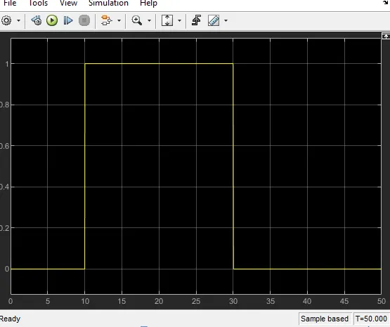
Fig 6: output graph of switch. Only 10-30 sec is fan is turn on.
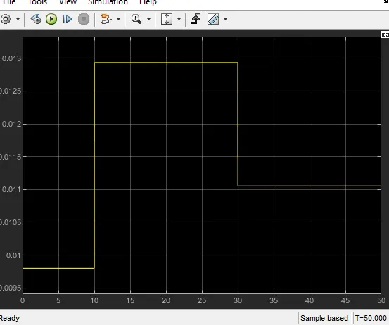
Fig 7: Voltage sensor passes input, simulation time of fan.
EXPLANATION:
- Thermistor ‘A’ terminal connected with controlled temperature source ‘B’ terminal. Thermistor +ve terminal connected with battery +ve terminal. And –ve terminal connected with voltage sensor.This block represents an NTC thermistor using the B-parameter equation. The resistance at temperature T is given by R(T) = R0*exp(B*(1/T-1/T0)) where R0 is the Nominal resistance at the reference temperature T0, and B is the Characteristic temperature constant.
- Controlled temperature source ‘s’ terminal connected with signal builder block and ‘A’ terminal connected with thermal reference block.
- Voltage sensor This block represents an ideal voltage sensor, that is, a device that converts voltage measured between any electrical connections into a physical signal proportional to the voltage.
- Simulink PS converter Converts the Simulink input signal to a Physical Signal.
- PS Simulink converter converts the physical signal to a Simulink output signal.
- Electrical Reference A model must contain at least one electrical reference port (electrical ground).
- Battery This block models a battery. If you select Infinite for the Battery charge capacity parameter, the block models the battery as a series internal resistance and a constant voltage source. If you select Finite for the Battery charge capacity parameter, the block models the battery as a series internal resistance plus a charge-dependent voltage source.
- Thermal reference This block represents a reference point in a thermal network where the temperature is equal to absolute zero.