Week 7 State of charge estimation
After the dawnlod model we get below model:
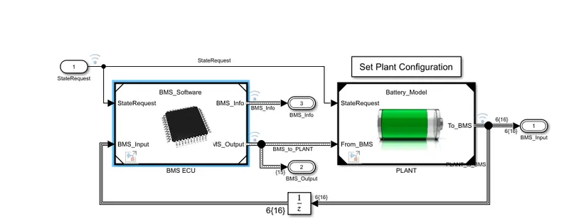
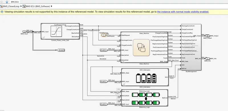
State Machine in the BMS ECU defines the main operating state of the BMS . The state machine has four paraller states
(parallel meaning that they can be active at the same time).
- The first one define the variable BMS_state which indicates standby, driving, charging , and fault. Charging comprises constant current and constant voltage stages.
- The second state switches the fault state ON in case a current, Voltage or tempreature value reaches on unsafe level.
- The third and fourth states define the contactor ON and OFF switching sequence for the charger and inverter.This is needed to avoid an excessively large current incrush at the begining of the charging stage.
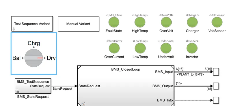
From the above MATLAB model we are simulating 3 test cases from harness dashboard to find out the fault condition in BMS.
And the dashboard where we can get the information related to the faults like over voltage , under voltage, high temperature, over current and inverter related faults . if any fault condition the indicators will turn on .
there is two variant availabe
1. Teat sequence variant
2. Manual variant
this model working on 3 types of mode:
according to the set mode we can get the output graph.
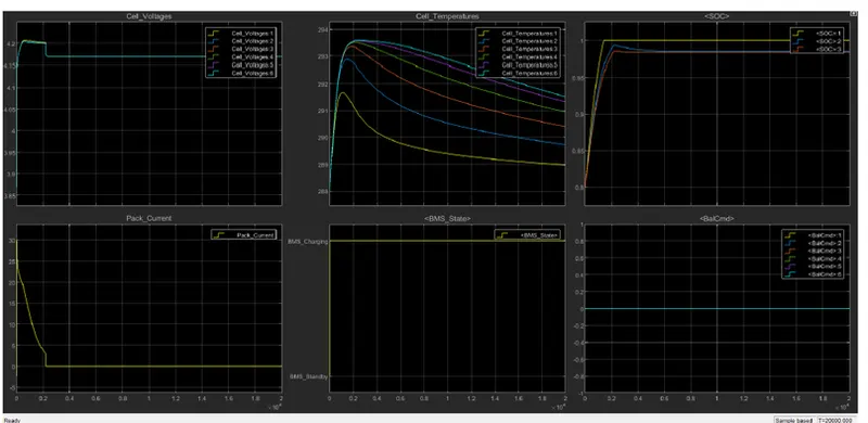
for the simulation we get the output graph.
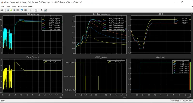
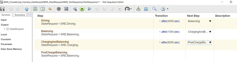
- when simulation starts , the model will in driving condition .
- we observed at 3000 sec model will come on stand by mode.
- after 1000sec it will be on charging condition .
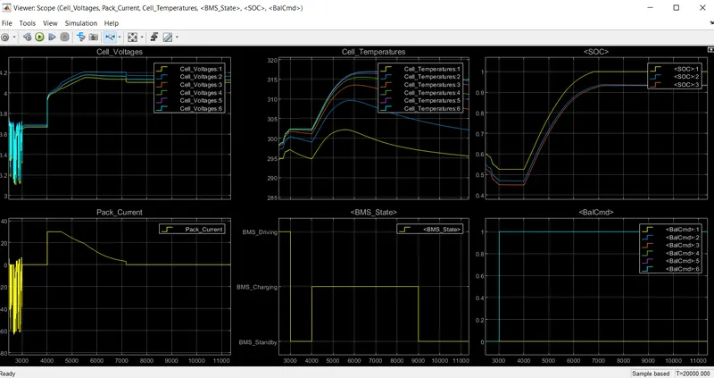
- above graph observed that when voltage raised , tempreature increases . and then balance command on.
- cell tempreature decrease with the model stand by mode.
- driving stage is 0 to 10000 sec .
- after fault occur.
PART B:
It depends on the recording of the current noise only.
The signal is filtered with a high-pass filter with a cut-off frequency of 0.01 Hz
The filter may be either analogue (although the implementation of a good-quality 0.01 Hz analogue filter is difficult) or digital.
The absolute value of the measured current samples is then summed over time.
A steep slope is taken as an indication of rapid corrosion, although it is not possible to calibrate this in terms of an estimated corrosion rate.
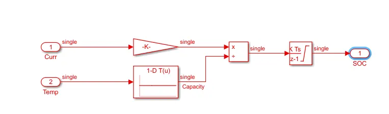
To determine available capacity, coulomb counting relies on the integration of the current drawn from and supplied to a battery over time, τ∈t0t">τ∈ [t0, t], as given by

firstly look at what the SoC is used for.
- capacity of the cell that is remaining (fuel gauge on your phone or electric vehicle)
- an input to estimate the available charge and discharge power capability of the battery
- used in the calculation of State of Health
The accuracy required for these values will determine the accuracy that is required for the inputs to the SoC algorithm. This will impact the selection of:
- components for cell voltage measurement
- voltage sense wires, connectors and connection locations
- current sensor or sensors
- voltage and current measurement channel accuracy
- timing circuit
The State of Charge (SoC) of a battery cell is required to maintain it’s safe operation and lifetime during charge, discharge and storage.
However, SoC cannot be measured directly and is estimated from other measurements and known parameters.
This leads to errors in the estimated SoC and that means it is not possible to fully exploit the full capability of the cell.
Coulomb counting gives a relative change in SoC and not an absolute SoC.
If you measure the current over a given time step you have a measure of the number of Ah that have left or been received by the battery.
The coulomb counting approach then estimates the remaining capacity just by collecting the charge transferred in or out of the battery.
The precision of this approach resorts mainly to a specific measurement of the battery current and an accurate estimate of the initial SOC.
by the above graph
With a pre-known capacity, which might be remembered or initially evaluated by the operating conditions, the SOC of a battery can be estimated by incorporating the charging and discharging currents over the operating terms.
Yet, the releasable charge is still less than the stored charge in the charging and discharging process.
In other terms, there are losses during discharging and charging.
These losses, in complement to the self-discharging, drive accumulating errors. For more accurate SOC estimation, these aspects should be taken into account.
And also, the SOC should be recalibrated on a frequent basis and the declination of the releasable capacity should be evaluated for more accurate estimation.
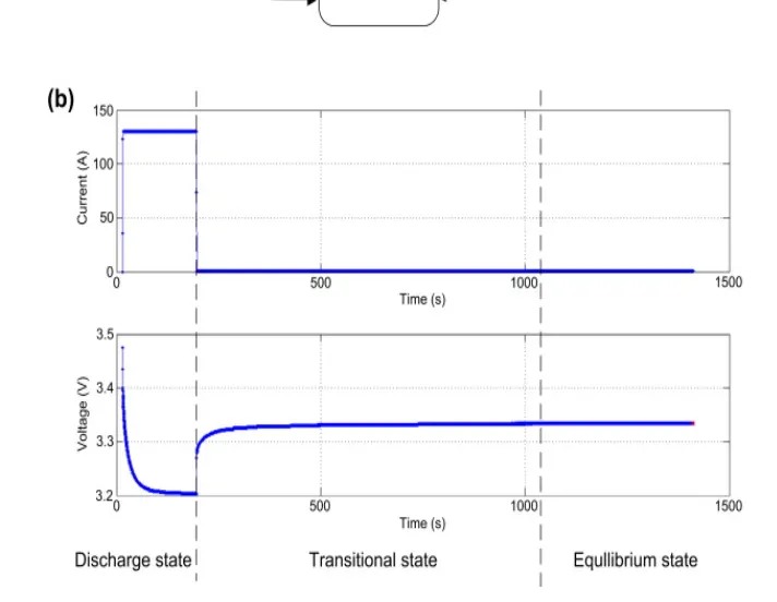
direct voltage measurement based on the EMF and adaptivity of the maximum battery capacity (Qmax), and the EMF as function of SoH are combined.
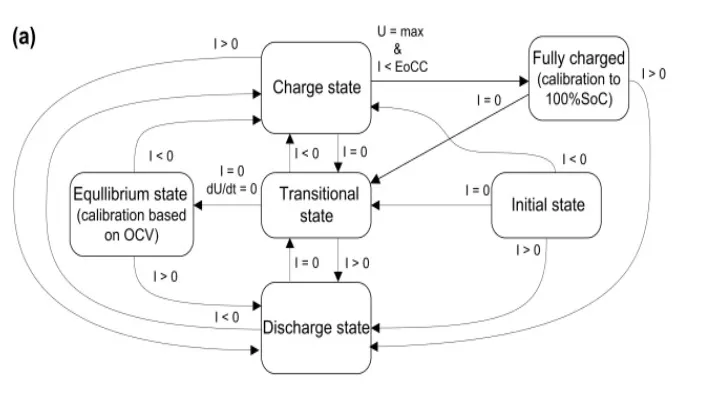
The general principle of the SoC-indication algorithm is illustrated in the form of a state diagram .
The basis of the SoC algorithm is the EMF measurement during the equilibrium state. The algorithm resides in this state when no or only a small current (smaller than defined minimum current Ilim) flows and the battery voltage has fully relaxed from previous (dis)charge currents. The measured battery voltage can be translated into SoC by means of an EMF curve stored in the system.
During current flow larger than Ilim into or out of the battery, SoC indication is based on coulomb counting in either the charge or the discharge state, respectively.
In the discharge state, the influence of the overpotentials on the available capacity is taken into account, as will be explained in more detail below. After current interruption, a voltage prediction method is used in the transitional state to predict the EMF, based on the first part of the voltage relaxation curve.
the predicted EMF is close to the actual EMF and can be used to calibrate the system.
This implies that the influence of errors that integrate over time while integrating charge or discharge current can be compensated for. Moreover, using a voltage prediction algorithm allows the system to proceed to the equilibrium state without having to wait for the battery voltage to stabilize. The predicted EMF can simply be transferred into an SoC value using the stored EMF curve.
Since the SoC is estimated on a relative scale using the EMF curve in equilibrium and the coulomb counter yields an absolute
SoC value in the charge and discharge state, the maximum battery capacity Qmax is needed to translate the absolute values into relative values. An update mechanism for Qmax has therefore been implemented to deal with aging. Moreover, it is shown that updating the stored EMF curve to deal with aging.