Week-6 Challenge: EV Drivetrain
Which types of power converter circuits are employed in electric and hybrid electric vehicle?
Electric vehicle converters requirements
In case of interfacing the Fuel Cell, the DC/DC converter is used to boost the Fuel Cell voltage and to regulate the DC-link voltage. However, a reversible DC/DC converter is needed to interface the SCs module. A wide variety of DC-DC converters topologies, including structures with direct energy conversion, structures with intermediate storage components (with or without transformer coupling), have been published (Lachichi & Schofield, 2006), (Yu & Lai, 2008), (Bouhalli et al., 2008). However some design considerations are essential for automotive applications:
-
Light weight,
-
High efficiency,
-
Small volume,
-
Low electromagnetic interference,
-
Low current ripple drawn from the Fuel Cell or the battery,
-
The step up function of the converter,
-
Control of the DC/DC converter power flow subject to the wide voltage variation on the converter input.
AC to DC converters are most commonly used in Plug-in Hybrid Electric Vehicles (PHEV) & Plug-in Electric Vehicles (PEV). ...
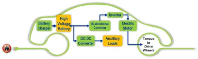
DC-DC converters can be used to interface the elements in the electric power train by boosting or chopping the voltage levels.
There are five main types of converter in this non-isolated group, usually called the buck, boost, buck-boost, Cuk and charge-pump converters. The buck converter is used for voltage step-down, while the boost converter is used for voltage step-up.
Non-isolated converters
The non-isolated converters type is generally used where the voltage needs to be stepped up or down by a relatively small ratio (less than 4:1). And when there is no problem with the output and input having no dielectric isolation. There are five main types of converter in this non-isolated group, usually called the buck, boost, buck-boost, Cuk and charge-pump converters. The buck converter is used for voltage step-down, while the boost converter is used for voltage step-up. The buck-boost and Cuk converters can be used for either step-down or step-up. The charge-pump converter is used for either voltage step-up or voltage inversion, but only in relatively low power applications.
Isolated converters
Usually, in this type of converters a high frequency transformer is used. In the applications where the output needs to be completely isolated from the input, an isolated converter is necessary. There are many types of converters in this group such as Half-Bridge, Full-Bridge, Fly-back, Forward and Push-Pull DC/DC converters (Garcia et al., 2005), (Cacciato et al., 2004). All of these converters can be used as bi-directional converters and the ratio of stepping down or stepping up the voltage is high.
-
DC/DC converters for electric vehicles
The different configurations of EV power supply show that at least one DC/DC converter is necessary to interface the FC, the Battery or the Supercapacitors module to the DC-link.
In electric engineering, a DC to DC converter is a category of power converters and it is an electric circuit which converts a source of direct current (DC) from one voltage level to another, by storing the input energy temporarily and then releasing that energy to the output at a different voltage. The storage may be in either magnetic field storage components (inductors, transformers) or electric field storage components (capacitors).
DC/DC converters can be designed to transfer power in only one direction, from the input to the output. However, almost all DC/DC converter topologies can be made bi-directional. A bi-directional converter can move power in either direction, which is useful in applications requiring regenerative braking.
The amount of power flow between the input and the output can be controlled by adjusting the duty cycle (ratio of on/off time of the switch). Usually, this is done to control the output voltage, the input current, the output current, or to maintain a constant power. Transformer-based converters may provide isolation between the input and the output. The main drawbacks of switching converters include complexity, electronic noise and high cost for some topologies. Many different types of DC/DC power converters are proposed in literature (Chiu & Lin, 2006), (Fengyan et al., 2006).
AC-DC converters
are electrical circuits that transform alternating current (AC) input into direct current (DC) output. They are used in power electronic applications where the power input a 50 Hz or 60 Hz sine-wave AC voltage that requires power conversion for a DC output.
AC to DC converters use rectifiers to turn AC input into DC output, regulators to adjust the voltage level, and reservoir capacitors to smooth the pulsating DC. This video explains how AC is converted into DC.
Types
- Linear devices are simple and relatively inexpensive, but also large and inefficient. They process excess power as heat, which can be problematic for some temperature-sensitive applications.
- Switching devices are more complex AC to DC converters that use a switched-mode power supply (SMPS). A switching regulator shifts very quickly between full-on and full-off states, minimizing wasted energy. Switching converters are more efficient, smaller, and lighter, but also more complicated. They can cause electrical noise problems if not carefully suppressed, and simple designs may also have a poor power factor.
Applications
AC-DC converters are used in computers, televisions, cell phone chargers, and other electronic consumer devices. They are also used in medical, military, and telecommunications equipment; kitchen appliances; industrial machinery; and commercial products that use DC motors.
AC-AC converters
The proposed hybrid frequency ac / ac converter topology is shown for the WPT on-board chargers in Fig. 2. It comprises a front-end filter, series connected two half-bridge resonant inverters, a pair of coupling coils (or a closely coupled transformer in the case of a wired charger) with resonant capacitors, charger, and vehicle battery. The grid-side frequency
and high frequency switching are superimposed through thecoupling coils and fundamental frequency of the energy is transferred to the vehicle-side with a 60 Hz sinusoidal carrier signal. The converter state and switch transitions are presented the behavior of the proposed system in Figs. 3-6. To simplify the
circuit analysis, filter losses are assumed to be negligible, the
input capacitor is assumed to be large enough, and primary side active switches are ideal. The proposed circuit is analyzed when the grid sinusoidal voltage is in positive and negative half-cycles
in the following operation modes, respectively.
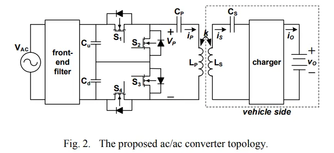
Fig. 2. The proposed ac/ac converter topology.
CONCLUSIONS
In this study, a new ac / ac converter topology is presented for wired or wireless EV charging system. State analysis and analytic equations of the converter are described by the switch
state conditions. Grid and output voltage and current waveforms are presented with primary and secondary resonant tank voltage
and current waveforms at 60 Hz and 85 kHz frequencies. The experimental results are performed with 110 VRMS ac input voltage and 110 VRMS output voltage. It is demonstrated that the grid voltage at 60 Hz frequency can be converted to highfrequency ac voltage required for wireless power transfer with the proposed ac / ac hybrid frequency converter. The other
important result is that the designed converter can be operated with constant frequency without requiring closed-loop control or additional converter stages. The output power of 650 W is
observed at 89 % efficiency and obtained with 0.99 power factor and 1.5 % current THD. The efficiency is expected to be much
higher at rated power as the experimental setup was operated at a much lower power than the rated in this initial proof of concept stage.
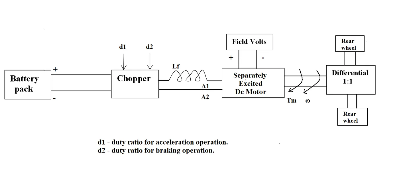
2. An Electric Vehicle's powertrain with 72V battery pack in shown in the diagram below. The duty ratio for acceleration operation is 'd1' and for the braking operation the duty ratio is 'd2'.
The other parameters of the electric vehicle is given below,
Motor and Controller Parameters:
Rated Armature voltage= 72 V
Rated armature current= 400 A
Ra= 0.5Ω, KΦ= 0.7 Volt second
Chopper Switching frequency= 400 Hz
The vehicle speed-torque characteristics are given by the below equation

What is EV steady state speed if duty cycle is 70%?
ANS: we know that :
Motor and Controller Parameters:
Rated Armature voltage= 72 V
Rated armature current= 400 A
Ra= 0.5Ω, KΦ= 0.7 Volt second
Chopper Switching frequency= 400 Hz`ohm`
Duty cycle = .70
Vbat = 72 v
Ω = Vt/ KΦ - Ra/KΦ ^2 .(Tt)
Vt = Vbat * Duty cycle
Vt = 72 * 0.70
= 50.4
putting the value in equation
Ω = Vt/ KΦ - Ra/KΦ ^2 .(Tt)
= 50.4 / .7 - 0.5/0.7 ^2 . (Tt)
= (72 - Ω ) / 1.020
Tt = 70.58 - 0.98Ω
as we know
according to Tv and Tt
= 70.58 - 0.98Ω
= 0.0051 Ω^2 + 0.98 Ω - 45.88
= (Ω - 38.92 ) (Ω+ 231.08 ) = 0
Ω = 38.92 , - 231.08 .
that is the out put but we know that speed can not be negative so we will consider 38.92 rad/ sec . it is called EV steady state condition.
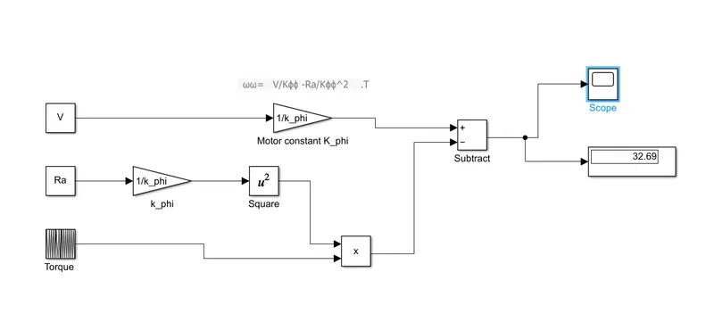
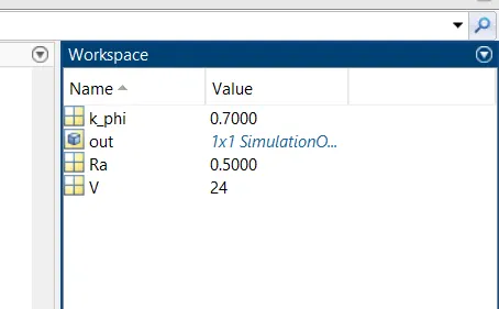
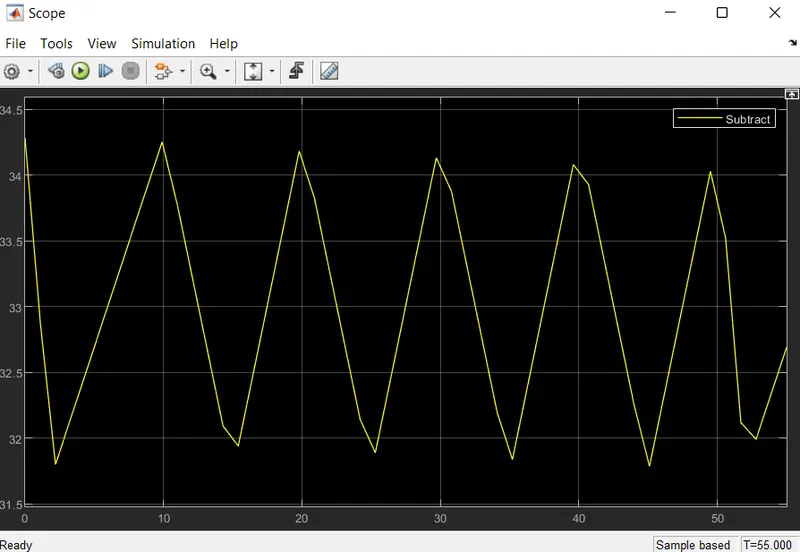
3. Develop a mathematical model of a DC Motor for the below equation using Simulink.
4. Refer to the blog on below topic:
Induction Versus DC brushless motors by Wally Rippel, Tesla
Explain in brief about author’s perspective.
author’s perspective :
1. DC brushless drives require an absolute position sensor, while induction drives require only a speed sensor.
2. Induction machines are more difficult to control. The control laws are more complex and difficult to understand. Achieving stability over the entire torque-speed range and over temperature is more difficult with induction than with DC brushless.
3. The peak point energy efficiency for a DC brushless drive will typically be a few percentage points higher than for an induction drive.
4. The conversion of electrical to mechanical energy is optimally efficient. The device that provides this current control is called an inverter. Without it, brushless motors are useless motors.
5. Unlike the DC brushless rotor, the induction rotor has no magnets. 3-phase induction motor cannot operate from DC; AC is a must.
6. The stators for the 3-phase induction motor and the DC brushless motor are virtually identical. Both have three sets of “distributed windings” that are inserted within the stator core. The essential difference between the two machines is with the rotor.
conclusion is that DC brushless drives will likely continue to dominate in the hybrid and coming plug-in hybrid markets, and that induction drives will likely maintain dominance for the high-performance pure electrics.
7. Add some feedback loops such that the inverter produces the exact frequency that the motor “desires,” and the induction motor is now capable of competing with DC and DC brushless for vehicle applications.