Week 7 State of charge estimation
1. Harness dashboard simulation:
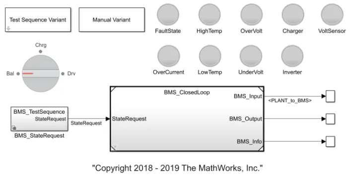
Blocks:
Test sequence variant
Manual variant
Lamps to indicate functioning of fault state, High temp, over voltagge, volt sensor, over current, Low temp, under volt, Inverter. Red lamp means fault occured, Green means No fault.
BMS Test sequence state request
Scope block
BMS closed-loop(Sub-system)
BMS_Closed loop
In this block, two sub-systems are there.
BMS ECU
Plant
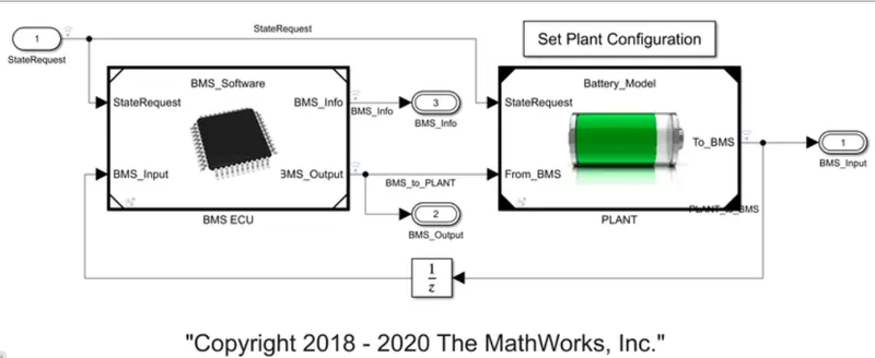
BMS ECU:
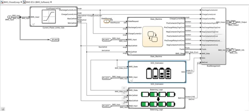
Inside BMS ECU,
current power limit calculation
state of machine block
SOC Estimation block
Cell balancing logical block
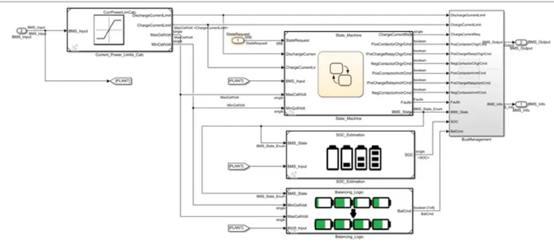
Plant:
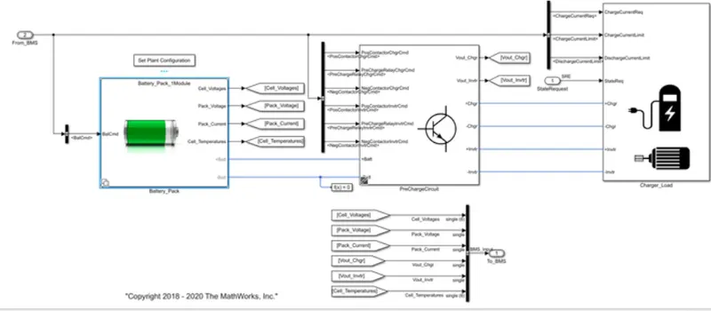
Inside plant block,
battery-pack units
Pre-charge unit
Charger/load unit is there.
In a battery pack unit, two types of configuration are there.
1. 1module- 6cells 6s1p
2. 16 modules-96cells 96s1p
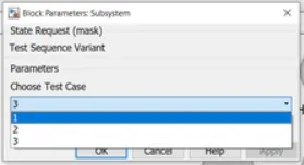
Test:1
Select 1 variant in the Test sequence variant block.
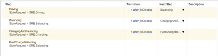
There are three stages of driving conditions:
1. Driving for 3000 seconds
2. Balancing for 1000 seconds
3. Charging and balancing for 5000 seconds
4. After that post-charge balancing operation occurs till the end of the simulation period.
Simulation results:
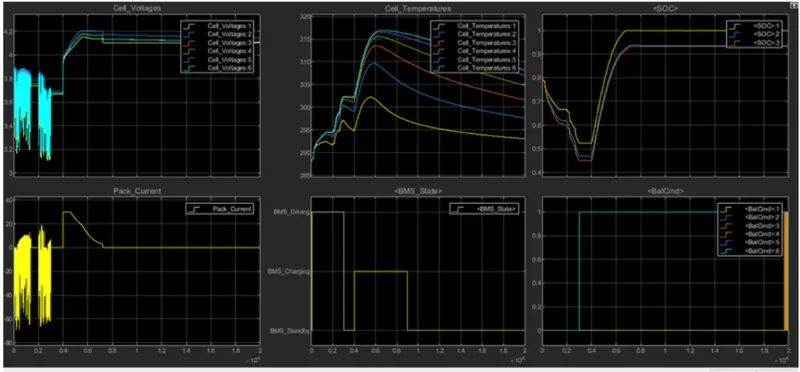
0-3000 seconds:
Initially, the battery pack is in 80% charged condition and for the first 3000 seconds is the driving mode so the battery is in discharging condition.
The temperature of the cells is increasing gradually in driving conditions and the pack voltage initially at 3.8V and start decreasing to 3.1V. Voltage varies from 3.1V to max of 3.9V. The SOC of battery reduced to 30%.
Temperature of cell 1 is lesser and temperature of cell 6 is higher than all other cell.
3000-4000 seconds:
After 3000 seconds, balancing stage starts,
Voltage variation occured in driving mode is balanced in this stage. From 3000-4000 second cell balancing occurs, batery module voltage is balanced to nearly 3.7V.
4000-9000 seconds:
After 4000 seconds, charging occurs cell voltage raises from 3.7V to 4V. Initially the battery is in constant current charging mode till it reaches 4.2V and pack current increased from 0A to 30A (4000-7000 sec). Temperature of cells are also increased exponentially. Cell 1 raised to 302K and other celss raised to 317K. After that constant voltage charging occurs(7000-9000 seconds) full capacity is reached then pack current reduces to zero. Temperature of cells reduced after 9000 seconds and remains stable at reaching ambient temperature.
SOC is initially at 30% during start of charge stage now it increased to 100%.
SOC Estimation graph:
Battery initial SOC is 80%. Yellow plot represents coulomb counting method and it shows SOC 45% after 3000seconds(driving cycle) at end of 9000 seconds showing 100%SOC.
Blue represents Unscented kalman filter method, it shows the SOC 30% after 3000seconds(driving cycle) at end of 9000 seconds showing 93%SOC.
Red represents Extended kalman filter technique, , it shows the SOC 30% after 3000seconds(driving cycle) at end of 9000 seconds showing 93%SOC.
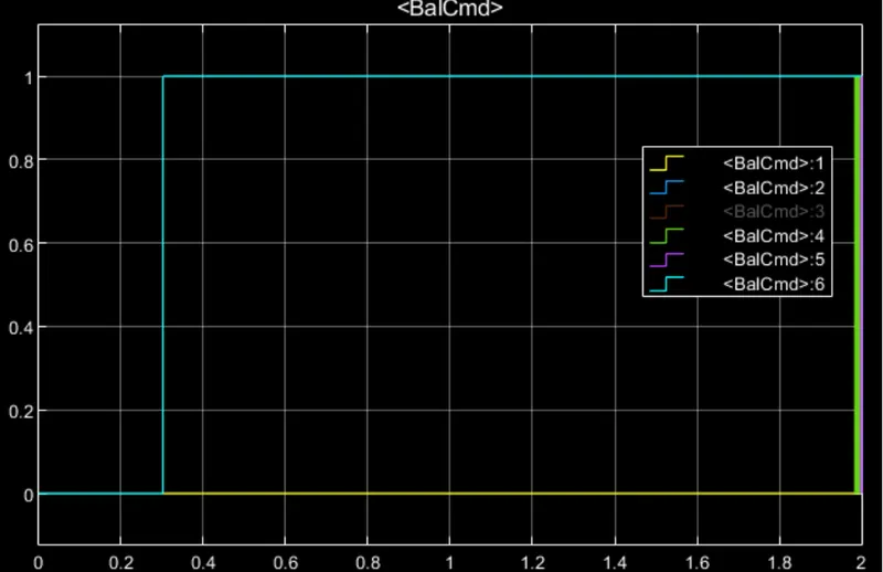
Cell balancing:
After 3000 seconds cell balancing starts, cell 2 and cell 6 raised to level 1 its voltage is higher than other cell voltage. Cell 1 is having lower voltage throughout the simulation. At end of simulation all cell voltages try to balance equally.
Test case:2
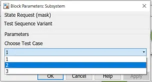
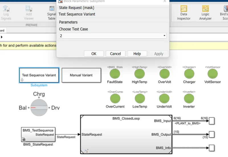
Select test case 2 in test sequence variant dialog box and in BMS test sequence state request case 2 is selected. This test case has two modes
1. Driving 1-5000seconds
2. Charging
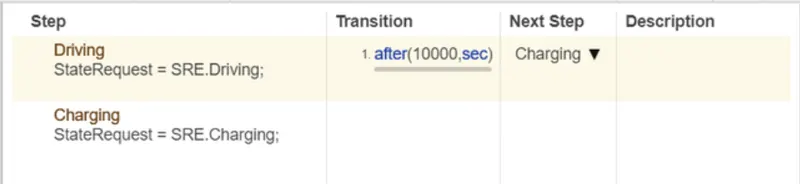
In this mode there is no cell balancing stage
Simulation results:
Dashboard results there is no fault indication.
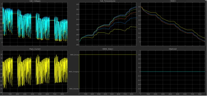
Initially the soc is in 80% and voltage is 4V. During driving mode the voltage varies from max of 3.9V to 3.05V. The battery capacity drained to 0% at end of 9000seconds. Standby mode condition is inbetween the driving mode. After that the battery packs starts charging.
Temperature of cell 1 lower than other cell. The cell temperatures are reducing slightly inbetween the stand by modes. Temperature of cell
SOC plot:
Coulomb counting SOC plot shows the remaining capacity as 0% and the Unscented kalman filter method shows remaining capacity as 0% and Extended kalman filter method shows remaining capacity as 0% at end of driving mode.
Cell balancing:
For this test case there is no cell balancing.
The driving stage is for 10000 seconds but the battery capacity drained to 0% at the end of 9000seconds. so the charging only occures after 10000seconds. Till that diving stage continues.
Test case:3
Select test case 3 in test sequence variant box and in BMS test sequence state request box. This mode has only charging mode for entire time duration.
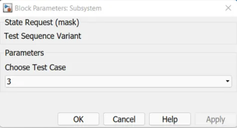
Simulation results:
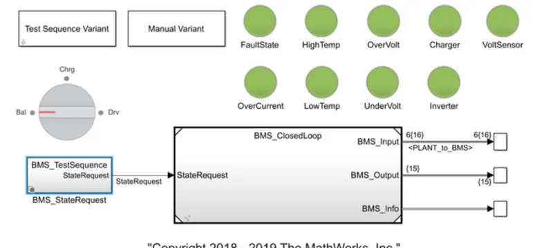
There is no error occured, indication lamps are in green color.
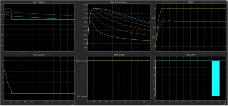
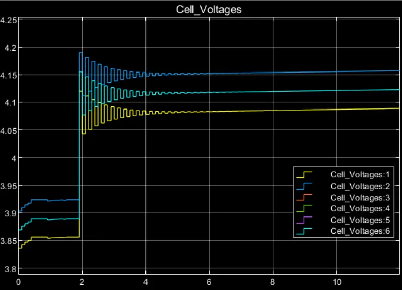
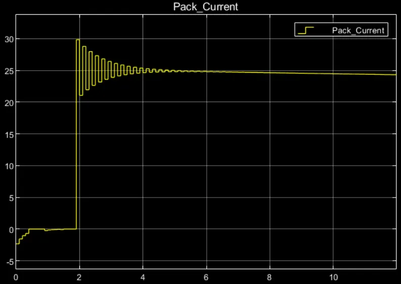
Initially the battery pack charge in constant current mode the cell current increases from 0 to 30A and the cell voltage increases to 4.2V.
After that contant voltage charging occurs, the cell current decreases from 30A to 0A at the end fully charged state.
SOC plot:
Initially the battery pack soc is 80%.
SOC estimation using coulomb counting method shows 100%, SOC estimation using Unscented kalman filter method shows final capacity as 93% and Extended kalman filter method shows remaining capacity as 93%.
Cell temperature:
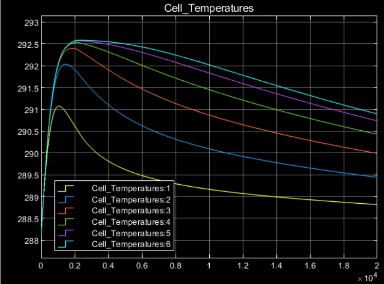
The cell temperatures increases during charging condition, cell 6 has highee temperature than other cells.
After full charge the cell temperature starts to reduce to ambient temperatue.
Cell balancing:
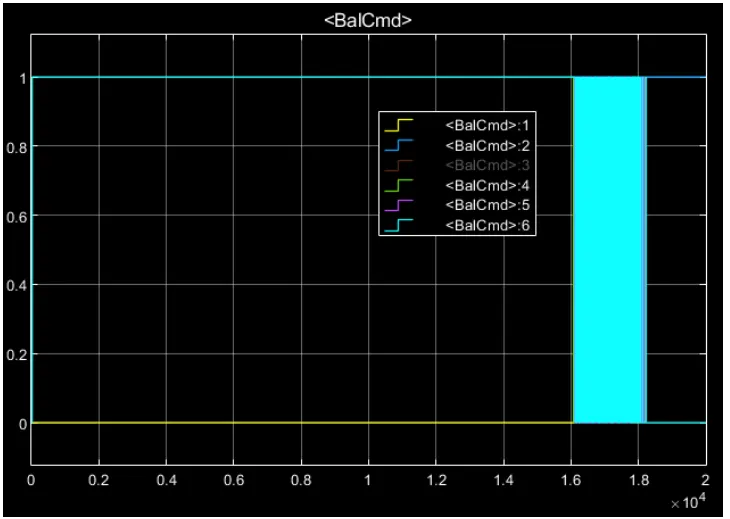
Cell balancing is in process since the beginning, cell 6 and cell 2 starts to balance with respect to cell 1 and other cells balancing at end of simulation.
B)
Coulomb counting:
Coulomb counting is a method to to calculate the amount of energy remaining inside the battery.
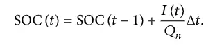
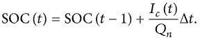
It is done by integrating the discharging/charging current I(t) over time to estimate SOC.
SOC is defined as the rate of capacity available to the total capacity at fully charged condition. SOC is in the range between 0 and 1.
SOC can be estimated from discharging current I(t) with previouslt estimated SOC values SOC(t-1).
Modified coulomb counting:
Modified Coulomb counting method uses the corrected current to improve the accuracy of estimation.
The corrected current is the function of discharging current. There is a quadratic relationship between the corrected current and discharging current of battery. Corrected current is calculated by the following form:

K0,K1,K2 are constant values obtained from the practice experimental data.
Modified Coulomb counting method, SOC is calculated by the following equation:
BMS Coulomb counting for SOC Estimation:
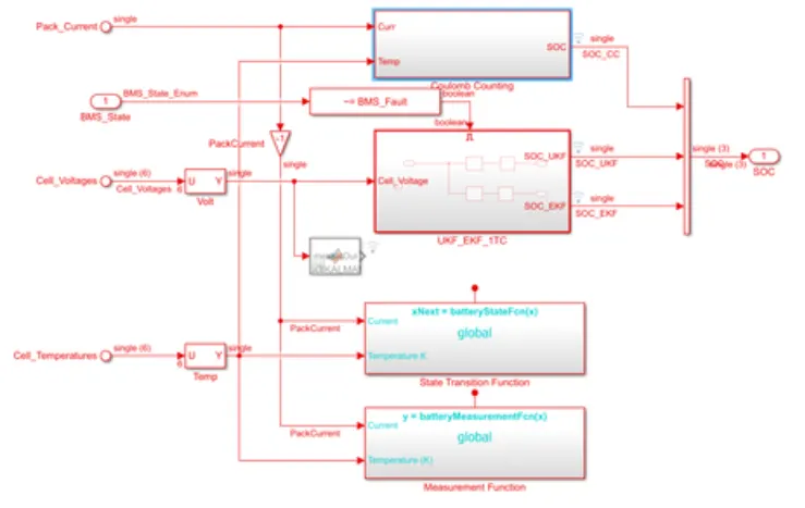
Inside BMS model a subsytem called SOC_Estimation. Inside SOC_Estimation block three SOC estimation blocks are there.
Coulomb counting method, Unscented kalman filter method, Extended kalman filter method.
Inside coulomb counting method several blocks are there used to estimate the SOC.
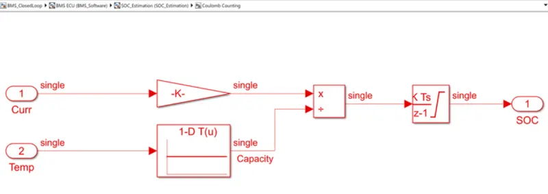
Input block, Gain block, Multiplication block, Integration block, Lookup table block.
Inputs are the discharge current(A) and temperature value.
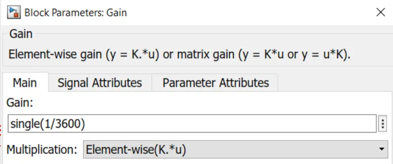
Gain Block:
Discharge current is changed terms of Amp-hour by multiplying with 1/3600 using gain block.
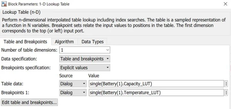
1-D Lookup table:
1-D look up table consist of temperature and capacity data. The input temperature value matches with the lookup table and capacity value is taken.
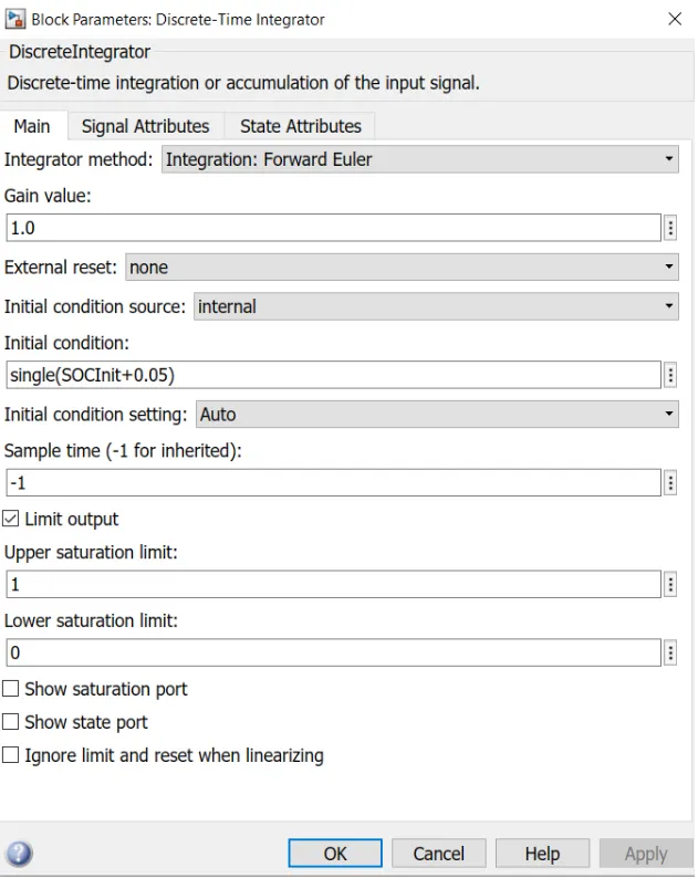
Integrator block:
saturation limit are from 0 and 1.
Working:
Discharge current is changed terms of Amp-hour by multiplying with 1/3600 using gain block. The value is divided by the capacity due to temperature change. Then using integrator block the values integrated over time. saturation limit are from 0 and 1. The SOC value is between 0 and 1 and interms of percentage 0 and 100%.
Reference:
2. https://in.mathworks.com/support/search.html/videos/verifying-validating-and-testing-battery-management-systems-part-2-managing-requirements-for-battery-management-systems-bms-in-simulink-1584342315317.html?fq[]=asset_type_name:video&fq[]=category:simulink/index&page=1