Week 7 State of charge estimation
1.Simulate the 3 test cases from harness dashboard and write a detailed report on the results :
Simulink model :
- The model is taken from Mathworks website.
- In this model it shows the Design and Testing of lithium ion battery management algorithms .
- This example project is used as a reference to get started with Design of battery management system with MATLAB and Simulink.
Algorithm used in these system are as follow :
- state of charge estimation using extended Kalman filter , unscented Kalman filter.
- Passive battery cell balancing.
- State machine for pre-charging and contactor management.
- Fault management like Over and under voltage ,Over current over temperature etc.
- Charge and discharge current limit calculations.
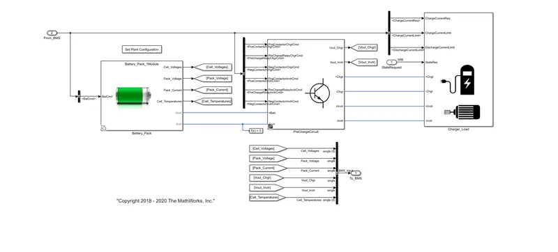
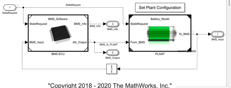
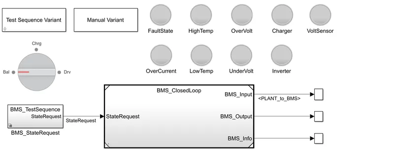
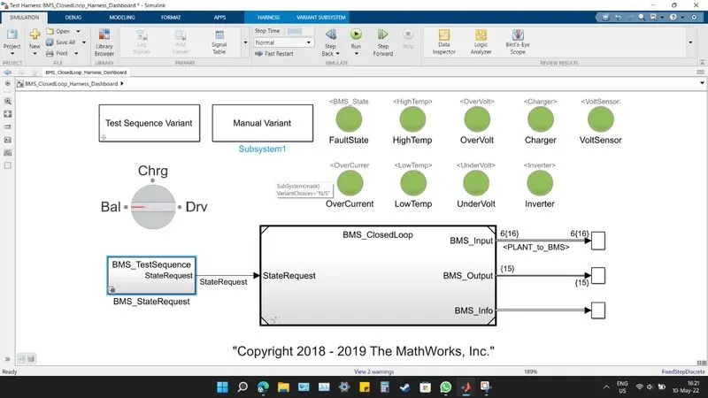
- Below is the picture of the dashboard .
Case 1 :
- In test sequence variant , first we select 1 option .
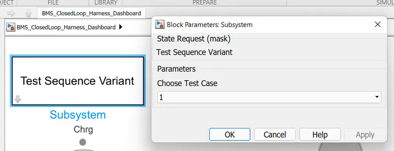
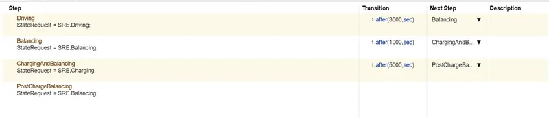
- In case 1 we can see that balancing is done for 3000 sec.
- Then for 1000 sec charging and balancing .
- For next 5000 sec postcharing and balancing .
- In dashboard we can see that green light is shown for all parameter after doing siulation which means that there is no error or overheating in system.
- It generally give the output of the system.
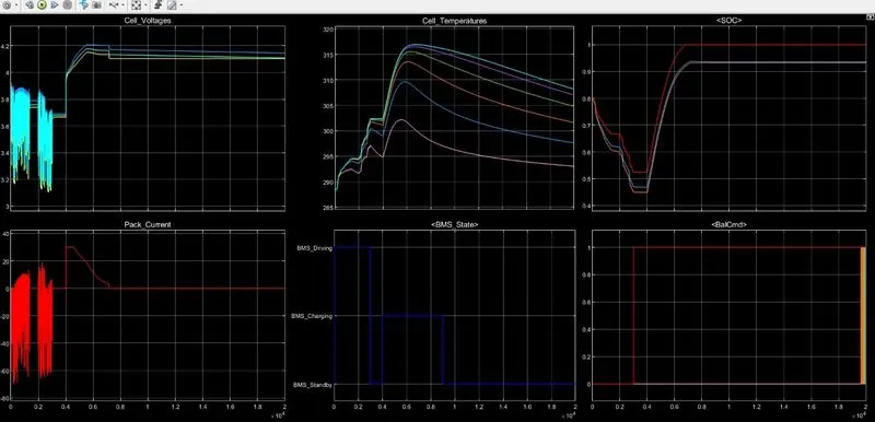
Outputs :
cell voltage : its generally varies between 3.1 and 4.2 v.
cell temperature : initially it is 287 k then it increases upto 318 k and then it decreases .
SOC : initially it is at 0.8 than it decrease and increases to 1.
pack current : its maximum values goes to 25 and and become zero and remains constant .
BMC state : first it is in driving mode than it is in charging mode and then it is in standby mode.
Balcmd : first its value is zero than it become 1 and remain constant .
2 ) case 2 :
- In this case we have selected second option from dropdown menu in choose test case .
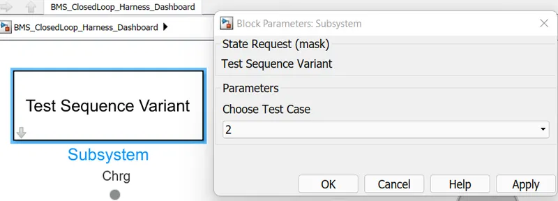
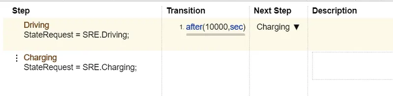
- In this case there is two mode ,one is driving and second case is charging .
- In this case charging is done for 1000 sec .
- Is is in driving mode then it shift to charging mode .
Outpts :
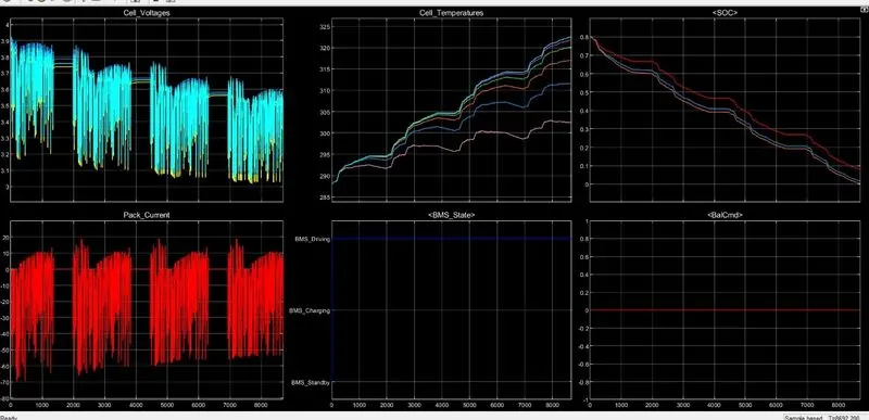
From the graph it can be seen that :
- cell voltage : it varies from 3 to 3.9 v .
- cell temperature : it increases from 285 k to 320 k.
- SOC : it dcrease from 0.8 to fully discharge .
- PAck current : it is fluctuating between -80 to 20 A .
- BMS mode : it states that it is in driving mode .
- Balcmd : it is zero and constant .
Case 3 :
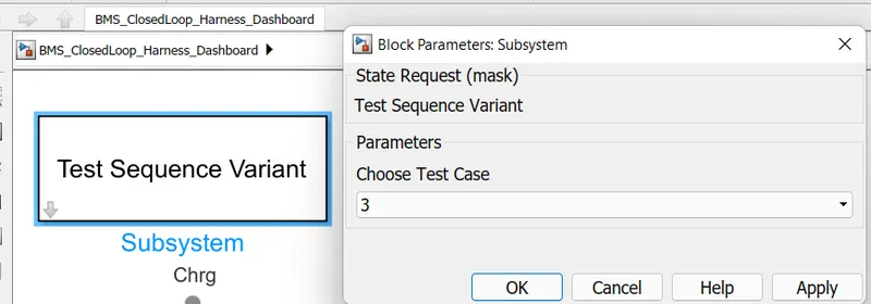
- Now chose test case 3 from drop down menu in test sequence variant :
- In this case the only charging is done .

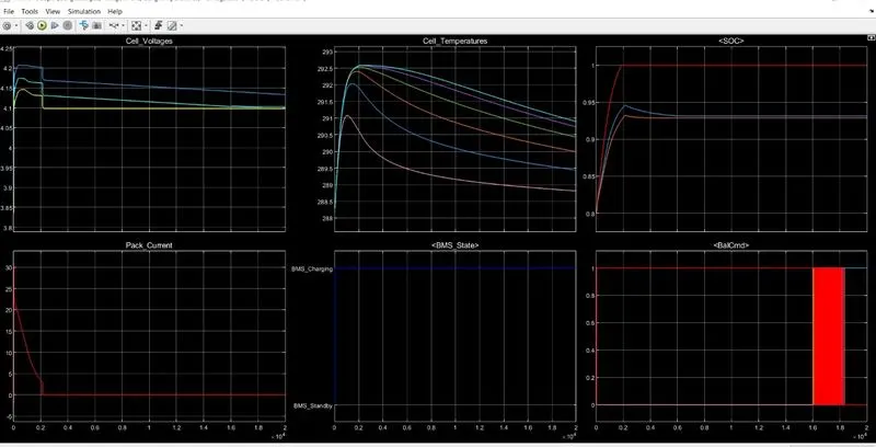
Outputs :
- Cell voltage : initially it increases and become constant at 4.2 v.
- Cell temperature : initially temperature increases for short time and decrease for long period of time .
- SOC : it increases from 0.8 for sorter time to 1 and remain constant for that value .
- peak current : current decreases from 0.8 to 1 A .
- BMS status : it shows thw charging mode .
- BAl cmd : its value is constant and remain 1 .
2.What is coulomb counting? Refer to the above model and explain how BMS implements coulomb counting for SOC estimation ?
- coulomb counting is a technique used to track the state of charge of a battery pack .
- It works by integrating the active flowing current over time to derive the total summof energy entering or leaving the battery pack .
- This produce a capacity that is typically measured in amp-hours.
- The columb counting technique measures the dicharging current of a battery and integrates the discharging current over time in order to estimate SOC .
- Columb counting method is done to estimate the discharging current , and previously estimated SOC values .
- Integrating the current into or out of a battery gives the relative vslue of its charge .
- Coulomb counting needs a starting point . If the initial charge in the battery is known , from then on coulomb counting can be used to calculate the charge.
equation is given by :
`SOC (t) = SOC (t-1) * int(It *n /(Qn))*dt`
where SOC (t-1) = SOC at previous time step
n = efficiency
t = current time step
t-1 = previous time step
Q = charge capacity of the battery .
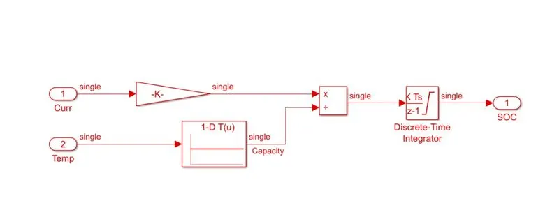
- This method is accurate and reliable than the voltage translational method but does not take into account the discharge rete , temperature , hysteresis , age of the battery , etc .
- In Bms for SOC estimation , it takes value from ambient temperature and current and integrate the value to give current .
- The soc of the battery , which is used to describe its remaining capacity , is a vey important parameter for a control strategy .
- By quantiying the charge delivered by the battery through sensing its input and output current if the DOD estimated through coulomb counting is uncalibrated it is not equal to the actual DOD,eventually , the battery will be charged or discharged so far that voltage translation can be used to estimate SOC and , knowing the capacity can be translated to DOD , the estimated DOD can be calculated .
References :
https://skill-lync.com/knowledgebase/simulation-of-bms-model-in-simulink