Week 7 State of charge estimation
State of charge estimation
Lithium-ion battery packs are widely used energy storage systems in electric vehicles. The battery management system (BMS) is responsible for safe operation, performance, and battery life under diverse charge-discharge and environmental conditions. When designing a BMS the cell voltage and temperature, state of charge, state of health, and the charging profile have to be controlled and maintained.
Also, it indicates whether there has been a fault, for example, that any cell has reached an over-temperature condition or under-voltage condition (Under-voltage occurs when the average voltage of a system drops below intended levels. It is usually caused by undersized or overloaded utility).
This article will help you to get an insight of the BMS model and it also discusses the various subsystems used here. We will also see how the fault parameters can be indicated with the help of the BMS closed loop using SIMULINK.
Download the closed-loop BMS using the below link:
The steps to simulate and plot the various parameters will be discussed step by step:
1. Download the model using the above link. This will provide a battery system zip file.
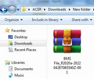
2. Extract the zipped files.
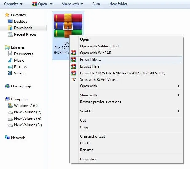
3. Open MATLAB-SIMULINK. Click on Open and select the BMS closed-loop model.
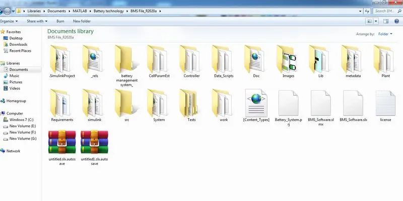
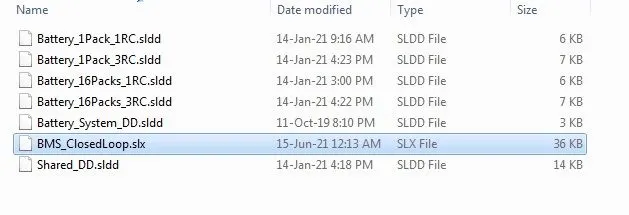
4. From the above shown extracted image, select System--> BMS close loop
BMS Closed Loop:
A battery management system (BMS) is an electronic control circuit that monitors and regulates the charging and discharging of batteries. The battery characteristics to be monitored include the detection of battery type, voltages, temperature, capacity, state of charge, power consumption, remaining operating time, charging cycles, and some more characteristics. The task of the battery management system is to ensure the optimal use of the energy present in a battery. In order to avoid loading the batteries, the BMS system protects the batteries from deep discharging, from over-voltage, which are results of extreme fast charging and extremely high discharge current. In the case of multi-cell batteries, the battery management system also provides for a cell balancing function, to manage that different battery cells have the same charging and discharging requirements.
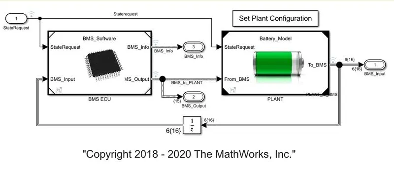
The model studied is a BMS Simulink model by Mathworks and is shown above.
The BMS model is a combination of various subsystems. The model consists of 3 parts, the BMS ECU, BMS plant and the dashboard.
BMS ECU:
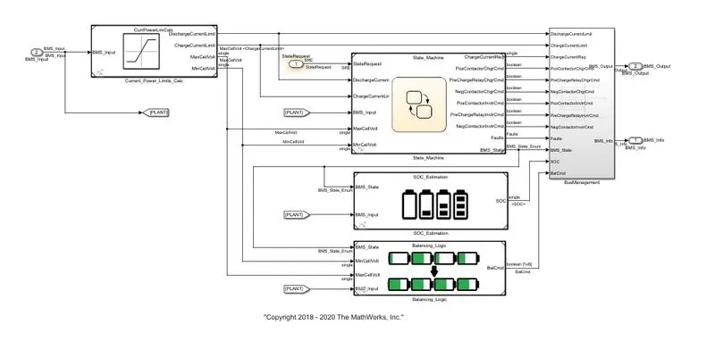
It is the brain of the BMS which calculates the charging and discharging current, the state of charge (SOC), cell balancing, and the state machine which provides the control logic. The calculated values are passed through a bus which is then relayed to the BMS plant.
BMS State Machine:
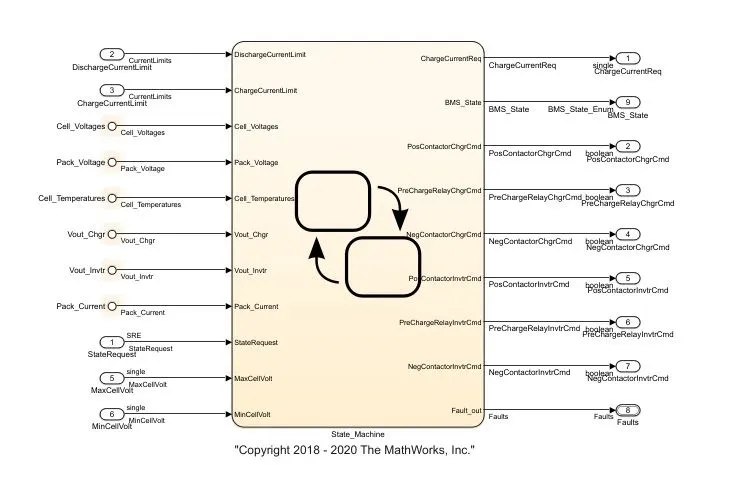
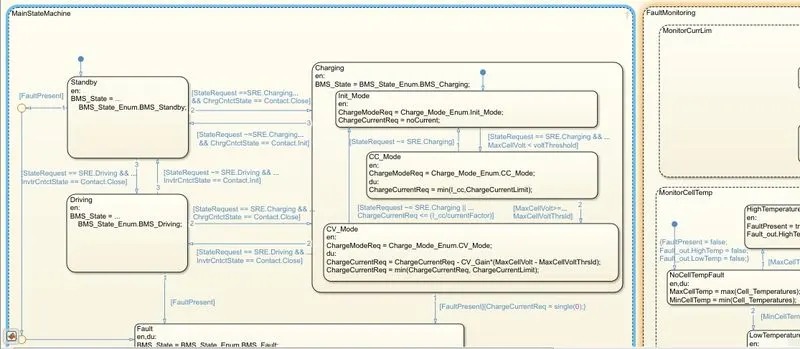
This sub-system is the control logic of the BMS ECU. It consists of a flow chart that calculates the current and voltage during the different operating conditions being driving, charging, and balancing. The flow chart of the state machine is given below.
BMS PLANT:
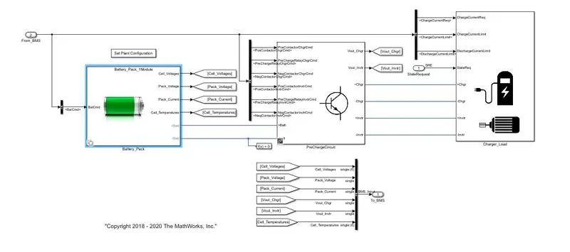 This subsystem is the actuator of the BMS. The battery pack subsystem is a combination of battery modules. There are two options, 1 module or 16 modules. 1 module is selected by default and it has 6 cells. The module subsystem provides details of parameters like cell voltage, cell temperature, pack voltage, and pack current. The second subsystem is the current charging circuit which is activated during the charging operation. The output system is called charger_load where the battery charger and motor drive are the outputs and depending on driving or charging conditions the required subsystem is selected.
BMS Harness Dashboard:
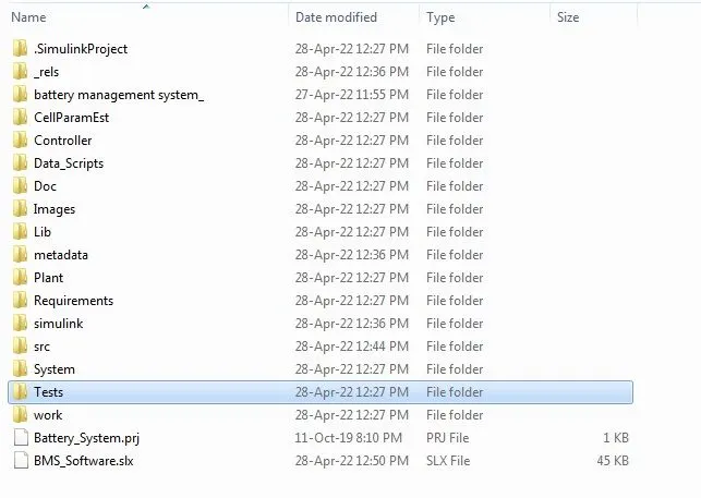


From the above shown picture, Select Tests-->System-->BMS_Closedloop_Harness
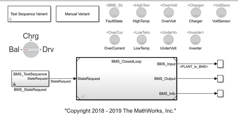
It is the model that controls the input parameters of the BMS system. There are 3 operation conditions which are driving, charging, and balancing. The LED lights are used to represent the output conditions where they turn green if all systems are good and turn red if there is a fault. The test sequence variant block has 3 test conditions. The BMS model is simulated according to these 3 cases.
Output:
Test Condition 1 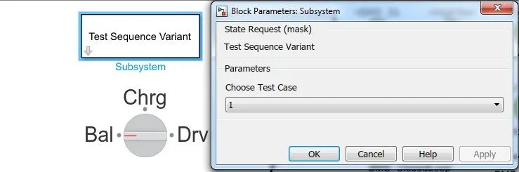
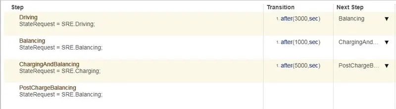
The simulation is run for 20000 seconds. For 3000 seconds the vehicle is in driving condition, from 3001 to 4000 seconds the BMS engages the balancing condition and finally, from 4001 to 9000 seconds the BMS charges the battery and starts balancing again from 9001 to 20000 seconds. The dashboard ais given below.
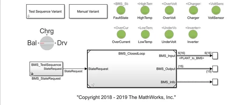
The LED lights indicate that there are no issues and the simulation ran without fault.
Test Condition 2:
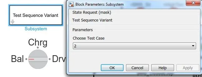

In the second test condition, there is only the driving and charging phase where for the 10000s the vehicle is in the driving phase, and from 10001 to 20000s the vehicle is in the charging phase. The dashboard is shown below.
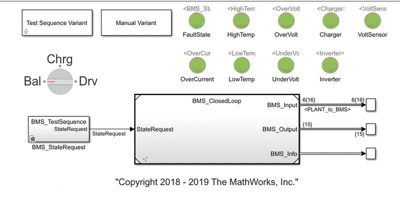
The simulation is run successfully without any faults as shown by the LED lights.
Test Condition 3:
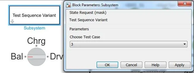

This condition is only to study the cell balancing during the simulation. The dashboard is shown below.
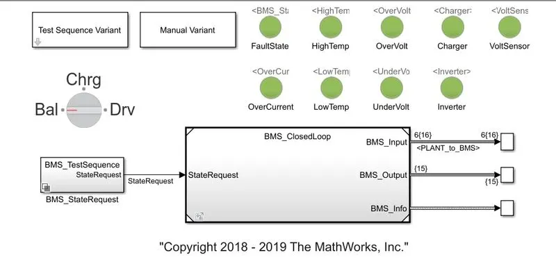
Scope Results:
Test Condition 1:
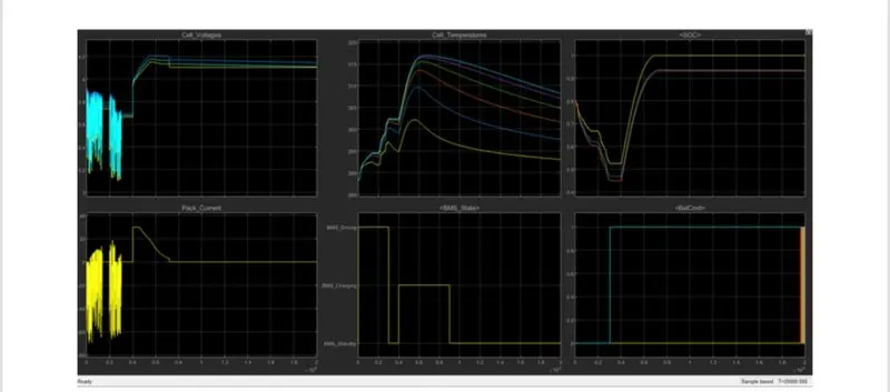
The graphs plotted are cell voltages, pack current, cell temperature, state of charge, BMS state, and balance command. The voltage and current plots show the variation during the 3 conditions while driving the current and voltage fluctuates according to the motor load and remains constant during balancing. During the charging phase, the current and voltage increase and then stabilizes during the balancing phase. The cell temperature rises during the charging and discharging phases and reduces during the balancing phase. The state of charge decreases during the driving phase increases during the charging phase and remains constant during the balancing phase. Here 2 cells are combined to produce one plotline and hence there are only 3 plots for the state of charge.
Test Condition 2:
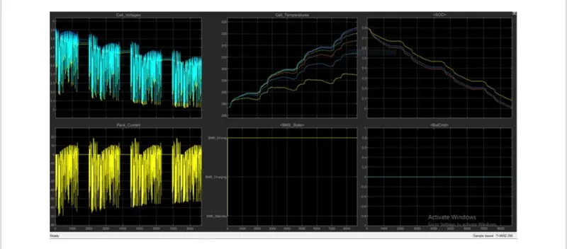
The above graph represents the results of test condition 2. The current and voltage fluctuations indicate the driving phase and the increase in the current and voltages after the fluctuations indicate the charging phase. The cell temperatures increase during the driving and charging phases and the state of charge decreases during the two phases.
Test Condition 3:
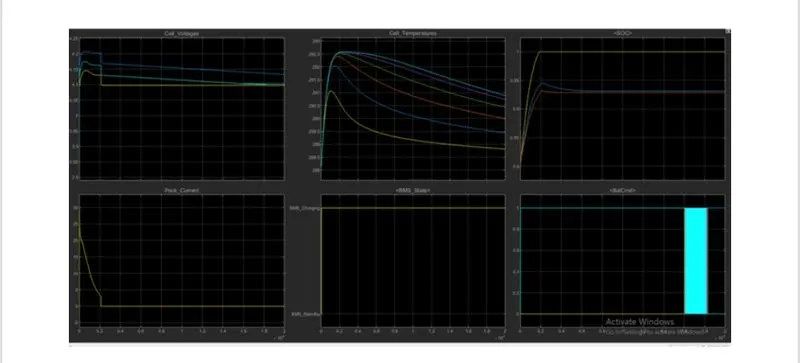
The simulation is successfully run without faults. The current and voltage values decrease when the BMS is balancing the cells. The temperature also reduces in this phase and the state of charge increases to 100% and continues to remain at 100% for the remainder of the duration.
2. WHAT IS COULOMB COUNTING? HOW IS IT USED TO DETERMINE THE ESTIMATION OF SOC:
State of Charge (SOC) is a fundamental concept to understand the use of batteries, which is used to describe the remaining capacity in a battery. As the SOC is an important parameter that reflects the battery performance, accurate estimation of the SOC can not only protect the battery, prevent over-discharge, and improve the battery life but also allow the application to make rational control strategies to save energy. SOC is defined as the ratio of the current capacity of a battery to its normal capacity and represents the maximum amount of charge that can be stored. The equation of SOC is,
SOC(t)=Qt/Qn
Where,
Qt Current capacity.
Qn = Nominal capacity.
The Coulomb counting method measures the discharging current of a battery and integrates the discharging current over time in order to estimate SOC. Coulomb counting method is done to estimate the SOC which is estimated from the discharging current, and previously estimated SOC values. The equation to calculate the SOC using Coulomb Counting is given as,

Where,
soc(t-1) = Previous SOC value.
It = Discharge current.
The sub-system that calculates the state of charge in the BMS model is given below,
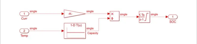
The system uses current and temperature as the inputs where the current is passed through a 1D look-up table. The current and temperature are then divided and integrated to obtain the state of charge.
CONCLUSION:
• The Battery Management System Model by Simulink is simulated and the output is studied based on the given test conditions.
• Coulomb Counting method to estimate the state of charge is explained along with the simulink model in the BMS system.