Week 7 State of charge estimation
1.Simulate the 3 test cases from harness dashboard and write a detailed report on the results.
A: Download the zip file from the given link:
- Extract the file and copy it to the matlab folder.
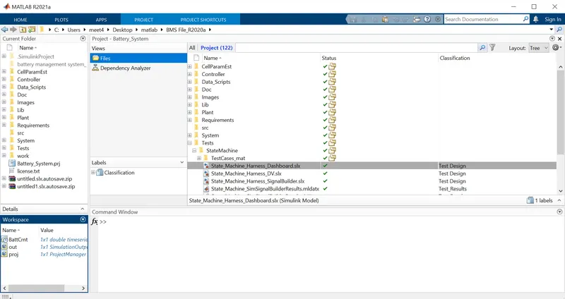
- Open Matlab, change the current folder path.
- Open the extracted model in new file.
- From project- shortcuts choose BMS closed loop harness dashboard model file.
- Under Tests---> System--->BMS_Closedloop_Harness_Dashboard model file.
- Select open project and model in pop-up dialog box
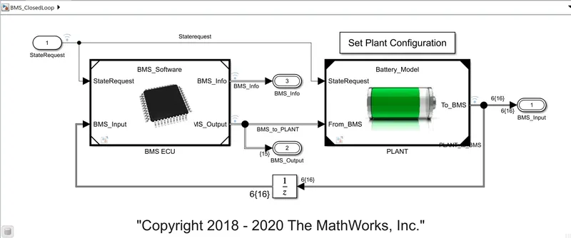
BMS Closedloop model:
The BMS Closedloop main model is given below. It consists of two subsystems, BMS ECU and PLANT. Select set plant configuration , inside it there are battery pack unit, pre charge unit or load units. Inside battery pack unit there are 2 type of configurations as 1 module with 6 cells and 16 modules with 96 cells, select 1 module from the subsystem.
Test sequence 1:
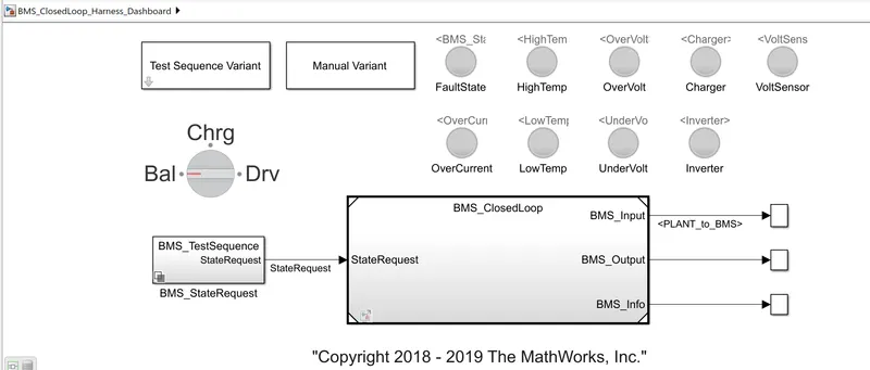
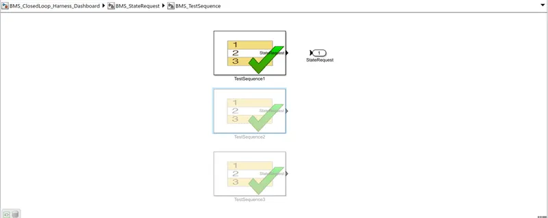
Select 1 from test sequence variant block and click on apply.
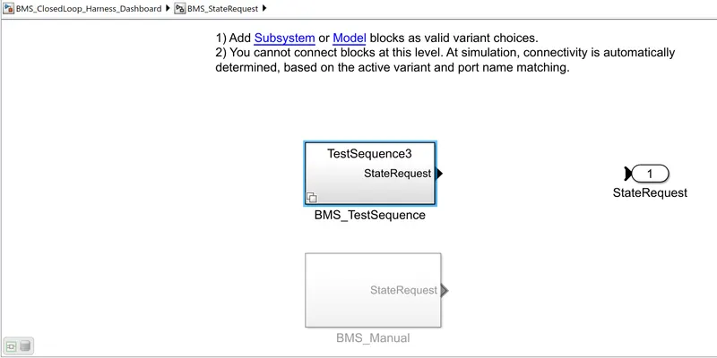
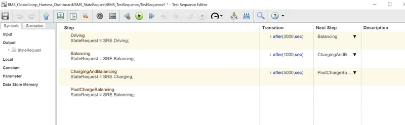
Sequence operations for test sequence 1: From the editor block it is given as for driving it is given as 3000 sec, after 3000s comes the balancing and it is given for next 1000sec, then after that comes the charging and balancing for the next 5000 sec and finally the post charge balancing operation comes till the end of the simulation period.
Result:
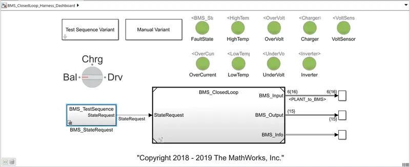
After running the simulation all the lamps will be in green colour indicating that there is no fault in the simulation.
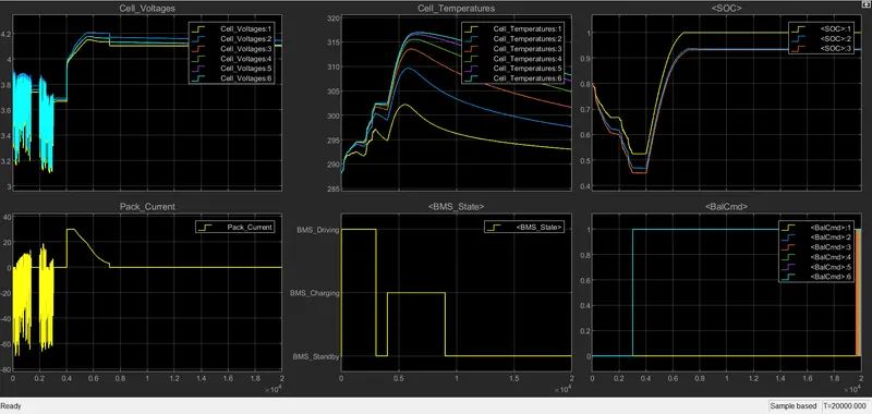
Output plots are given above whch indicates the cell voltages, cell temperature, SOC, pack current, BMS state, balancing command. It is understood that till 3000 sec it is in driving state and then starts balancing and the after 1000sec charging begins.
Test sequence 2: Select 2 from test sequence variant block and click on apply.
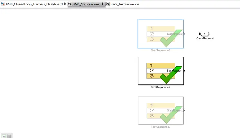
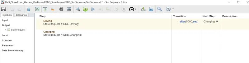
Sequence operations for test sequence 2: From the editor block it is given as for driving it is given as 5000 sec, after 5000s comes the charging till the end of the simulation period.
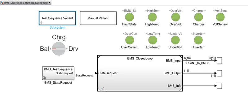
Results: All lamps are green indicating no fault.
Waveforms obtained:
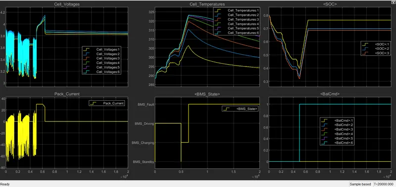
Since driving time is set as 5000 sec it can understood from the detailed view of graph obtained. After 5000sec charging begins to takes place.
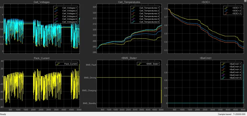
Here balancing is not done because balance states are in 0 for entire drive mode. SOC reduced from 80% to 0% in the entire drive mode.
Test sequence 3: Select 3 from test sequence variant block and click on apply.
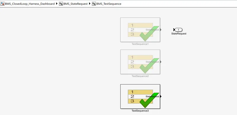
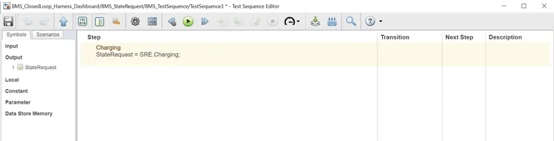
Results: All lamps are green indicating no faults.
Waveforms obtained:
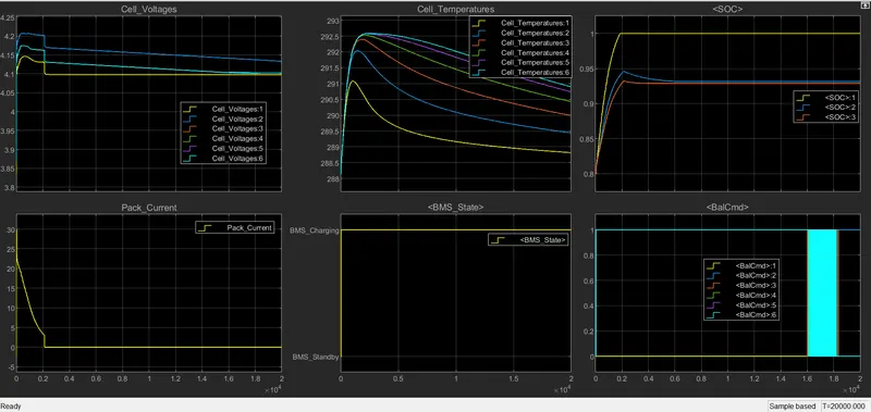
Here as seen from the graph the entire battery pack sequence is operating in charging mode. In case of SOC gets fully charged at 2000sec and is remaining at full charge for rest of the sequence. In case of cell balancing from 0sec to cell 2 and 6 start balancing w.r.t. cell1.
Conclusion:
The 3 test cases from harness dashboard are simulated and its output waveforms are discussed and analysed.
2.What is coulomb counting? Refer to the above model and explain how BMS implements coulomb counting for SOC estimation ?
A: The state of charge is defined as the ratio of the available capacity Q(t) and the maximum possible charge that can be stored in a battery. A fully charged battery has SOC 1 or 100% while a fully discharged battery has an SOC of 0 or 0%.
The Coulomb counting method is one of the most general and simple methods of estimating the SOC. We use it for a baseline comparison for more advanced methods. The Coulomb counting method measures the current of the battery and integrates the current over time to estimate SOC.
- It defines rate of flow of current inside and out of the battery.
- Capacity of battery.
SOC(t)= SOC(0)+ 1/Cn ∫ni*i(t)dt
where SOC(t) is the current value, SOC(0) is the previous value, dt represents the timeand for + or addition symbol it indicates the charging and if it is - or minus it indicates the discharging.
SOC calculation in BMS model:
Inside the BMS model click the subsystem BMS ECU and again the SOC estimation. Inside SOC estimation click on Coulomb counting subsysem. Each stage is shown in figures below.
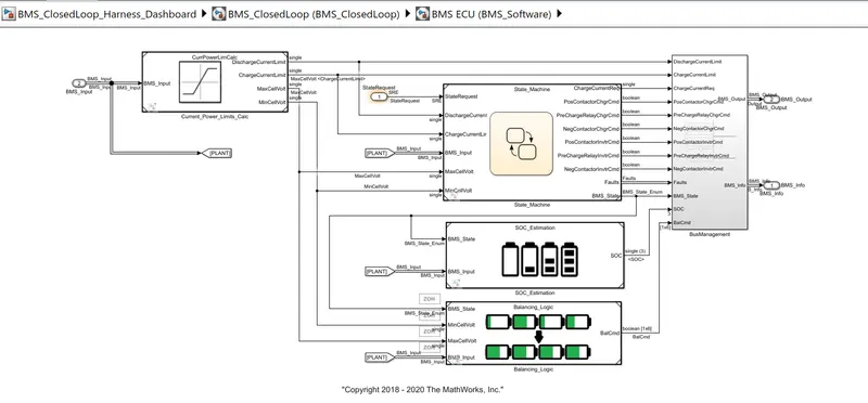
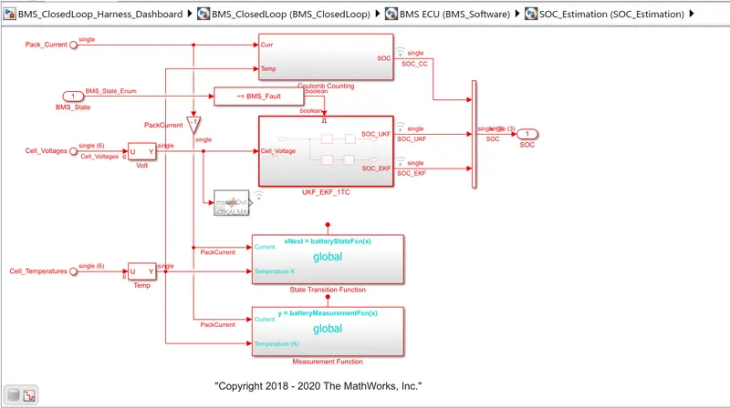
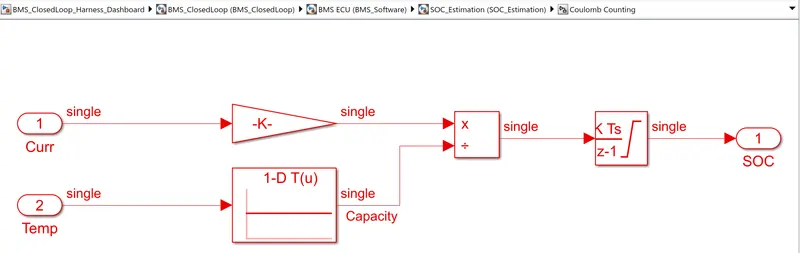
Inside coulomb counting subsystem there are gain block, lookup table, discrete intergrator, divide block. The parameters are all kept default and is shown below.
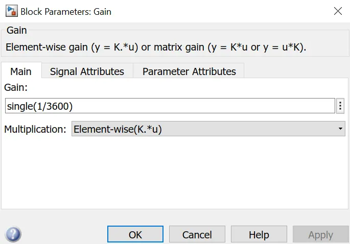
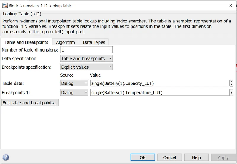
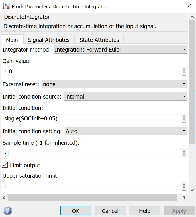
Here the discharge current from battery is given to gain with value 1/3600 to convert current to Ahr. This value is again divided then integrated with a gain value of 1 with sample time -1 as in the discrete integrator block. Saturation limits are from 0 to 1. This is the procedure to calculate SOC using Coulomb counting method.