Project
AIM
To carry out system level simulation of an All Terrain Vehicle using simulink.
OBJECTIVE
To learn about the working of all terrain vehicles and to prepare a technical report on BAJA ATV Model.
DESCRIPTION
Literature Study:
- BAJA SAE : BAJA SAE is an engineering design competition for undergraduates and graduate engineering students. Here the students will design and develop their own ATV considering design constraints and safety.
- ATV: All Terrain Vehicle is defined as a motorized off-highway vehicle which travels on low pressure tires, with a seat straddled by the operator, along with handlebars for steering control. It is designed to run on soil, gravel, mud pebbles etc. They offer high performance riding and are applicable in industries like sports, military, entertainment etc.
- CVT: It stands for continuosly variable transmission where it has one gear that is variable for all driving conditions. Iuses two pulleys connected with a belt between them. It automatically varies the transmission gear ratio and has better fuel economy.
Major Parts:
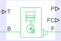
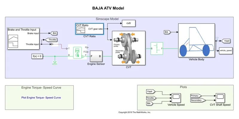
- Generic Engine: It is an internal combustion engine which is suitable for spark ignition and diesal engines. Provides speed-torque and speed-power parameters. T, Throttle is the input provided which determines the torque of engine. B represents the engine block, F represents engine crankshaft. P gives the output power in watts and FC is the fuel consumption.
- Engine sensor: It is an ideal mechanical rotational motion sensor. Here R and C are the mechanical ports and W and are physical signal output port for velocity and and displacement.
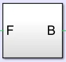
- Simple Gear: It consists of a driver gear B and a driven gear F. These are mechanical rotational conserving ports.
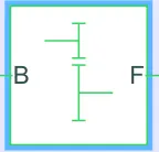
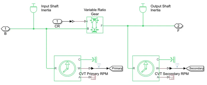
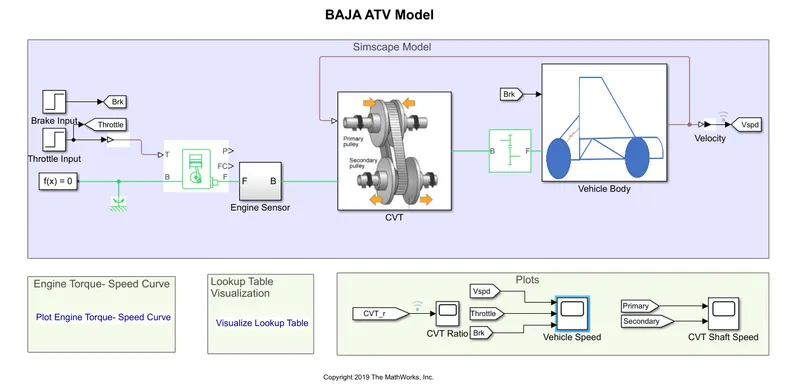
- CVT Subsystem: The continuosly variable transmission subsystem consists of inertia block, variable ratio tranmission gear, variable diameter pulley system. Here one is driver pulley or input pulley which is connected to crankshaft and energy from engine enters the transmission frome here. Other driven pulley or output pulley gets energy from first pulley and transfers it to the driveshaft.
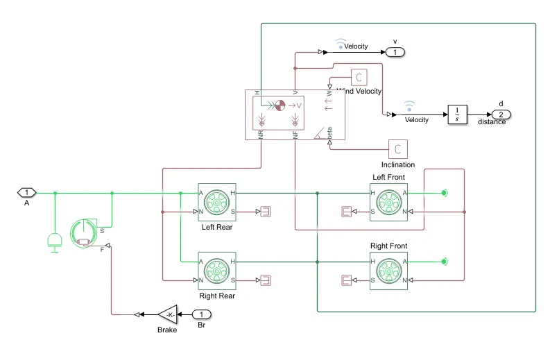
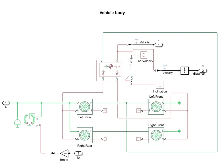
- Vehicle body Subsystem: It consists of the following blocks; vehicle body, tire, double shoe brake.
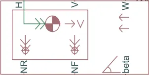
- Vehicle body - It represents a two-axle vehicle body in longitudinal motion that is front axle and rear axle. The constraints under consideration are body mass, drag force, road inclination, road profile etc. The vehicle can have same or different number of wheels on each axle. NR - rear axle normal force N NF - front axle normal force N Beta - road inclination angle rad V - longitudinal velocity m/s W - head wind speed m/s H - horizontal motion
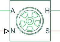
- Tire - Vehicle body is connected with 4 tires each per axle to move the vehicle according to the power input to the axle. Where A is the axle, H is mechanical translational port, S is tire slip and N is normal force.
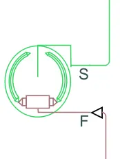
- Double Shoe Brake - It represents frictional brake with two pivoted rigid shoes that press against a rotating drum to produce a braking action. The right shoe sits inside or outside the rotating drum in diametrically opposed configuration. A positive actuating force causes the rigid shoes to press against the rotating drum. Viscous and contact friction force between the drum and the rigid shoes cause the rotating drum to deccelerate.
Blocks used for simulation:
- Signal builder
- Generic engine
- Engine sensor
- Vehicle body
- Simple gear
- Tire
- Variable gear ratio
- Inertia
- Double shoe brake
- Rotational motion sensor
- Simulink to PS converter
- Lookup table
- Mechanical Reference
- Scope
- Display
Simulation categories:
- BAJA ATV without lookup table (with and without dashboard)
- BAJA ATV with lookup table (with and without dashboard)
1.1 BAJA ATV without dashboard
INPUT:
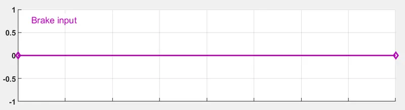
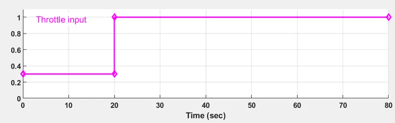
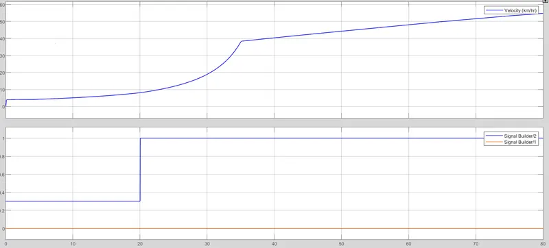
Here input provided are brake and throttle where brake applied is zero and throttle signal which is obtained using a signal builder varies from 0.3 to 1 as shown in the graph. Throttle signal is the exact opposite of a brake were it provides the necessary acceleration for the vehicle.
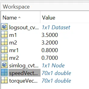
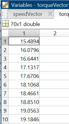
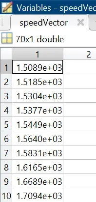
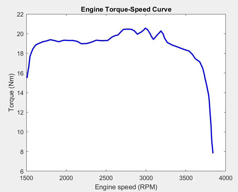
Torque and speed vectors taken from workspace are shown below;
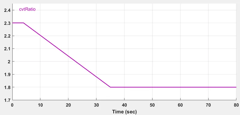
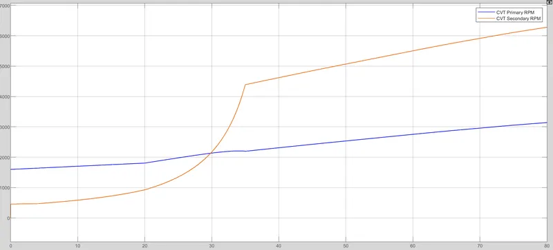
The engine generates output rpm which is given to crankshaft output and is sensed using rotational sensor which is then given to the gear mechanism and the output speed from there is given to the cvt block. CVT ratio is also provided to the CVT block using a signal builder block;
OUTPUT:
*Torque-Speed curve is illustrated below; it is provided from Matlab workspace window to generic engine block to generate the output RPM. It is a constant input for all cases.
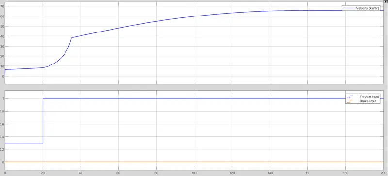
*Velocity plot along with input brake and throttle: Since the brake applied here is zero the vehicle won't come to rest. From the velocity graph it is evident that as the throttle input is increased the vehicle velocity also increases.
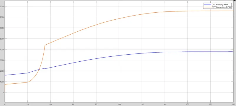
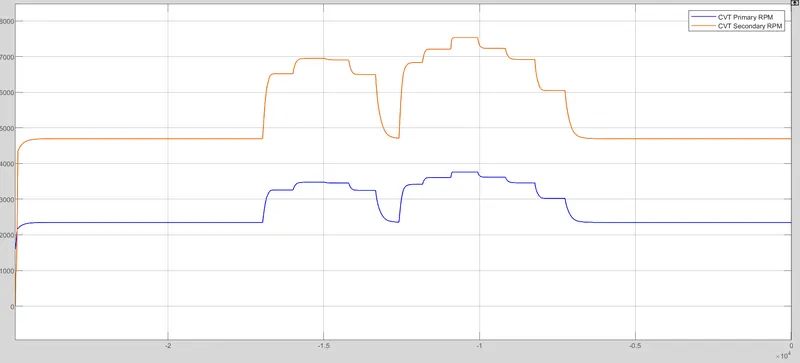
*CVT primary and secondary RPM or cvt shaft speed: According to the gear ratio speed will vary. It will be in gear ratio of primary : gear ratio of secondary. Speed increases as gear ratio increases.
1.2 BAJA ATV WITH DASHBOARD
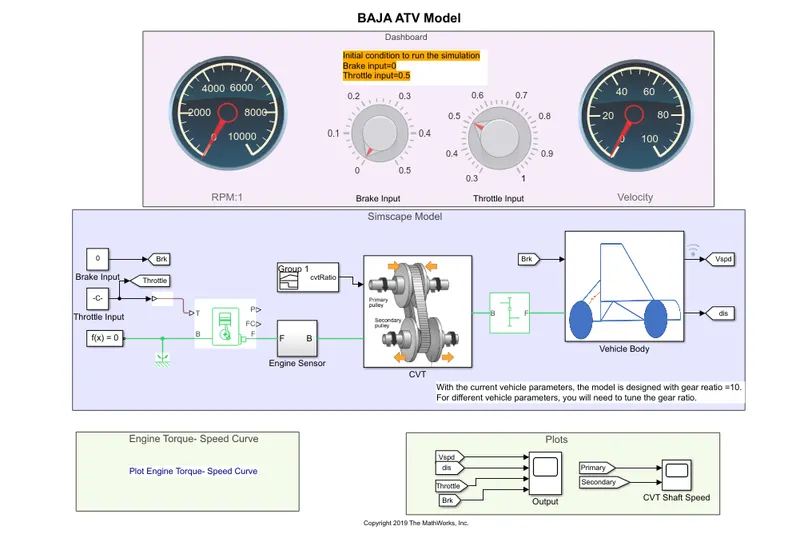
Here in dashboard mechanism throttle and brake inputs are controlled by the user itself. Inputs are generated using constant blocks. The knob in dashboard indicates the corresponding input readings.
The engine rpm guage and velocity guage displays the chsanges done by the respective knobs.
OUTPUTS:
Velocity-distance plot varies according to the throttle and brake. Here no brakes are applied. Speed of vehicle increases with throttle input.
CVT primary and secondary rpm:
2.1 BAJA ATV WITH LOOKUP TABLE
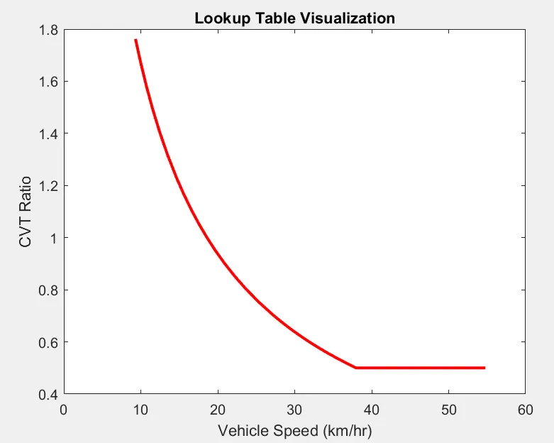
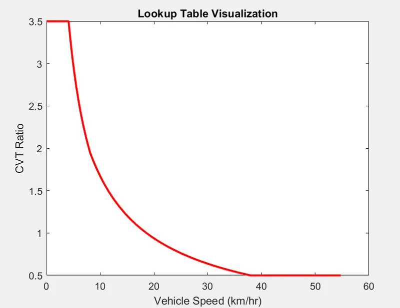
A lookup table is an array of data that maps the input values to output values therby creating a mathematical function.
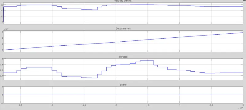
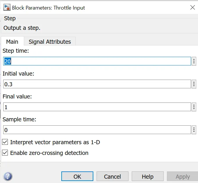
Here cvt ratio signal builder block is replaced with a PS lookup table block. It is loaded in the workspace. For the throttle and brake input a step signal is provied.
OUTPUT:
*Velocity plot along with input signals
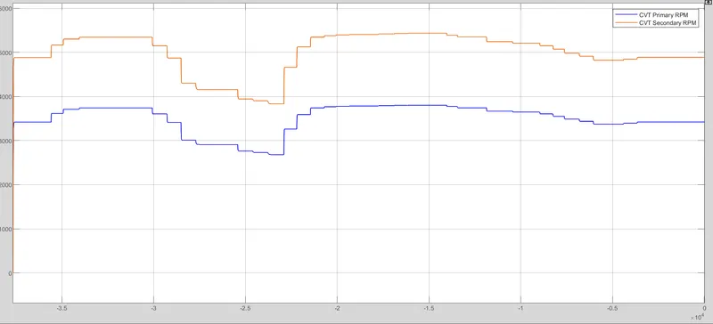
*CVT primary and secondary rpm plots:
2.2 BAJA ATV -CVT MODEL DASHBOARD MAPPED
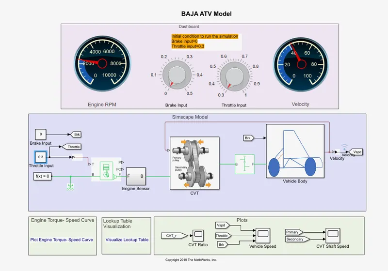
This model also works as same as the previous models. Here cvt ratio and vehicle speed are extracted using 'To workspace' block.
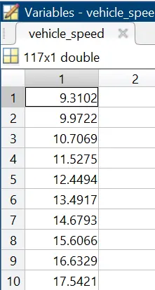
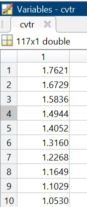
Instead of cvt ratio signal builder block Ps lookup table is used and inside the block table value is set as cvtr, interpolation and extrapolation methods are set as linear.
OUTPUT:
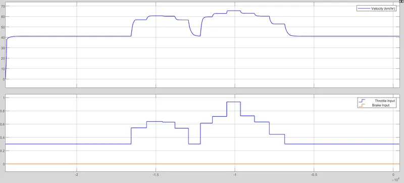
*Velocity plot- when throttle is applied velocity increases and when brake is given it goes down. Here I havenot varied the brake and is set to zero throughout.
*CVT primary and secondary:
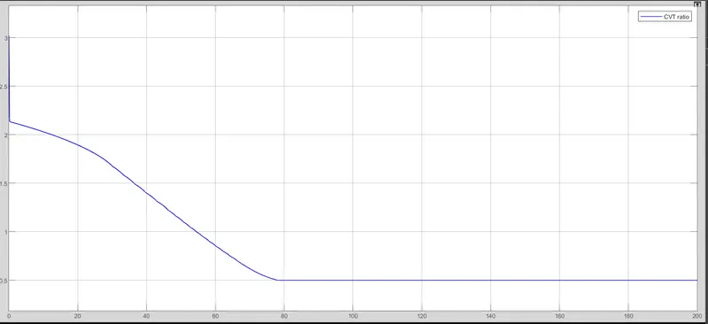
*CVT Ratio plot shown for throttle brake in idle state and when throttle knob is varied.
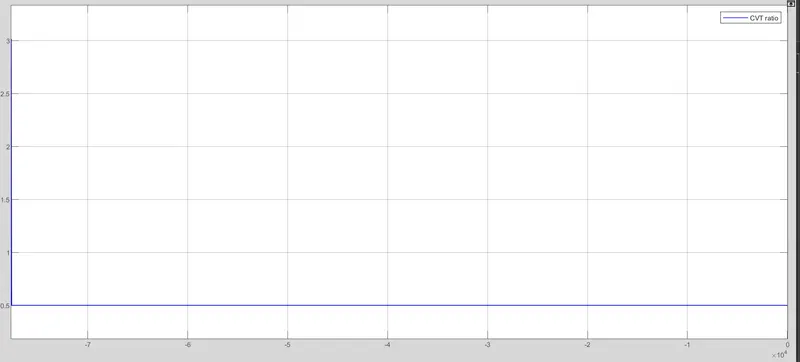
BAJA ATV - CVT ratio rpm:
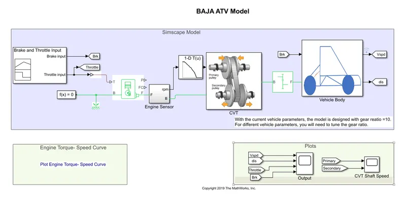
Model diagram-:
Input side is given as throttle and brake signal and a lookup table similar to the previous cases:
OUTPUT:
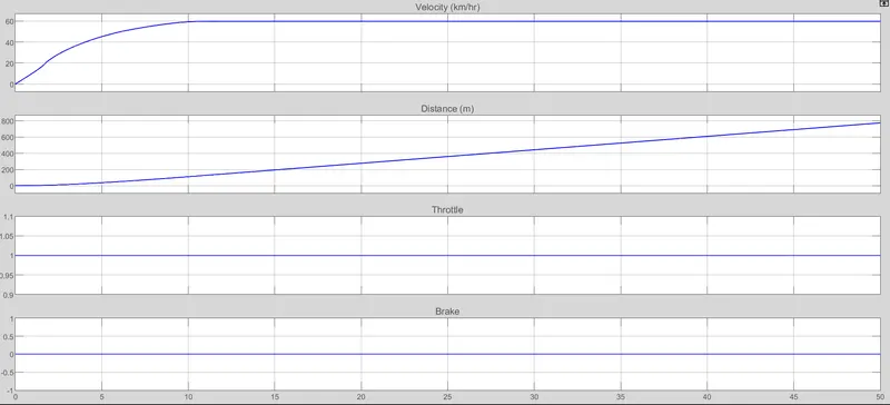
Velocity and distance plotted:
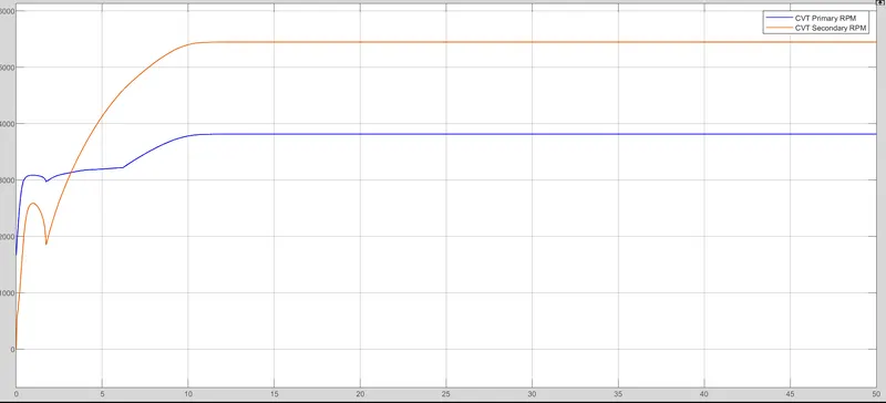
CVT shaft speed plotted:
RESULT:
BAJA ATV model is simulated successfully and the results are obtained as:
*Throttle act as an accelerating input and brakes act as an resistance input.
*Velocity or acceleration, engine speed and shaft speed (primary and secondary) are directly propotional to throttle input and inversely proportional to brake applied.
*CVT ratio is directly proportional to torque and inversely proportional to throttle input.
*CVT primary speed is greater than secondary speed.
REFERENCE:
BAJA ATV Model file
Model examples
Online videos
Wikipedia
https://drive.google.com/file/d/1dko5n5P_LZCL35TH2EjLEt7YIERD7Zp6/view?usp=sharing
https://drive.google.com/file/d/1_14lLqFNG5AyrBbcFcCU-fdm5_Gtq2lU/view?usp=sharing
https://drive.google.com/file/d/1ZSws5tBldEmkuOEGRBnqk2CSDW7o3vy-/view?usp=sharing
https://drive.google.com/file/d/1hMVKm3KqUEKIP2Pm96LPat5NMIT71Zqn/view?usp=sharing
https://drive.google.com/file/d/1IxnhHvz9lmjUrNHY57-o_gl6h8P-kmo6/view?usp=sharing