Week 7 State of charge estimation
Aim:- Simulating the Battery Management System in Battery pack model in different three types of conditions.
What is Battery management System?
Battery management system (BMS) is technology dedicated to the oversight of a battery pack, which is an assembly of battery cells, electrically organized in a row x column matrix configuration to enable delivery of targeted range of voltage and current for a duration of time against expected load scenarios. The oversight that a BMS provides usually includes:
- Monitoring the battery
- Providing battery protection
- Estimating the battery’s operational state
- Continually optimizing battery performance
- Reporting operational status to external devices
Here, the term “battery” implies the entire pack; however, the monitoring and control functions are specifically applied to individual cells, or groups of cells called modules in the overall battery pack assembly. Lithium-ion rechargeable cells have the highest energy density and are the standard choice for battery packs for many consumer products, from laptops to electric vehicles. While they perform superbly, they can be rather unforgiving if operated outside a generally tight safe operating area (SOA), with outcomes ranging from compromising the battery performance to outright dangerous consequences. The BMS certainly has a challenging job description, and its overall complexity and oversight outreach may span many disciplines such as electrical, digital, control, thermal, and hydraulic.
How Do Battery Amanagement System works?
Battery management systems do not have a fixed or unique set of criteria that must be adopted. The technology design scope and implemented features generally correlate with:
- The costs, complexity, and size of the battery pack
- Application of the battery and any safety, lifespan, and warranty concerns
- Certification requirements from various government regulations where costs and penalties are paramount if inadequate functional safety measures are in place
There are many BMS design features, with battery pack protection management and capacity management being two essential features. We’ll discuss how these two features work here. Battery pack protection management has two key arenas: electrical protection, which implies not allowing the battery to be damaged via usage outside its SOA, and thermal protection, which involves passive and/or active temperature control to maintain or bring the pack into its SOA.
Electrical Management Protection: Current
Monitoring battery pack current and cell or module voltages is the road to electrical protection. The electrical SOA of any battery cell is bound by current and voltage. Figure 1 illustrates a typical lithium-ion cell SOA, and a well-designed BMS will protect the pack by preventing operation outside the manufacturer’s cell ratings. In many cases, further derating may be applied to reside within the SOA safe zone in the interest of promoting further battery lifespan.
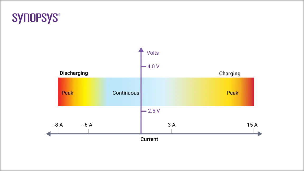
Lithium-ion cells have different current limits for charging than for discharging, and both modes can handle higher peak currents, albeit for short time periods. Battery cell manufacturers usually specify maximum continuous charging and discharging current limits, along with peak charging and discharging current limits. A BMS providing current protection will certainly apply a maximum continuous current. However, this may be preceded to account for a sudden change of load conditions; for example, an electric vehicle’s abrupt acceleration. A BMS may incorporate peak current monitoring by integrating the current and after delta time, deciding to either reduce the available current or to interrupt the pack current altogether. This allows the BMS to possess nearly instantaneous sensitivity to extreme current peaks, such as a short-circuit condition that has not caught the attention of any resident fuses, but also be forgiving to high peak demands, as long as they are not excessive for too long.
Electrical Management Protection: Voltage
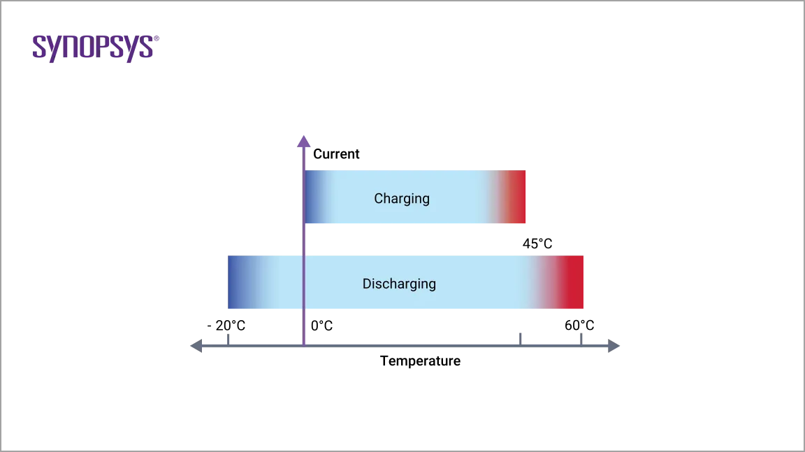
Figure 2 shows that a lithium-ion cell must operate within a certain voltage range. These SOA boundaries will ultimately be determined by the intrinsic chemistry of the selected lithium-ion cell and the temperature of the cells at any given time. Moreover, since any battery pack experiences a significant amount of current cycling, discharging due to load demands and charging from a variety of energy sources, these SOA voltage limits are usually further constrained to optimize battery lifespan. The BMS must know what these limits are and will command decisions based upon the proximity to these thresholds. For example, when approaching the high voltage limit, a BMS may request a gradual reduction of charging current, or may request the charging current be terminated altogether if the limit is reached. However, this limit is usually accompanied by additional intrinsic voltage hysteresis considerations to prevent control chatter about the shutdown threshold. On the other hand, when approaching the low voltage limit, a BMS will request that key active offending loads reduce their current demands. In the case of an electric vehicle, this may be carried out by reducing the allowed torque available to the traction motor. Of course, the BMS must make safety considerations for the driver the highest priority while protecting the battery pack to prevent permanent damage.
Thermal Management Protection: Temperature
At face value, it may appear that lithium-ion cells have a wide temperature operating range, but overall battery capacity diminishes at low temperatures because chemical reaction rates slow down remarkably. With respect to capability at low temperatures, they do perform much better than lead-acid or NiMh batteries; however, temperature management is prudently essential since charging below 0 °C (32 °F) is physically problematic. The phenomenon of plating of metallic lithium can occur on the anode during sub-freezing charging. This is permanent damage and not only results in reduced capacity, but cells are more vulnerable to failure if subjected to vibration or other stressful conditions. A BMS can control the temperature of the battery pack through heating and cooling.
Realized thermal management is entirely dependent upon the size and cost of the battery pack and performance objectives, design criteria of the BMS, and product unit, which may include consideration of targeted geographic region (e.g. Alaska versus Hawaii). Regardless of the heater type, it is generally more effective to draw energy from an external AC power source, or an alternative resident battery purposed to operate the heater when needed. However, if the electric heater has a modest current draw, energy from the primary battery pack can be siphoned to heat itself. If a thermal hydraulic system is implemented, then an electric heater is used to heat the coolant which is pumped and distributed throughout the pack assembly.
BMS design engineers undoubtedly have tricks of their design trade to trickle heat energy into the pack. For example, various power electronics inside the BMS dedicated to capacity management can be turned on. While not as efficient as direct heating, it can be leveraged regardless. Cooling is particularly vital to minimize the performance loss of a lithium-ion battery pack. For example, perhaps a given battery operates optimally at 20°C; if the pack temperature increases to 30°C, its performance efficiency could be reduced by as much as 20%. If the pack is continuously charged and recharged at 45°C (113°F), the performance loss can rise to a hefty 50%. Battery life can also suffer from premature aging and degradation if continually exposed to excessive heat generation, particularly during fast charging and discharging cycles. Cooling is usually achieved by two methods, passive or active, and both techniques may be employed. Passive cooling relies on movement of air flow to cool the battery. In the case of an electric vehicle, this implies that it is simply moving down the road. However, it may be more sophisticated than it appears, as air speed sensors could be integrated to strategically auto-adjust deflective air dams to maximize air flow. Implementation of an active temperature-controlled fan can help at low speeds or when the vehicle has stopped, but all this can do is merely equalize the pack with the surrounding ambient temperature. In the event of a scorching hot day, this could increase the initial pack temperature. Thermal hydraulic active cooling can be designed as a complementary system, and typically utilizes ethylene-glycol coolant with a specified mixture ratio, circulated via an electric motor-driven pump through pipes/hoses, distribution manifolds, a cross-flow heat exchanger (radiator), and cooling plate resident against the battery pack assembly. A BMS monitors the temperatures across the pack, and open and closes various valves to maintain the temperature of the overall battery within a narrow temperature range to ensure optimal battery performance.
Description of model:-
This is the main dashboard of this model
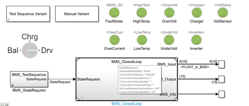
This is how the BMS implemented in MATLAB/Simulnk along with the battery pack.
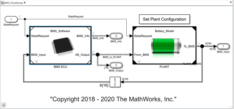
This is how BMS modelled inside in the subsystem of BMS ECU
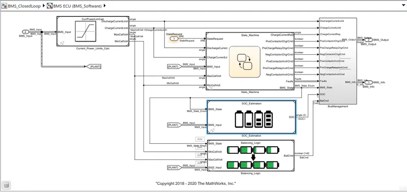
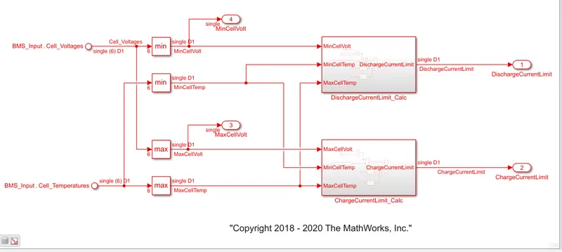
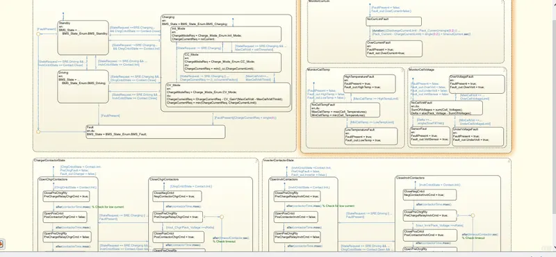
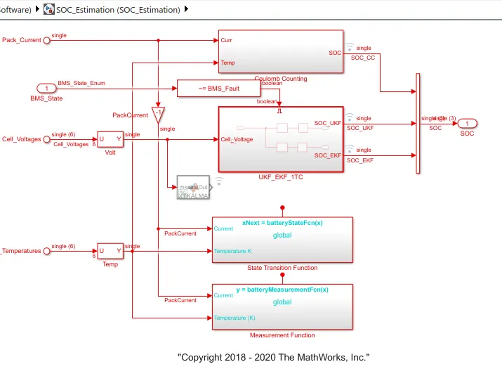
In this subsystem modelled the inside of Current_power_limit_calc subsystem we calculate the charge current limit and discharge current limit using lookup table in this lookup table we put the high and low temp discharge current for discharge current limit calculate and for calculate charge current limit we put high and low temp charge current. then next in the state machine we put the algorithm using state flow the algorithm as for monitoring fault as temp and voltage in second we control the charging as constant voltage and constant current mode and in this another one is driving mode and in next algorithm is for charger contactactor and inverter contactor it is based on open and closed. and then the next subsystem is SOC estimation in this we eastimate SOC using 3-4 methods in this we use kalman filter and Columb counting method use. In this we 3-4 systems are used because for observation which system gives better SOC. Then next wew implement ballancing logic for controling the over voltage , undervoltage, soc control, for resistance control, under current, over current. then from this all subsystem output we will give to the bus selector to connect the battery Pack.
Subsystem Current power limit Calculations:-
Subsystem State Machine:-
Subsystem of SOC Eastimation:-
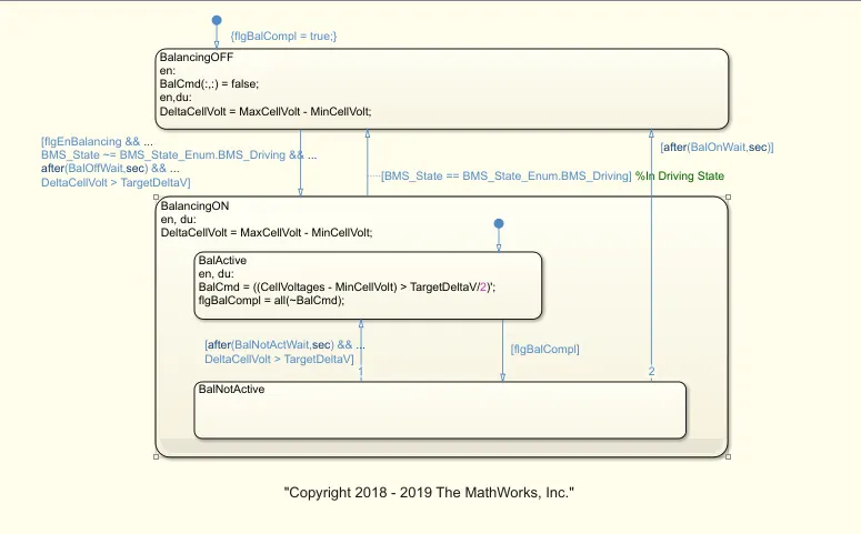
Subsystem of Balancing logic:-
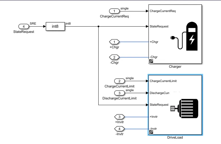
Plant Subsystem:-
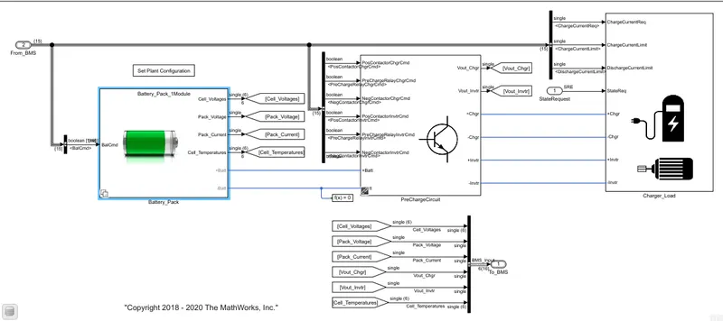
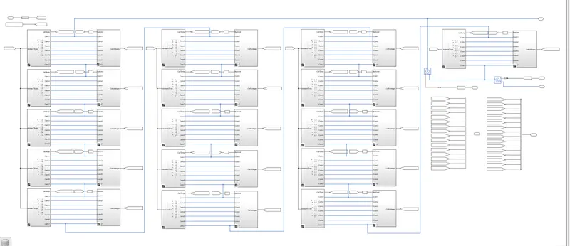
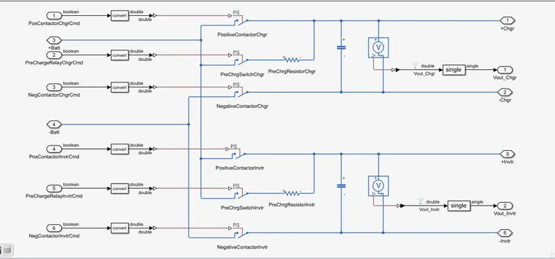
This model includes two variants of Battery Pack (1] One module with 6 cells in series, 2] 16 modules with 96 cells in total). Battery Pack is connected to Charger / Load via Precharge Circuit and contactors. Precharge circuit is required ensure there is no sudden rush of current in/out of battery pack when connected to Charger or Load with large voltage difference. Closing or opening precharge contactors is done by BMS.
Battery Pack Modelling:-
1] One Modules SIX cells in series:-
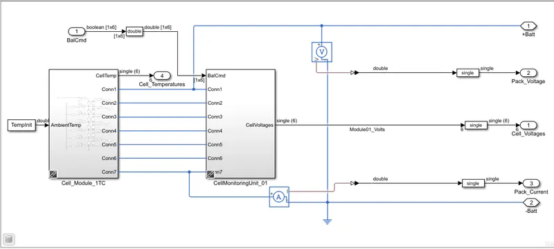
Cell Modules:-
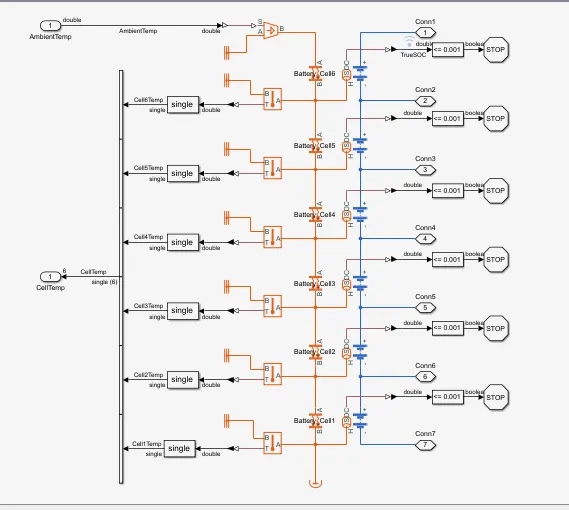
Cell Monitoring Unit:-
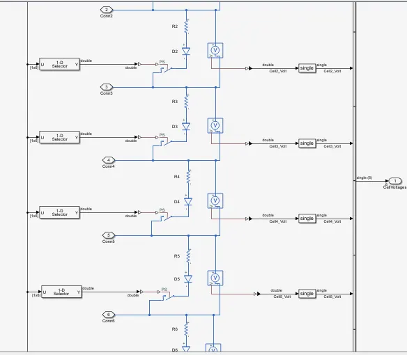
2] 16 Modules with 96 cells in total:-
Precharge Circuit Subsystem:-
Charger load Subsystem:-
Question 1] Simulate the 3 test cases from harness dashboard and write a detailed report on the results.
Answer:-
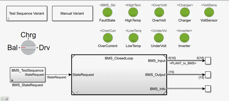
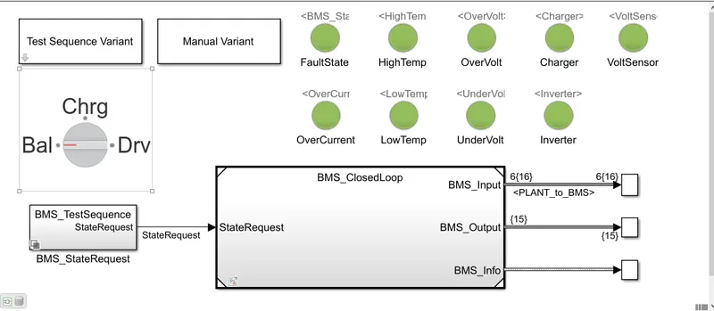
From the above MATLAB model we are simulating 3 test cases from harness dashboard to find out the fault condition in BMS and the below image shows the dashboard where we can get the information related to the faults like overvoltage, undervoltage, high temperature, over current and inverter related faults. If there is any fault condition the indicators will turn to red colour otherwise it shows the green indiation means there is no fault and the system is safe.
We can also know the informaytion like the battery pack is in which condition at present moment like the mode of operation called balancing mode, charging mode, and discharging mode.
Now we can apply test
Test 1] :- Discharging, Charging and Balancing/ At BMS level test condition for both driving and charging.
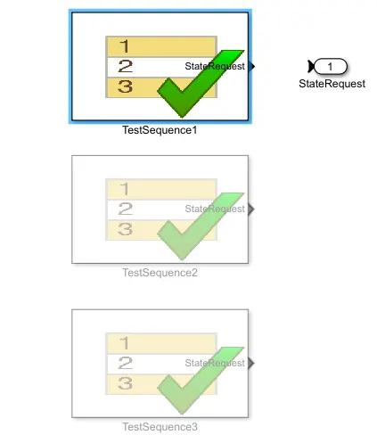
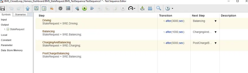
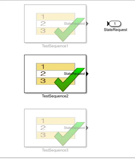
From the test sequence variant we can implement the three test conditions.
Results:-
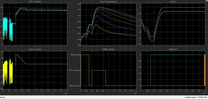
Cell Voltages and Pack Current:-
We can observe the constant current and constant voltage characteristics of the battery pack initialy the cell voltage is around 3.8V and the cell current is Zero when the battery is fully discharged.
At time instant of 0.4sec the cell voltage is gradually increased from 3.8 to 4.2 V at this same instant of time the peak current of cell increasedd from 0 to 30A and it is constant till 0.5sec this phase of cell is called a CC mode and then it gradually reduces to zero at 0.7 sec.
At time 0.5sec the cell voltages are increased to 4.2V and then became constant from 0.7 sec till the ned of simulation time or till is completely charged this phase is called as constant voltage CV mode usually the CV mode takes longer time period than the CC mode.
Comparison of BMS state condition with cell voltages, pack current, cell temperature, SOC and cell Balancing:-
1] Discharging Mode/BMS Driving:- At time instant 0 to 0.4sec.
Cell voltage reduced from 4.2V to 3.7V.
Pack current reduced to 0.
SOC is initially is of 80% and reduced to 30%.
Cell temp increased from initial 289.15 to 300K and difference in increase is 20K.
Cell balancing is idle in this time period.
2] charging Mode/BMS Driving:- At time instant 0.4 to 0.9sec.
Cell voltages are constant from 4.2V this is called CV mode.
Pack current increased from 0 to 30A and reached its full capacity and then after reduces to zero in this CV mode.
SOC is initially is of 30% at this stage and increased to 100% or 1 to its full capacity.
Cell temperatures increased from initial 300K to 315K and difference in increase is 15K and gradually refuced because the cellas are fully charged.
Cell balancing is operating in this time period to ensure the maximum capacity reached by all the cells while charging in equal mode of operation.
State of charge (SOC):-
As we can observe the SOC is eastimated using different methods like
1] Columb Counting:- from the result the yellow graph showing this method where the SOC reached to 100% at time 0.7 sec.
2] UKF kalman filter:- SOC eastimation from this method is 93%.
3] EKF kalman filter:- SOC eastimation from this method is 93%.
Both the kalman filter are overlapping each other and giving the output is also same.
Hence there is no fault is observed from the DAashboard where all the indication is green.
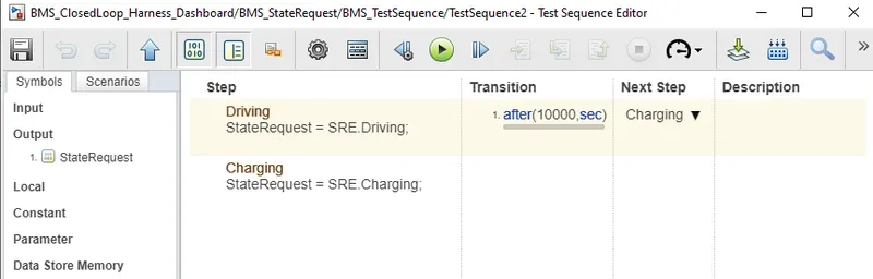
Test 2]:- disCharging and no Balancing/ At BMS level test condition for driving.
In this test No fault Found
Results:-
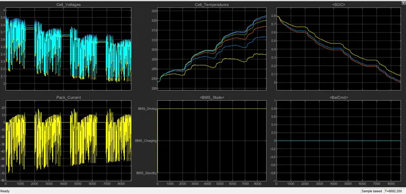
Comparison of BMS state condition with cell voltages:- Pack current, cell temperature, SOC and cell balancing.
1] Discharging mode/ BMS driving:- At time instant 0 to till end of the simulation
Cell voltages reduced from initial 4V
Pack current reduced to 0.
SOC is initially is of 80% and reduced to 0%.
Cell temp increased from initial 289.15 to a maximum recorded as 323K and difference in increase is different and comparatively less with the maximum recorded as 323K for other output graphs.
Cell balancing is idle in this time period.
Henece there is no Fault observed from The Dashboard where all indication is green.
Test 3] :- disCharging and no Balancing/ At BMS level test condition for both driving and charging.
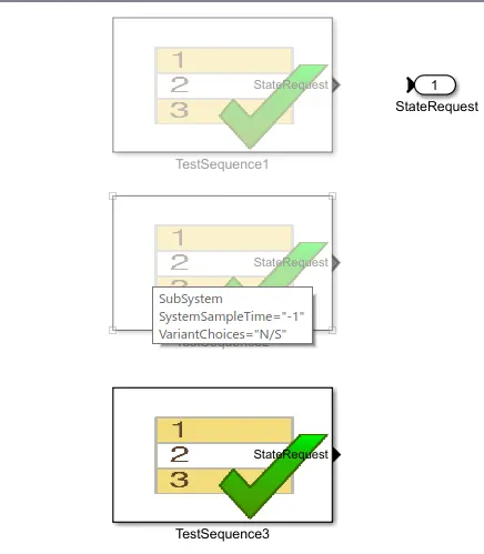

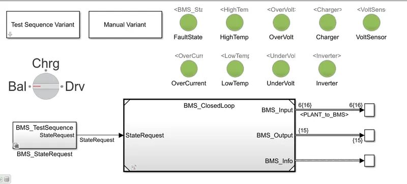
Result:-
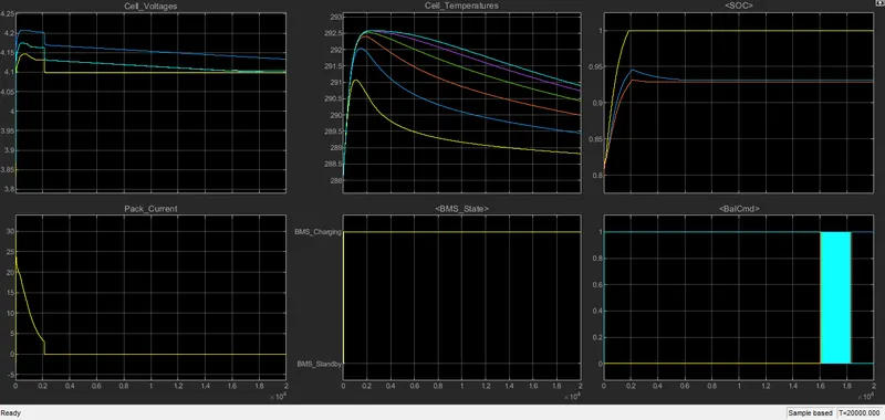
Comparison of BMS state condition with cell voltages,pack current, cell temperature,SOC and cell balancing.
1] Charging Mode/BMS charging:- At time instant 0 to till end of the simulation.
Cell voltages and pack current combine:-
We can observe the constant current and constant voltage charactersistics of a battery pack. From initially time period of 0sec the cell curent increased to 30A and the cell voltages also gradually reached to 4.2V this phase of opertaion is called constant current mode.
At time instant of 0.2sec the cell voltages are gradually becomes constant till the end of the full charging voltage capacity of battery pack and at this time instant the current is gradually reeduced to 0. so this mode of operation is called constant voltage mode.
Generally cell manufacturers design the CC mode till the cell reaches 80% of its full capacity and from there the remainingg 20% will be considered as CV mode.
State of charge (SOC):-
SOC is initially is of 80% at time instant of 0.2sec this is increased to 100% or 1 to its full capacity with variation in different SOC eastimation methods.
As we can observe the SOC is eastimated using different methods like
1] Columb counting:- From the result the yellow graph is showing this method where ythe SOC reaches to 100% at time 0.2sec.
2] UKF kalman filter:- SOC estimation from this method is 93%.
3] EKF kalman filter:- SOC estimation from this method is 93%.
Both the kalman filter methods are overlapping each other and give same results.
Cell Temperature:-
Cell temp increased from initial 288K to a maximum recorded as 292.3K with difference in temp rise is recorded with pother cell temp estimation graphs.
Cell balancing is operating int this time period to ensure the aximum capacity reached by all the cells while charging in equal mode of operation and at time period of 1.8 sec the cell balanicng is cut off.
Henece there is no Fault observed from The Dashboard where all indication is green.
Conclusion:-
As per simulating three different types of cases we can conclude that the Columb Counting method is best suitable for the battery management system model. It can gives 100% state of charge.
Question 2] What is coulomb counting? Refer to the above model and explain how BMS implements coulomb counting for SOC estimation ?
Answer:-
The battery parameters detection is one of the most important issue in control and management of a BMS. It includes cell voltage measurement and current detection. Estimation of SOC and other battery states imposes high requirements on cell voltage precision.
State of charge (SOC) is the level of charge in an electric battery relative to its capacity. The units of SOC are percentage points. An alternative form of the same measure is the Depth of Discharge (DOD), inverse of State of Charge (SOC).
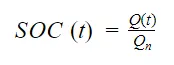
SOC is defined as the ratio of its current capacity (Qt) to its nominal capacity (Qn).
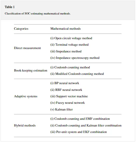
Different methods to calculate SOC:-
- Direct measurement:- This method uses physical battery properties, such as the voltage and impedance of the battery.
- Book-keeping estimation:- This method uses discharging current as the input and integrates the discharging current over time to calculate the SOC.
- Adaptive systems:- The adaptive systems are self-designing and can automatically adjust the SOC for different discharging conditions. Various new adaptive systems for SOC estimation have been develop.
- Hybrid methods:- The hybrid models benefit from the advantages of each SOC estimation method and allow a globally optimal estimation performance.
Book keeping estimation:-
Book-keeping estimation method uses battery discharging current data as input. This method permits to include some internal battery effects as self -discharge, capacity-loss, and discharging efficiency.
Two kinds of book-keeping estimation methods have been employed:-
Coulomb counting method and modified Coulomb counting method.
Coulomb counting method :-
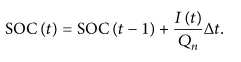
It is a technique used to track the state of charge of a The Coulomb counting method measures the discharging current of a battery and integrates the discharging current over time in order to estimate SOC.
SOC is calculated by using following equation.
Modified Coulomb counting method:-
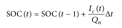
To improve the Coulomb counting method,a new technique called modified Coulomb counting method is proposed. The modified Coulomb counting method uses the corrected current to improve the accuracy of estimation.
The corrected current is the function of discharging current. There is a quadratic relationship between the corrected current and discharging current of battery. By practice of experimental data, corrected current is calculated by

where K2, Kl, KO are constant values obtained from the practice experimental data.
In modified Coulomb counting method . SOC is calculated by the following equation
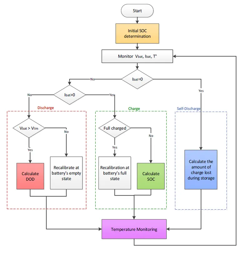
Basic proposed flowchart for estimation of SOC:-
SOC Estimation Block in BMS Model:-
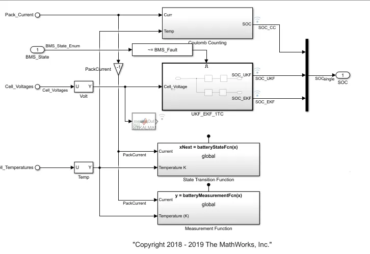
Columb Counting method model:-
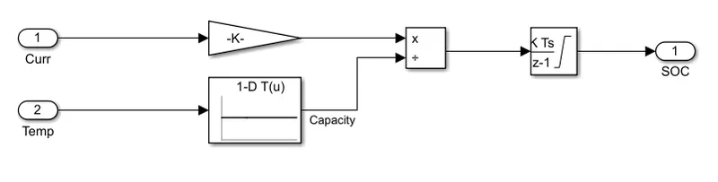
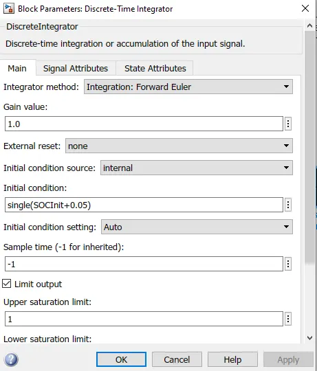
In this the current and temperature gives as input and the ouput meet SOC using lookup table block, discreate time integrator block. In this discteate block we will give SOC initial values+0.05 as initial condition.
Parameter:-
This algorithm has allowed the system to operate in safe conditions by respecting the secure operating area of the Li-ion batteries in charge and discharge modes. It has proven a good reliability and the error estimation of the instantaneous capacities has been only about 2%.
Thank You
Dharmesh Bonde...