Week 7 State of charge estimation
1.Simulate the 3 test cases from harness dashboard and write a detailed report on the results
The below diagram is the simulation of harness dashboard.
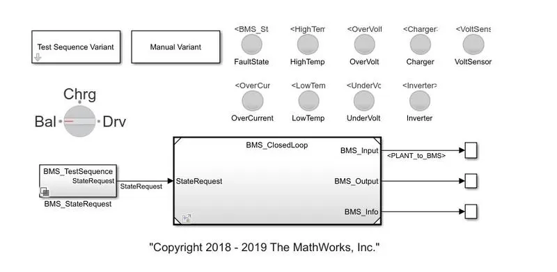
In the above image we see that it has a subsystem in which it has other BMS simulation and battery controller connections. The test sequence variant is used to select the test case. There are nine indicators used to display the faulty section for servive or to warn the user.
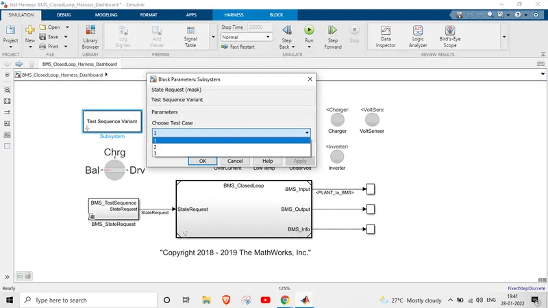
In this didgram shows how to select the case of testing sequence.
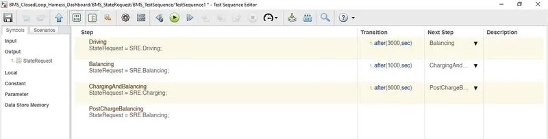
This above shows the case selected and its deatils, according to condition the after 3000 secs od driving the battery ghas to balance and then it should go to charging condition after 1000 secs then after 5000 secs the battery should has to be in postcharging condition.
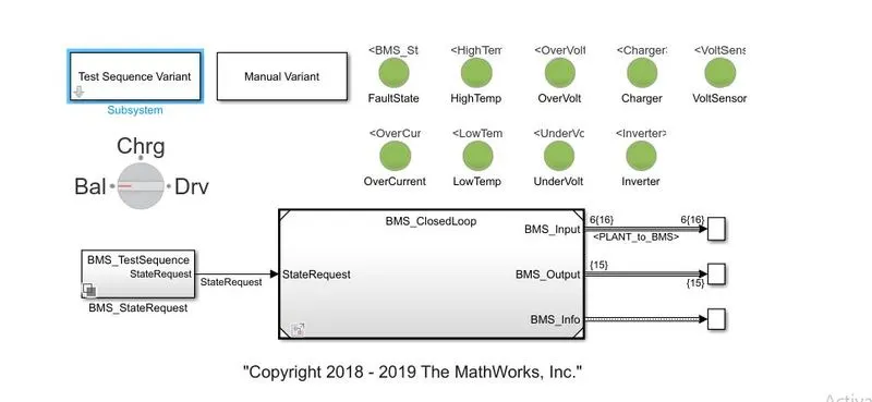
After running the simulation we see that all the indicators are green, hence those blocks are working without any fault. The test sequence feeds the details to BMS loop.
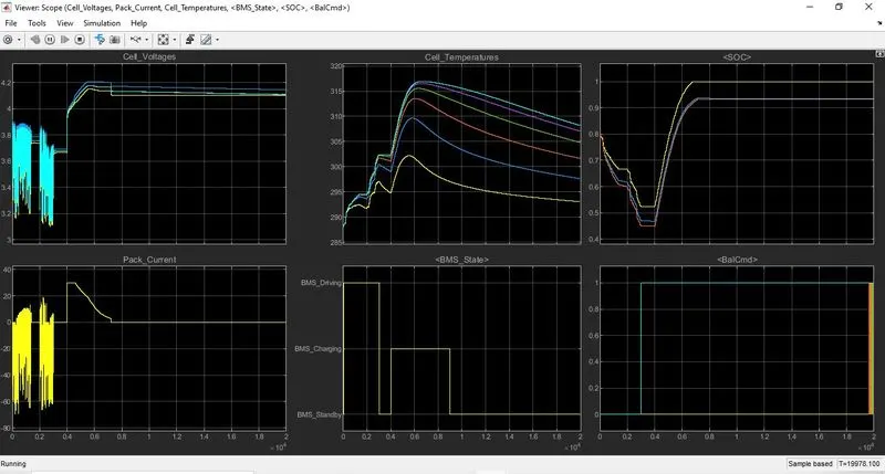
This graph shows the BMS state and SOC status. Till 3000 secs the voltage and current depends upon the drive cycle feed after 3000 secs the BMS starts to monitor the battery and then charges the battery to its max SOC and attains post charging condition.
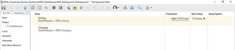
The condition is for case2 and it is fed to the BMS, according to condition the battery has to charge after 10k seconds.
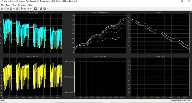
By the condition applied, the battery has to charge after 10000 secs but it dosent charge again due to its fault condition.
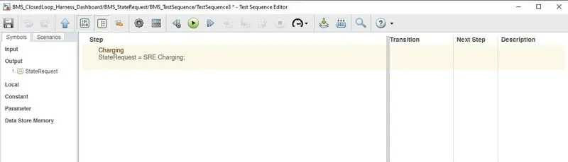
This condition is for case 3, it says that the battery should be in only charging condition.
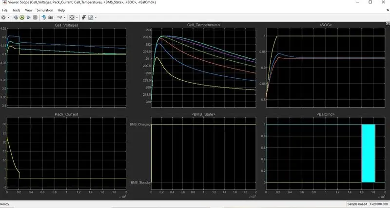
Hence the above graph shows that the battery is continoiusly charging and its is as per the condition applied. The temperature is high at starting charge condition and decreases. Thus all the three test case are tested and the graoh are plotted.
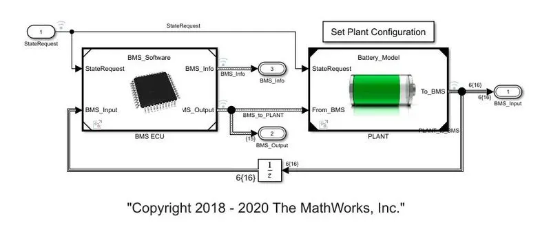
2.What is coulomb counting? Refer to the above model and explain how BMS implements coulomb counting for SOC estimation ?
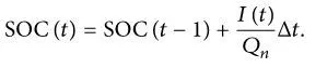
The Coulomb counting method measures the discharging current of a battery and integrates the discharging current over time in order to estimate SOC. Coulomb counting method is done to estimate the discharging current and previously estimated SOC values, But there are several factors that affect the accuracy of Coulomb counting method including temperature, battery history, discharge current, and life cycle.
SOC is calculated by the following equation-
To improve the Coulomb counting method, a new technique called modified Coulomb counting method is proposed. The modified Coulomb counting method uses the corrected current to improve the accuracy of estimation. There is a quadratic relationship between the corrected current and discharging current of battery and corrected current is calculated by the following formulae.

where
k1, k2 and k3 are constant
Hence the SOC is calculated by the below formulae

The below block is the simulation of BMS coulomb counting for SOC which has two input as current and temperature.
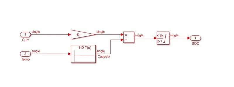
Thus we opened the coulomb block and we can observe there the current and temperature are fed to a multipler and given to discrete time signal to get the SOC. The BMS monitors temperature, current, and voltage etc.., and feds to the respective inputs, to make the battery in safe operating mode. Thus we have seen that the SOC is monitered by the BMS and seen BMS implementation of coulomb counting for SOC estimation.