Week 7 State of charge estimation
1) Simulate the 3 test cases from the harness dashboard and write a detailed report on the results.
Ans) The link given in the question above was used to downlod the project. The project consists of battery and bms models which are driven through various test cases to evaluate the battery dynamics and bms action under different usage scenarios. The BMS closed-loop harness dash board is shown in the figure below:
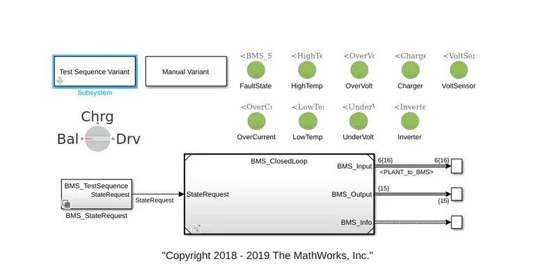
As can be seen from the figure above, the lights indicate all sorts of possible faults which can happen in the battery pack. The green light indicates that there is no fault at the moment. The BMS_ClosedLoop block in the figure above contains battery and BMS blocks along with charger and load models. This is shown in the figure below:
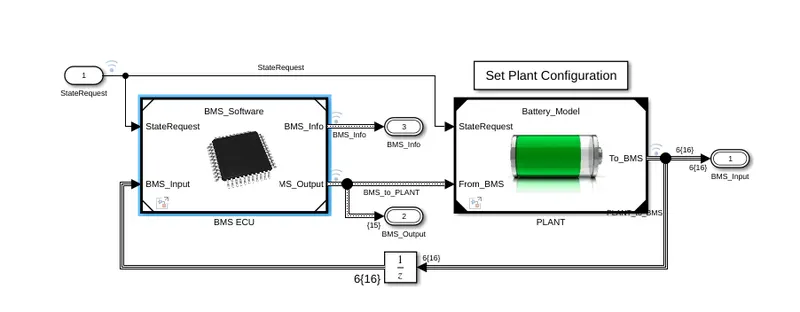
The Battery_Model is controlled by BMS. In the lingua franca of control systems, Battery_Model is the plant and BMS is the controller. The Batter_Model contains within it models of battery pack, charger and load as shown in figure below:
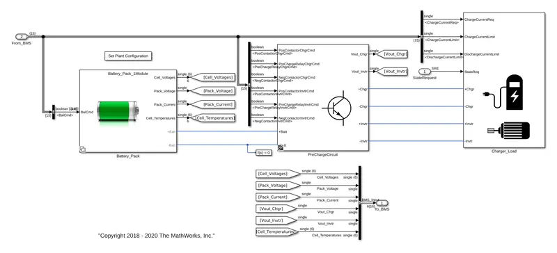
The BMS model contains various control algorithms like SOC estimation and balancing circuits as shown in the figure below:
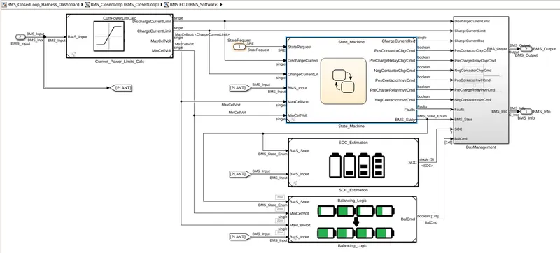
Now, we need to simulate the three test cases and evaluate the simulation results.
Test Case 1:
In order to simulate the first test case, we need to select the first test sequence from Test Sequence Variant block as shown in figure below:
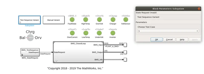
As can be seen from the model above that all the lights are green indicating that there are no faults in this test case.
Now the first test case has the following sequence of states:

According to the figure above, as the simulation starts, the first state which gets activated with the simulation is the Driving State as can be seen in the figure above. This first states continue for 3000 seconds. After 3000 seconds, the next state or step which is requested is the Balancing state which continues for the next 1000 seconds. After Balancing, the ChargingandBalancing states is requested which goes on for 5000 seconds and the last state is PostChargeBalancing.
Now we can look at the simulation results, how BMS and Battery model reacts to the above states.
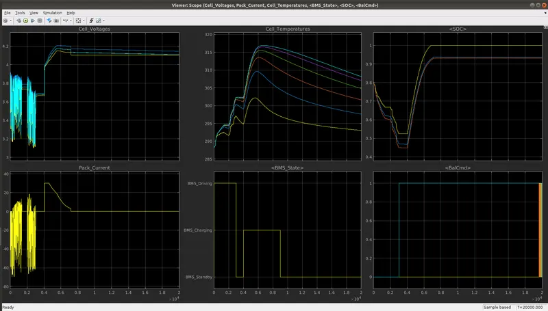
It can be observed from the simulation result above, that initially as the simulation began, the battery pack was charged at 80%. As the first state was a driving state for 3000 seconds, the battery pack was discharged as can be seen from the SOC, Pack_Current, Cell Voltages and Cell Temperatures. After 3000 seconds, the vehicle stops and the battery is in the balancing mode for next 1000 seconds. During this period, no current is drawn or supplied from or to the pack. Since the cells in the battery pack are balancing themselves in this state, the cell voltage seem to converge during this time as can be seen from the simulation result above. After 1000 seconds of balancing mode, the battery pack is charged which can be clearly observed from the simulation results as SOC, voltage, the temperature of the battery pack begin to increase. The battery pack is charged to 90%. The charging state is carried out for 5000 seconds and after that PostChargeBalancing is activated. During this state the cells try to balance themselves thus their individual cell voltages converge to the same value.
Test Case 2:
For the second test case, we need to select 2 in the Test sequence variant block as shown in the figure:
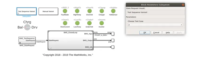
Again for this case, there isn't any fault as all the lights are green.
The states for this case are shown in figure below:
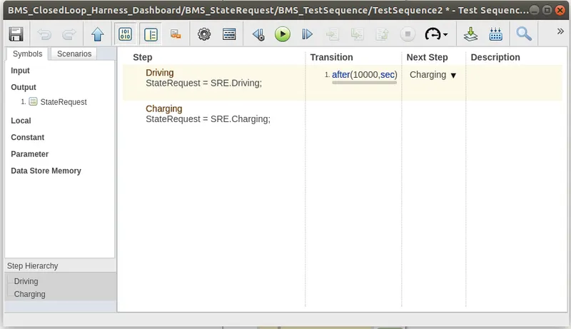
The figure above shows that this test sequence has only 2 states, the simulation begins with the driving state for 10000 seconds and then charging state begins after that. The simulation result is shown below:
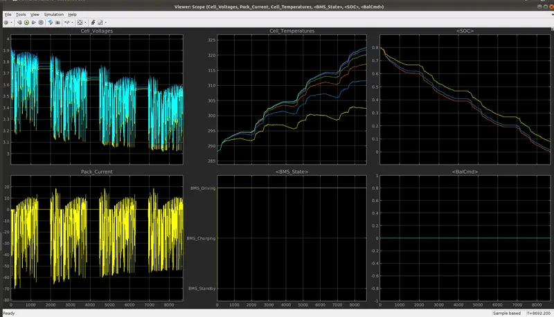
As expected, the battery pack SOC and Cell Voltage keeps on falling because the battery is being discharged and the cell temperatures are rising due to continuous discharge.
Test Case 3:
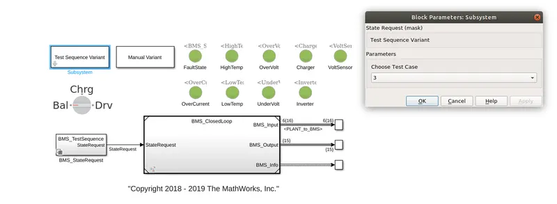
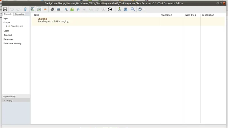
The third test case has been selected from the Test Sequence Variant Block and it has only one state which is the charging state as shown in the figures below:
The simulation result is shown below:
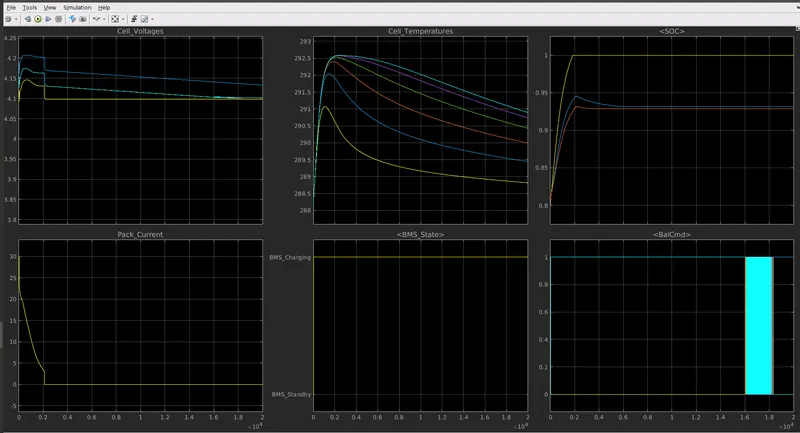
According to the simulation results, the battery pack is in charging mode only. And the charging method used to charge the battery pack is CC-CV method. Once the pack is fully charged, the charging current drops to zero and packs in standby mode where balancing occurs and cells try to balance each other thus converging each cell voltage to the same value.
2)What is coulomb counting? Refer to the above model and explain how BMS implements coulomb counting for SOC estimation ?
Ans) Coulomb Counting is method of estimating SOC of a cell or a battery pack by integrating the total current that went in or out of the cell during a driving cycle with respect to the time. It is a very simple method for estimating SOC but it doesn't work in applications where accuracy in estimating SOC is required like EV applications.
In the model above, the BMS implements the coulomb counting algorithm in the following way:
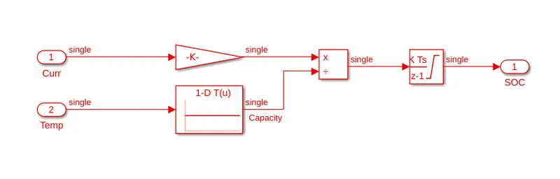
In the model shown above, the current is multiplied by a gain. The gain actually is 1/(total capacity). This helps convert the units from Amps to a unitless quantity which is SOC. This model also takes temperature into account as can be seen by the lookup table in the figure above. The reason for this is that the current/power which can be extracted from a cell at any moment is dependent on SOC and temperature, thus a very high current drawn from the cell can cause the cell to go below voltage limit very quickly thus affecting its effective capacity and high current leads to high temperature which further escalates the process.