Week -2
1) Simulink model of a doorbell using solenoid
The simulink model of a doorbell using solenoid is made as shown in the figure below:
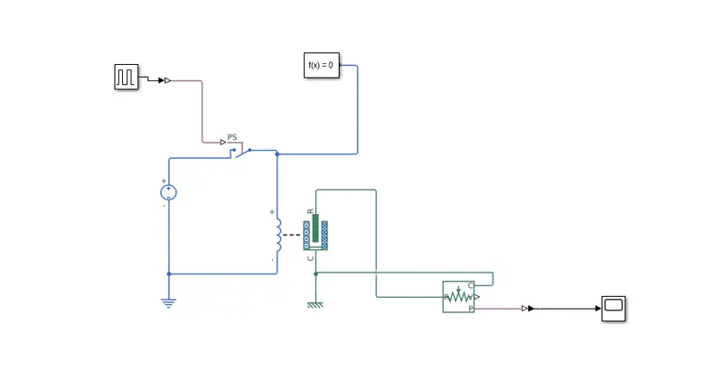
The model was created using the following elements:
1) Voltage source: It provides a potential difference across the solenoid.
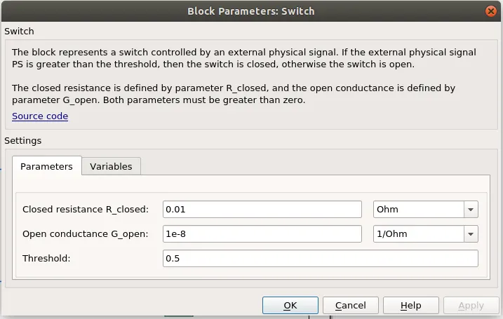
2)Switch controlled by external signal: An ideal switch controlled by an external signal. The default position of the switch is open. The switch closes when the value of the external signal is greater than the threshold value of the switch. From the figure below, the threshold value is 0.5. To close the switch the value of the external signal should be greater than 0.5.
3) External signal source: The external signal source used for this problem is a pulse generator.
4) Solenoid: Solenoid is an electromechanical device used as a doorbell here.
5) Translational Force Sensor: This element is used to sense the motion of plunger of a solenoid.
6) Scope: This is used to plot the simulation results.
7)Electrical and Mechanical translational reference: References of respective domains are used to represent ground, frame, etc.
8) Solver Configuration: To define solver settings used for simulation.
Results:
The problem statement was that when the switch is closed the electromagnet receives electrical power from the battery and pulls the metal arm to hit the bell producing sound. We needed to create a situation where the switch is closed for 2 seconds and then released and observe the physical movement of the plunger.
Ans: Thus when the switch is closed (threshold value is greater than 0.5), the circuit is complete and the solenoid receives electrical power from a battery and it pulls the metal plunger to hit the bell. This means that when the switch is closed, the air gap of distance between the metal arm or plunger and the bell should be zero. When the switch is release or open, the air gap or distance between plunger and bell goes back to its default or initial value of 5mm. This is shown by the simulation result below:
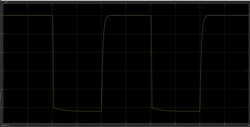
The X axis represents the time passed and Y axis represents the air gap between metal arm and bell.
It can be observed that at time 2 seconds, air gap goes to zero for 2 seconds because switch is closed for 2 seconds and at 4th second the switch is released and thus air gap again increases to 5 mm(default position).
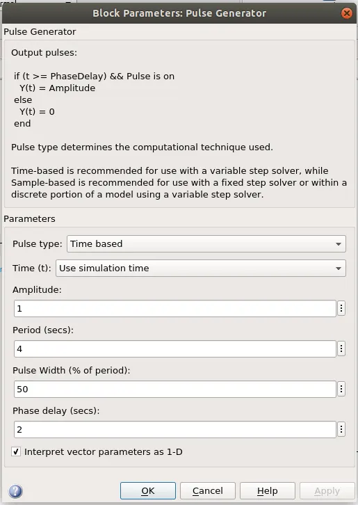
In order for solenoid to behave like this, the pulse generator which provides the external signal to switch had to be tuned in the following way as shown in figure below:
2) Use a thermistor to sense the temperature of a heater & turn on or turn off the fan as per below condition:
Temperature source: 20°C from 0 to 10 seconds, 27°C from 10 to 30 seconds, 23°C from 30 to 50 seconds
Fan conditions: ON if the temperature above 25 °C, OFF otherwise
The simulink model of the system which uses a thermistor to sense the temperature of heater and turn on and turn off fan is shown in figure below.
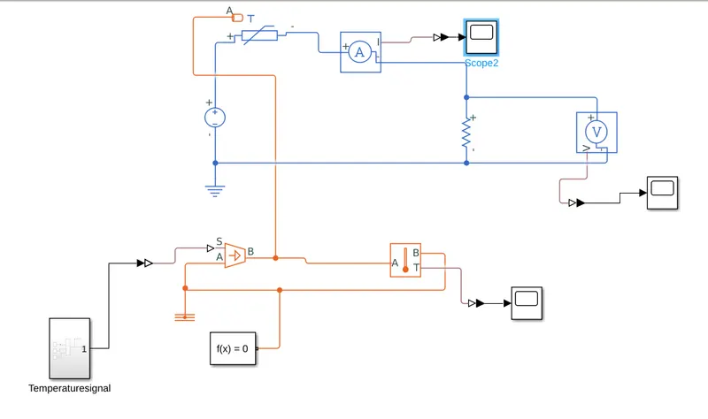
In simulink model above the fan is modeled as a resistor which is in series with a thermistor and voltage source. Current sensor is used to sense the current flowing in the electrical circuit when the thermistor switch is closed.
Thermistor switch is a device whose resistor changes with temperature. Resistance of the thermistor used in the above simulink model varies inversely with temperature. So as temperature of the themistor goes above 25 degree Celcius, resistance of thermistor drops and it starts conducting.
This can shown from the simulation result of current flowing through the circuit flowing below.
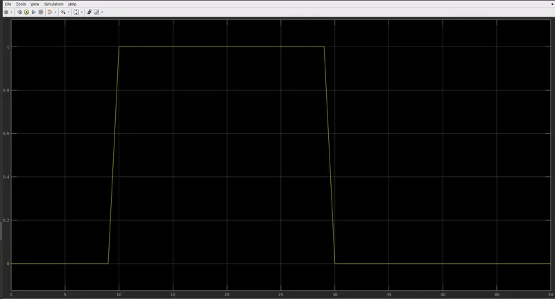
As can be seen from the figure above, the current rises at 10 seconds because that is the time when the temperature of the thermistor rises above 25 degree Celcius and it falls to zero at time 30 seconds because the temperature of the thermistor falls below 25 degree Celcius.