Week - 4
1) Control Logic for a washing machine:
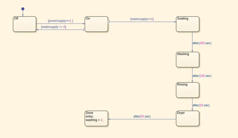
The control logic for washing machine as per given rules is shown in the figure below:
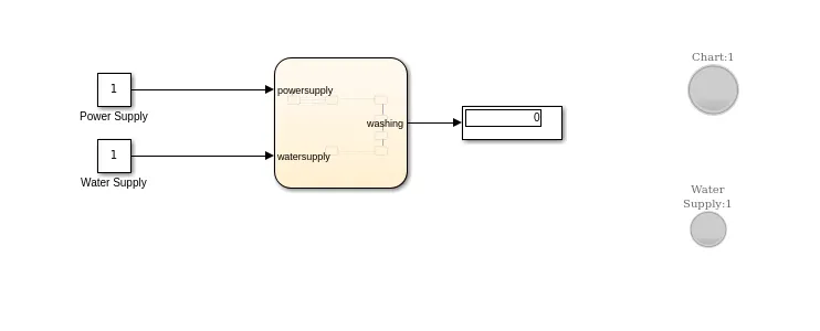
The overall simulink model is shown in the figure below:
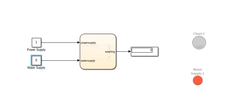
Now when Water supply is Off but Power supply is On, the simulation stops and water supply LED turns red as shown in figure below:
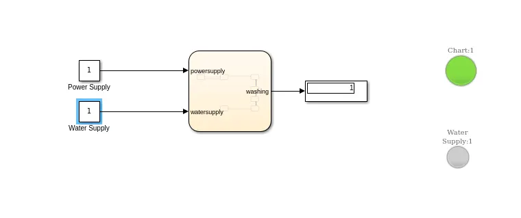
When both Power supply and water supply are on then the whole washing process is done successfully and this is indicated by LED turning green as shown in figure below:
2) Gear Shift Logic
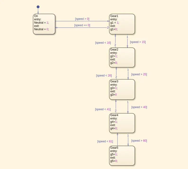
The gear shift control logic is implemented using Stateflow as shown in figure below:
The simulink model of whole system is implemented as shown in figure below:
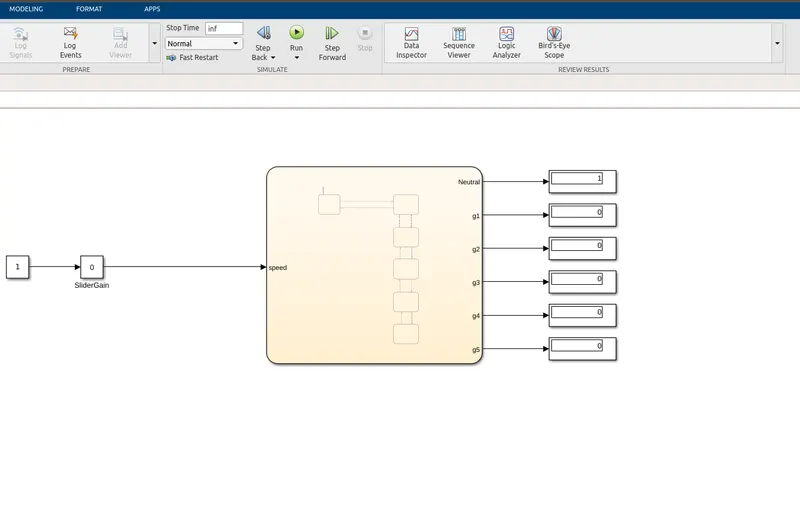
As shown in the figure above, the speed is varied while the simulation is running using a slider gain block. As speed varies, the gear changes as per Stateflow chart.