Week 7 - Simulating Fluid Sloshing effect inside a Gear-box
Objective:
Part 1:
- 20% Immersion, Fluid - Engine oil.
- 30% Immersion, Fluid- Engine oil.
- 20% Immersion,Fluid-n-heptane (c7h16).
- 30% Immersion,Fluid-n-heptane (c7h16).
Part 2:
- What is Dynamic meshing? Give some other examples where dynamic meshing can be used.
- What is the fluid Sloshing effect? Discuss whether the sloshing effect is good or bad? Explain.
- What is the use of UDF?
- Discuss the common errors that occurred in the simulation. A] 'Dynamic mesh failed' error. B] 'Negative cell volume detected' error
Answer:
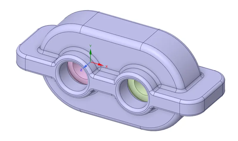
Following is the model received to perform multiphase simulation using dynamic mesh in Ansys Fluent.
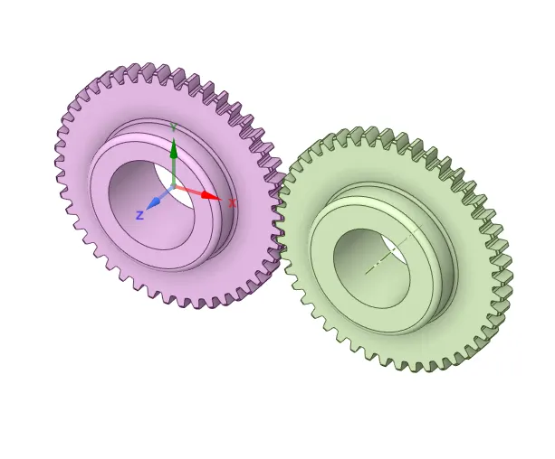
After hiding the housing shown in the above image, following set of gears can be shown.
The simulation will be performed on 2d geometry. The 2d geometry needs to be extracted from the above 3d geometry. The extract 2d surface, first three datum planes has been created on the datum axis of the gear set shown in the below image.
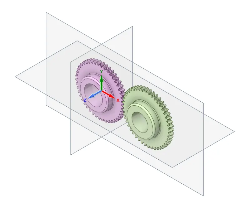
The command, split by plane, has been used to cut the gears from the middle using the plane shown in the below image.
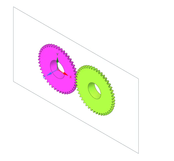
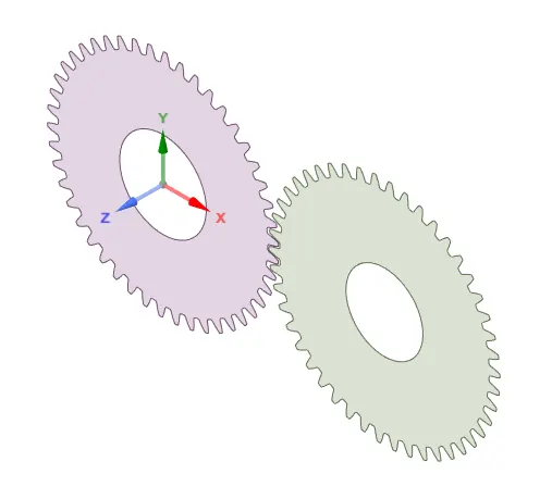
The surfaces of both gears shown in the orange color shown in the below image has been copied & pasted in the new part to created surface geaometry which will be used to perform simulation.
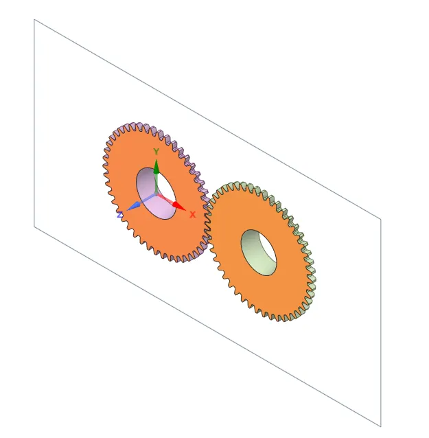
Final geometry:
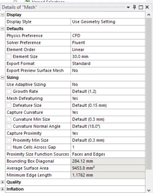
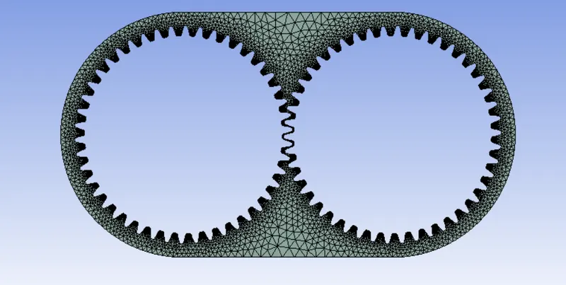
Mesh Settings:
The mesh setting has been kept shown in the below image.
Element size = 30mm
Following options has been tuned on to capture small geometry, curvature & gaps.
Capture Curvature: Yes
Capture Proximity: Yes
Mesh method has also been inserted. The "All Triangle Method" has been used to create tetra mesh.
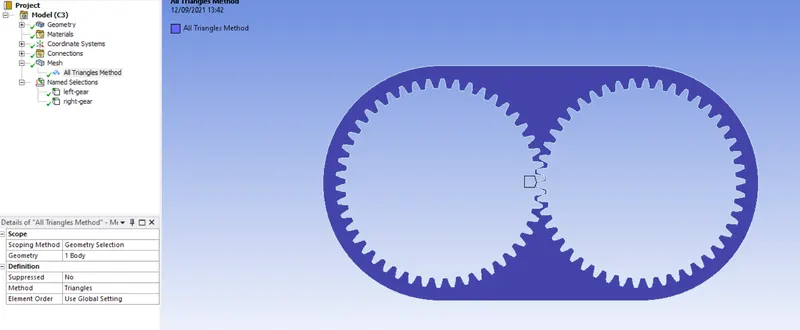
Final Mesh:
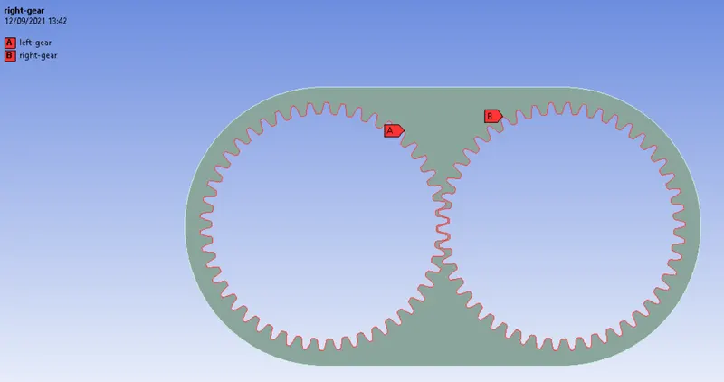
Named reference surfaces has been created for the left & right gear.
Simulation Setup:
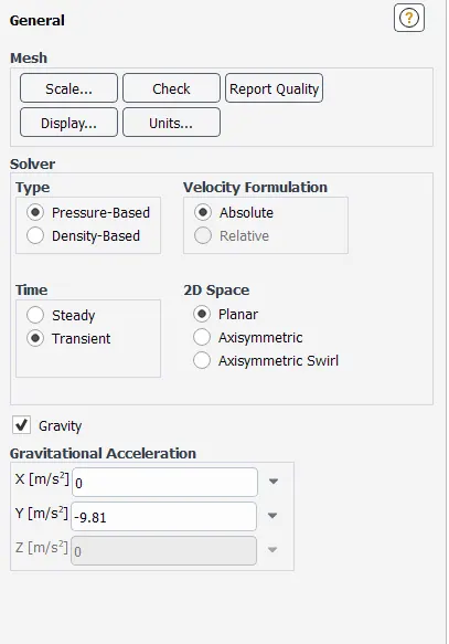
The simulation has been setup initially using following options:
Solver - Pressure Based
Time - Transient
Gravity - On (-9.81 m/s^2 in Y direction)
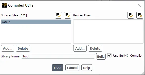
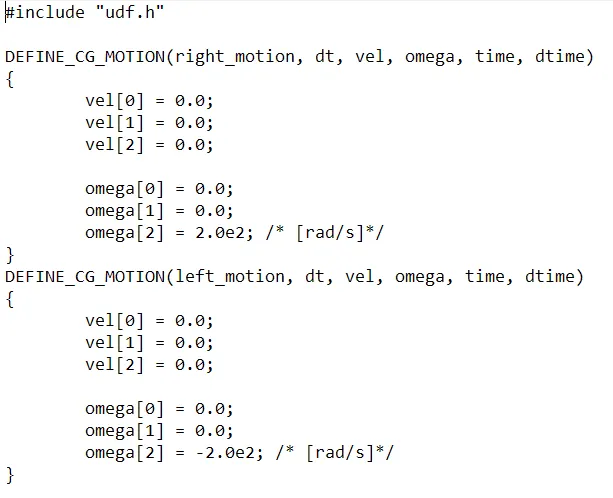
The UDF has been loaded using following option. First the already created UDF file has been called to load the function. Using in-built compiler, the function has been extracted & loaded into the system.
The given UDF is copied in the below image:
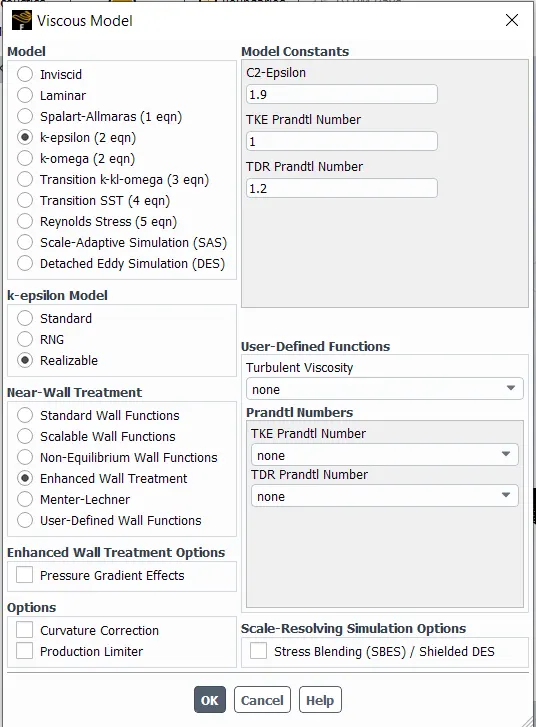
k-epsilon (2 eqn) model has been used with Realizable function & enhanced wall treatment options. As in this simulation, the importance is not to capture near wall physics, k-omega sst model was not used to simulate.
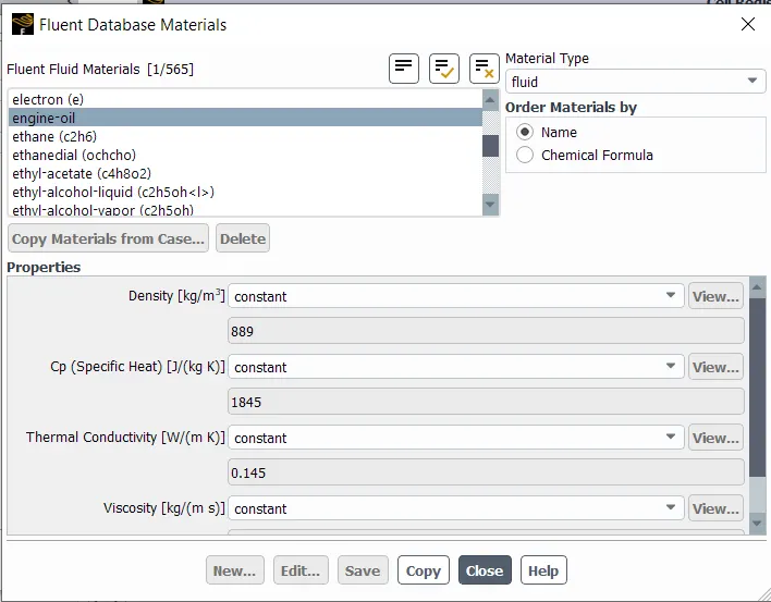
Following material combinations has been loaded into the system for 2 different simulation configurations in a similar way.
Air - Engine Oil
Air - n-heptane liquid
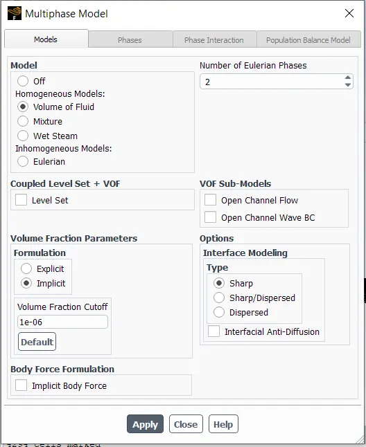
Multiphase model has been applied using "volume of fluid" option. Implicit formulation has been used for volume fraction parameters.
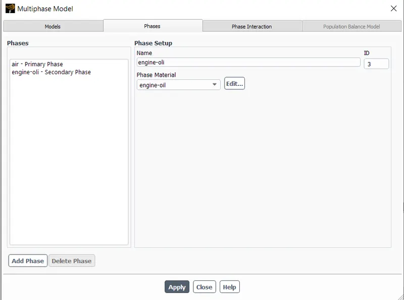
After applying multiphase model, names has been assigned to theri respective region. Following image shows for the air & engine oil simulation, but in the similar way for air - n heptane liquid has been executed.
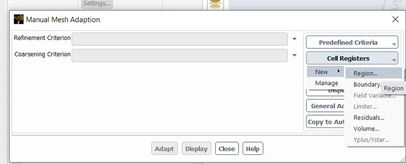
To create the seperate region for the engine oil in the gearbox housing, the mesh adaptation option has been used.
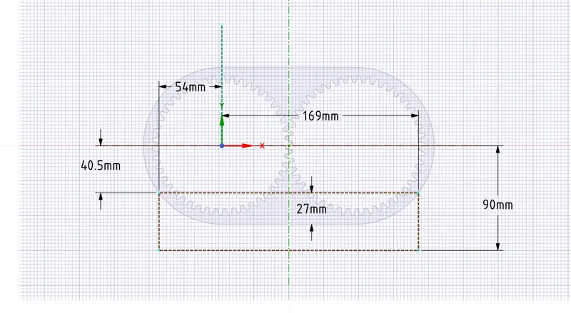
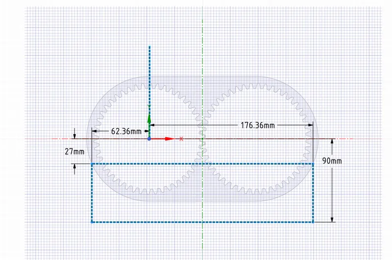
The region has been created by entering the coordinates to cover either engine oil or n-heptane liquid in the housing. Following image shows the rectangle drawn in construction line to measure the coordinate to mark the level the liquid. Following dimension is for 20% liquid lel inside housing. In similar way, the coordinates has been measured for 30% level.
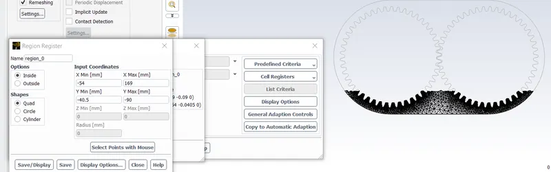
The marked region using above coordinate has been shown in below image. The black region displays the level of 20% liquid in the housing.
In following steps, dynamic mesh has been created.
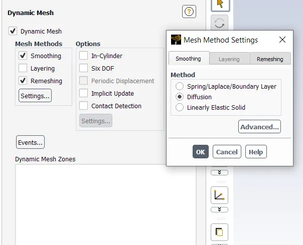
Mesh Methods: Smoothing & Remeshing options has been selected.
Smoothing: This option is used where the mesh zone's moving or deforming boundary needs to be readusted with the timesteps. Smoothing maintains the interior nodes of the mesh zone moves with the motion, but their connectivity & number of nodes inside that zone remain same. This way interior nodes "absorb" the movement of the boundary.
In smooting option, there are three more sub-option available. Out of those three options, diffusion has been selected for this simulation.
Diffusion option is very useful in creating very quality mesh & especially for the mesh whose boundaries are moving or deforming. This option allows larger boundary deformation before creaking down compare to spring-based smoothing. This option, similar to spring based smoothing, can handle translational boundary deformation much better than rotational motions.
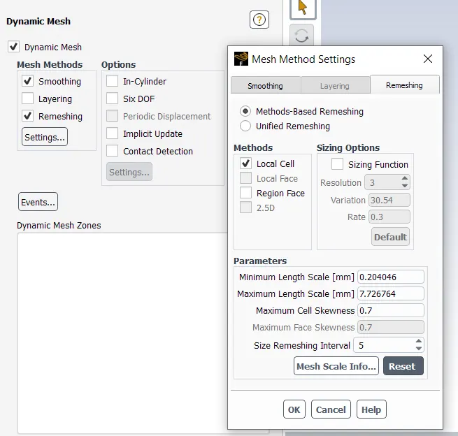
Remeshing: With only mesh smoothing option, the mesh element will deteriorate or degenerate in case of large displacement of cell compare to the size of the local elements. In this condition, the mesh will be invalidated & "negative cell volume" error will be thrown onto the screen and this condition will lead to the convergence problem when the solution is updated to the next time step.
To resolve this issue, Ansys agglomerates cells that violate the skewness or sixe criteria & locally remeshes the agglomerated cells or faces. If the new cells or faces satisfy the skewness criterion, the mesh is locally updated with the new cells & solutions will be interpolated from the old cells.
This option also has several options available depends on the mesh type(2d or 3d), element types. For this simulation, "local mesh" option has been selected. This option only affects triangular & tetrahedral cell types in the mesh, which means in the mixed cell zone, non-triangular & non-tetra elements will be skipped.
While using the local remeshing method (thatis, local cell remeshing with ot without local face remeshing), Ansys Fluent marks cells on the basis of following criteria: Cell Skewness, Minimum & maximum length scales as well as an optional sizing function.
Ansys fluent evaluates each & every elements and marks them for the remeshing if it meets one or more of the following criteria:
- Cell skewness is greater than the maximum specified skewness
- minimum length scale is smaller than the specified
- maximum length scales is larger than the specified.
- Its height does not meet the specified length scale especially at moving zones, like above a moving piston.
The criteria for maximum & minimum length scale and maximum skewness has been selected uisng default option.
In any case, if the local remeshing methods unable to reduce the cell skewness sufficiently, than the cell zone remeshing method is used to automatically remesh all of the cells in the cell zone, as well as the faces of all adjacent deforming dynamic face. Tha maximum allowable cell skewness is set to 0.9 by defualt for 3d & 0.7 for 2d elements. The cell zone remeshing method gives the mesher more flexbility to create a new mesh of better quality than the local cell remeshing method.
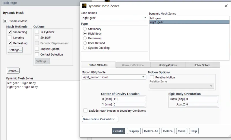
Dyncamic mesh zones has been created for the right & left gear & centre of gravity location has been added for both gears. For left, it is (0,0) & for the right, it will be (115mm, 0).
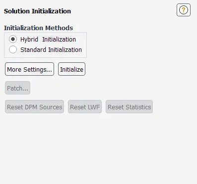
Simulation has been initialized using the hybrid method, as we dont have inlet & outlet defined in this simulation.
The patch has been generated between two phases, air & engine oil or n-heptane liquid. Volume fraction method has been used to define portion of engine oil in the region created during Mesh Adaptation step as mentioned in earlier step.
The option selected by default under "Volume Fraction Patch Options" has been deselected.
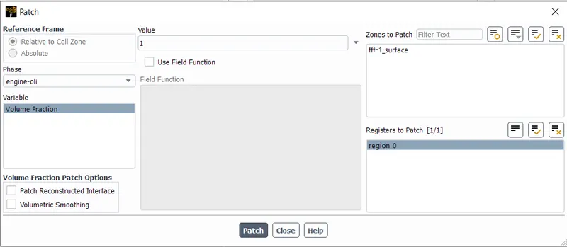
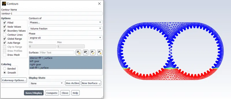
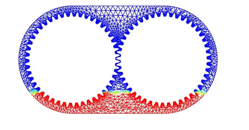
For post-processing, the contour plot has been created using the option shown in the image below. The contour plot has been plotted on the screen as shown on the right side of the image which is the initial condition inside the gear box housing before any rotation.
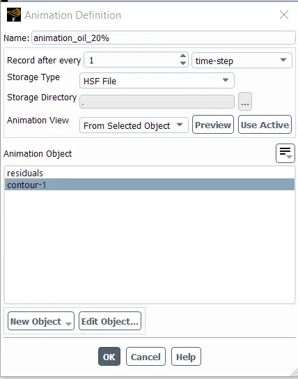
Using the contour plot generated in above step, the animation has been created in which all contour plot of each step has been saved & tha animation will be created by stitching all images of each & every time steps.
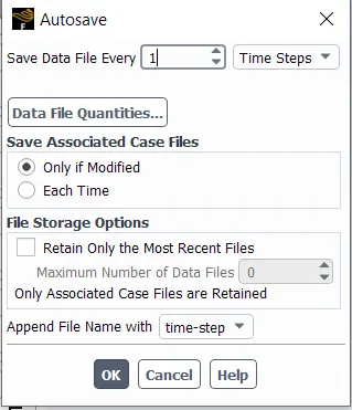
To create animation or to visualize animation in CFD-Post software, data will be saved for every timetep.
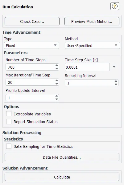
The simulation will be executed using 1e-4 timestep size & total 700 number of time steps. And maximum 20 iterations per time step.
Part 1: Simulation Results for given options
- 20% Immersion, Fluid - Engine oil.
20% engine oil immersion condition
sketch to find coordinates - applicable to both fluid - engine oil & n-heptane liquid
Contour Plot
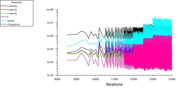
Result - Residual Plot
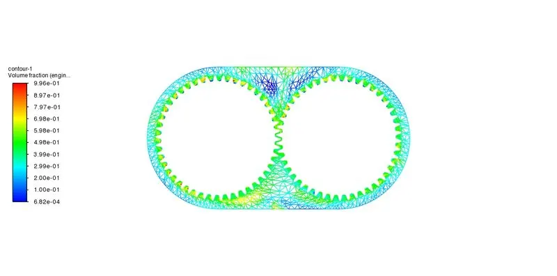
Result - Contour Plot
2. 30% Immersion, Fluid- Engine oil.
30% fluid immersion condition
sketch - applicable to both fluid
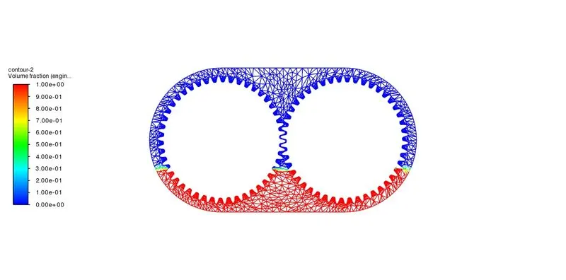
Contour Plot - Initial Condition
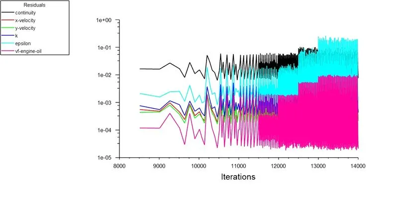
Results - Residual Plot
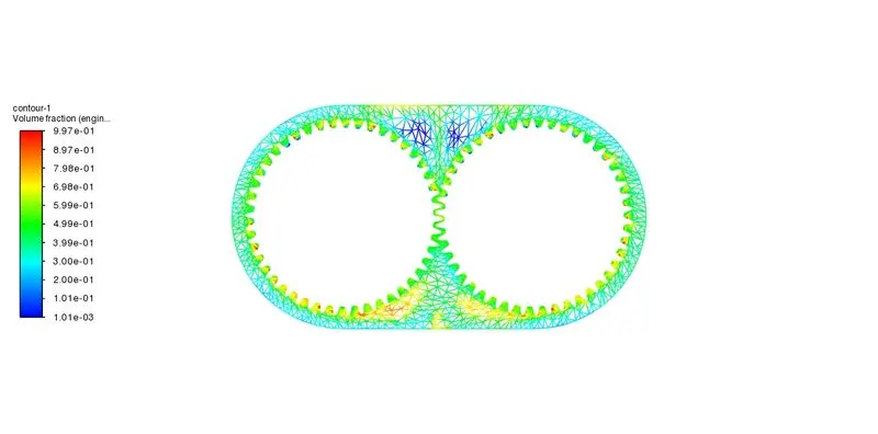
Results - Contour Plot
Animation Link:
3. 20% Immersion,Fluid-n-heptane (c7h16).
Contour Plot - Initial Condition
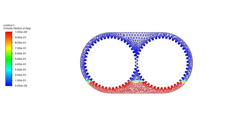
Results -
Contour Plot
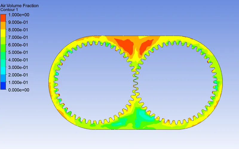
Animation Link:
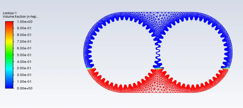
4. 30% Immersion,Fluid-n-heptane (c7h16).
Contour - Initial Condition
Results - Residual Plot
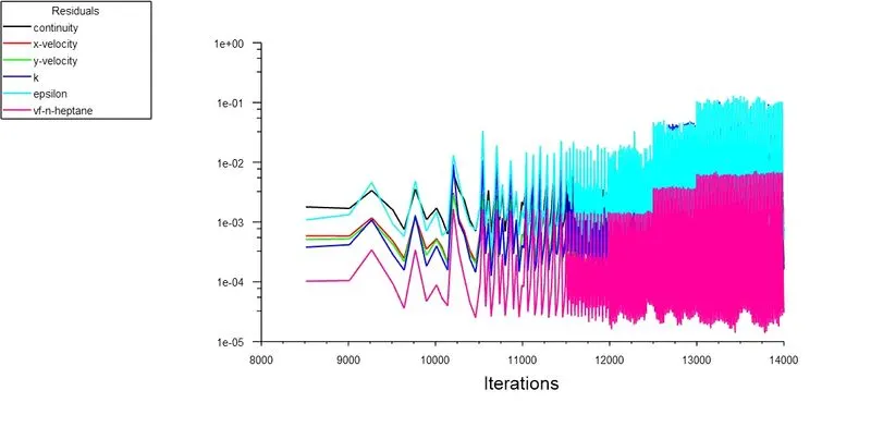
Results - Contour Plot
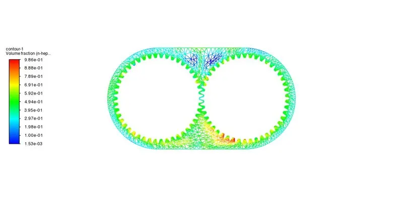
Animation Link:
Results Discussions:
- To decide the better liquid between engine oil & n-heptane liquid, it is important to observe the distribution of each fuel around the teeths & if it is uniformly distributed in all teeths than that liquid will be very suitable for the lubrication purpose.
- In the volume fraction plots, the blue color shows the respective liquid of that simulation. In engine oil case, the blue color is much more uniform compare to n-heptane liquid. And in 30% immersion condition of engine oil, the blue color is even more uniformly distributed. In case of n-heptane liquid, blue color is missing from many teeths.
Part 2:
- What is Dynamic meshing? Give some other examples where dynamic meshing can be used.
- Dynamic meshing allows to move the boundary of the mesh elements realtive to the other boundaries of the zone & adjust the mesh & elements accordingly which is very useful in certain applications. The applications where mesh is deforming or the mesh deformation is the function of solution as in case of six degrees of freedom solver. In dynamic mesh, boundaries of the mesh can move rigidly (in case of linear or rotational) with respect to other or can deform.
- Rigid boundary mesh applications - piston moving inside the engine cylinder, aircraft wing flap movement
- Deforming boundary application - elastic wall of balloon while inflating, flexible artery wall responding to the pressure pulse from the heart.
- Other application of dynamic mesh - rotation of gears inside gear casing, water wheel & dropping a ball into a water container case.
2. What is the fluid Sloshing effect? Discuss whether the sloshing effect is good or bad? Explain.
- In fluid dynamics, the sloshing means the movement of the liquid inside another object especially when another object is under motion.
- It is the motion of the free surface liquid inside the partially filled vessel or any other object which is experienced in mariane, automotive, rail or aerospace industries. During slosing effect, the liquid exert dynamic force on the object which may cause leakage or might damage the object or its supportive structure.
- The sloshing motion is highly nonlinear and random process depending on the motion of the object, liquid depth, liquid properties and the geometry of the object.
3. What is the use of UDF?
- UDF means User Defined Function.
- It allows the users to create their own functions which can be routine tasks or procedures that computer can follow. It can be the process made of series of task or specifin function that user simply call it every time it is needed.
- Basically, UDF is the basic building blocks written in C programming language in the modular structure. It is can be used addition to the standard features of the Ansys fluent to enhance their capability. It can have information like boundary conditions, material properties, source terms of flow regime or code to initialize a solution.
4. Discuss the common errors that occurred in the simulation. A] 'Dynamic mesh failed' error. B] 'Negative cell volume detected' error.
A] Dynamic mesh failed error - Reasons are as follows:
- Bad quality mesh - for both structured & unstructured mesh, it may result in comoutation errors thus causing the simulation residuals to crash.
- Settings of the dynamic mesh is not as per the geometry or simulation requirements. For example, current simulation is using 2D geometry, thats why "Layering" option kept disabled because it is used for 3D geometry.
- Geometry is not properly selected or assigned for the boundary condition.
B] Negative Cell Volume Error
- When the distance moved by a cell in one time step is greater than the cell size in the dynamic mesh region, the ansys will throw this error. The error can be resolved by properly selecting timestep size & number of time steps to perform simulation and also suitable options in the dynamic mesh dialogue box.